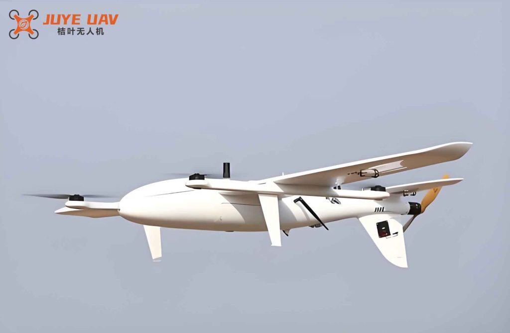
In our work on transmission line maintenance, fixed-wing drones have become essential tools for long-range inspection tasks. As the payload and flight distance increase, the size and weight of these fixed-wing drones grow considerably. For example, models such as the CW-30 require pre-flight calibration of the inertial measurement unit (IMU) and magnetic compass, which involves pitching and rolling the drone by ±10° and rotating it 360°. Performing these maneuvers manually with multiple personnel poses risks of drone falls and injuries. To address this, we designed a pre-flight inspection platform specifically for fixed-wing drones used in power transmission lines.
Our platform integrates a Hooke joint driven by electric push rods to achieve bidirectional tilting, and a slewing bearing mechanism to realize full rotation. In this paper, we present the design process, verification, and field application of the platform, demonstrating its smooth operation and accurate calibration for fixed-wing drones.
1. Introduction
Unmanned aerial vehicles (UAVs) have been widely adopted in transmission line construction and maintenance. Initially used for pulling lightweight pilot lines, fixed-wing drones now carry multi-spectral cameras, LiDAR, and infrared sensors for comprehensive inspection tasks. However, the increased size and weight of these drones introduce challenges in pre-flight calibration. For a typical fixed-wing drone like the CW-30, the IMU calibration requires tilting the drone forward/backward (pitch) and left/right (roll) by at least 10°, while the magnetic compass calibration necessitates a full 360° yaw rotation. Manual performance of these steps by several workers is inefficient and dangerous. Therefore, we aimed to develop an automated platform that can carry out these calibrations safely and accurately for fixed-wing drones.
2. Requirements Analysis
We conducted field surveys to define the functional and technical parameters of the pre-flight inspection platform. The key requirements are summarized in Table 1.
| Parameter | Specification |
|---|---|
| Compatible fixed-wing drone models | CW-30, CW-20 (representative types) |
| Maximum payload capacity | ≥ 34 kg |
| Pitch angle range (forward/backward) | ≥ ±10° |
| Roll angle range (left/right) | ≥ ±10° |
| Yaw rotation | Full 360° continuous |
The calibration procedure using the platform is illustrated in Figure 1 (conceptual flowchart). The drone is first placed on the platform and secured. Then the platform sequentially performs pitch, roll, and yaw motions while the onboard calibration software completes the sensor adjustments. Finally, the platform returns to the horizontal position and the drone is ready for flight.
3. Overall Design
The platform consists of four main modules: a rotation platform module, a bidirectional tilt module, a support module, and an electrical control module.
3.1 Rotation Platform Module
This module holds the fixed-wing drone and provides 360° rotation for magnetic compass calibration. We performed a static analysis of a typical fixed-wing drone by simplifying its structure into four main components: fuselage, wings, booms, and tail. The center of gravity was determined to be at the projection point near the intersection of the fuselage and the leading edge of the wing. The rotation axis of the platform must align with this projection point to ensure stability.
To secure the drone without damaging its thin composite shell, we used elastic cushioning pads at the main contact points. Additional clamping points were placed on the drone booms (60 mm diameter carbon fiber tubes) using stainless steel ring clamps, which provide high strength and distribute stress. The rotation is achieved by a slewing bearing with IP67 sealing, allowing operation in dusty or rainy field conditions. The bearing is flange-mounted to reduce overall height and mass.
3.2 Bidirectional Tilt Module
This module is mounted below the rotation platform and provides ±10° pitch and roll motions for IMU calibration. We selected a Hooke joint structure decoupled into two independent axes (Axis A for pitch, Axis B for roll) to achieve high precision and load capacity. The two axes are driven independently by electric push rods. The push rods are connected via U-shaped brackets. Figure 2 shows the arrangement.
We performed motion simulation for eight extreme tilt cases (Table 2) using UG software. The minimum clearance between moving parts was 2.3 mm (for Cases 5 and 6), satisfying safety requirements.
| Case | Axis A (°) | Axis B (°) | Critical clearance location |
|---|---|---|---|
| 1 | +10 | 0 | Axis A gap |
| 2 | -10 | 0 | Axis A gap |
| 3 | 0 | +10 | Axis B gap |
| 4 | 0 | -10 | Axis B gap |
| 5 | +10 | +10 | U-shaped bracket clearance |
| 6 | -10 | -10 | U-shaped bracket clearance |
| 7 | +10 | -10 | U-shaped bracket clearance |
| 8 | -10 | +10 | U-shaped bracket clearance |
We verified the strength of the long shafts (made of LD30 aluminum alloy, 40×40 mm profile) under a concentrated load of 0.6 kN. The maximum bending moment is calculated as:
$$ M = \frac{F \times L}{2} = 11760 \ \text{N·mm} $$
The section modulus is:
$$ W = \frac{I}{r} = 2600 \ \text{mm}^3 $$
Thus the maximum bending stress is:
$$ \sigma = \frac{M}{W} = 4.52 \ \text{MPa} $$
With a safety factor of 3, this is well below the allowable stress of 58.3 MPa. The U-shaped brackets were analyzed using finite element method (FEM) under a 588 N load. The maximum von Mises stress was 45 MPa, below the 68.3 MPa allowable stress for 304 stainless steel.
3.3 Support Module
The support module consists of a vertical column and a cross-shaped base. The column is made of 40×40 mm aluminum profile (LD30) and connects to the Hooke joint’s Axis A. It is designed for pure axial compression because the Hooke joint isolates torque. We performed buckling analysis using Euler’s formula.
The slenderness ratio is:
$$ \lambda_1 = \sqrt{\frac{\pi^2 E}{\sigma_p}} = \sqrt{\frac{\pi^2 \times 60 \times 10^3}{175}} = 58 $$
The radius of gyration:
$$ i = \sqrt{\frac{I}{A}} = \sqrt{\frac{52000}{332}} = 12.2 \ \text{mm} $$
The effective slenderness ratio (with effective length factor μ=2 for fixed-free end condition):
$$ \lambda = \frac{\mu l}{i} = \frac{2 \times 400}{12.2} = 65 > \lambda_1 $$
Thus Euler’s formula applies:
$$ \sigma_{cr} = \frac{\pi^2 E}{\lambda^2} = \frac{\pi^2 \times 60}{65^2} = 140 \ \text{MPa} $$
The actual compressive stress under 60 kg load is:
$$ \sigma = \frac{F}{A} = \frac{60 \times 9.8}{332} = 1.77 \ \text{MPa} $$
This is far below the critical stress, so the column is safe.
3.4 Electrical Control Module
To ensure safety during operation, we used a remote control system based on 433 MHz wireless communication. The operator sends commands via a handheld transmitter to two relays that drive the electric push rods. This low-power, high-penetration signal is suitable for outdoor fieldwork. The control module only manages the tilt motions; the rotation platform is rotated manually or integrated with a separate motor in future designs. For the current prototype, the rotation is performed by the operator turning a hand crank or using a simple motorized slewing drive with a separate controller.
4. Platform Application
After fabrication, we conducted tests following the standard DL/T875-2016. We verified all extreme tilt positions; no interference occurred. The repeatability of tilt angles was within ±0.5° after three consecutive cycles. Then we performed a load test with a CW-30 fixed-wing drone (mass 17±0.2 kg) secured on the platform. The platform executed ±10° pitch and roll motions and a full 360° rotation. All motions were smooth, and the drone remained securely fixed. The onboard IMU and compass calibration were successfully completed.
We applied the platform in a real 750 kV transmission line inspection mission. The platform was used for pre-flight checks of the fixed-wing drone. Table 3 summarizes the key performance metrics observed during field use.
| Metric | Value |
|---|---|
| Platform setup time | < 5 min |
| Tilt angle accuracy (pitch & roll) | ±0.5° |
| Rotation accuracy (yaw) | ±0.5° |
| Number of calibration cycles performed | 3 per flight mission |
| Time saved per calibration | ~10 min (vs. 3-person manual handling) |
| Operator safety incidents | 0 |
The platform significantly improved pre-flight efficiency and eliminated the risk of drone falls during manual tilting. The field personnel reported that the platform was easy to operate and required only one person for the entire calibration process.
5. Conclusion
We have designed and implemented a pre-flight inspection platform specifically for fixed-wing drones used in transmission line maintenance. The platform uses a decoupled Hooke joint with electric push rods to achieve ±10° pitch and roll, and a slewing bearing for 360° yaw rotation. All components were verified through simulation and load testing. Field application on a 750 kV transmission line demonstrated that the platform operates smoothly, meets the calibration requirements for IMU and compass, and significantly improves safety and efficiency compared to manual handling. Future work will include adding angle sensors and integrating them into a fully automated calibration sequence for the fixed-wing drone.