In recent years, the fixed-wing drone has been increasingly applied across various industries due to its low cost, high flexibility, low risk, and operational convenience. This technology is experiencing rapid development and becoming more mature. The fixed-wing drone is extensively used in surveying, carrying cameras and other mapping equipment. For instance, an electric fixed-wing drone with a flight endurance of 2.5 hours and a cruising speed of 80 km/h can cover an area of 20 km² per flight. This advantage is particularly significant in emergency rescue after natural disasters such as earthquakes and floods. The aerodynamic efficiency of fixed-wing drones is exceptional, providing long endurance and a large operational range, making them especially outstanding in large-scale monitoring, particularly in forest fire prevention. Moreover, the fixed-wing drone is an ideal tool for long-distance inspections of transmission lines and oil pipelines in remote areas.
The UV20 drone system is a fully autonomous unmanned aerial vehicle system based on GPS navigation. Its electric flight endurance is 1 hour and 30 minutes. The system carries a payload (Canon 5D III digital camera) to perform remote sensing flight missions, acquiring remote sensing data fully automatically and with high precision. The launch and recovery methods are catapult-assisted takeoff and parachute recovery, with automatic execution of the catapult and parachute deployment processes according to the program.
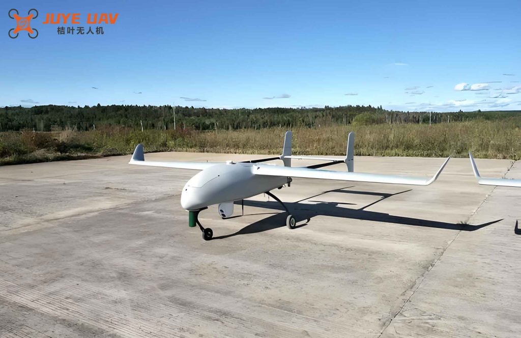
System Composition of the UV20 Fixed-Wing Drone
The UV20 fixed-wing drone system consists mainly of the airframe, flight control system, data link system, ground station system, payload system, and catapult launch system. The airframe includes the fuselage, wings, tail, propulsion device, flight control surfaces, and power supply system. The flight control system, also known as the autopilot, is the most critical component, responsible for navigation and control, handling autonomous takeoff, climb, cruise, descent, and recovery. The UV20 uses a Micropilot MP2028 autopilot, which integrates all functions of an unmanned aerial vehicle autopilot. The data link system uses a radio transmitter to communicate with the aircraft via an antenna, enabling data transmission for control and status monitoring. The ground station system, using ground control software and a data communication system, performs flight route planning, status detection, key data monitoring, real-time flight data (position, speed, altitude, etc.), route monitoring and modification, and payload control. The ground station interface has three main functional areas: map display, control, and real-time telemetry. The payload system comprises various mission equipment such as cameras and radar. The UV20 carries a Canon 5D Mark III digital camera with a 35 mm fixed-focal-length lens. The catapult launcher consists of a rail, rubber rope, winch with a trolley, and a tension meter. The rail is foldable in three sections, each 1 m long, for a total length of 3 m. The winch, driven by a 12 V battery, pulls the trolley to increase tension.
The following table summarizes the key components and their functions:
| Component | Function |
|---|---|
| Airframe | Provides structure, propulsion, and power distribution |
| Flight Control System (Autopilot) | Navigation, attitude control, autonomous mission execution |
| Data Link System | Radio communication for telemetry and command |
| Ground Station System | Mission planning, real-time monitoring, payload control |
| Payload System | Image acquisition (Canon 5D III with 35mm lens) |
| Catapult Launcher | Provide initial acceleration for takeoff |
Minimum Operational Conditions for the UV20 Fixed-Wing Drone
Through extensive testing, the minimum conditions for safe operation of the fixed-wing drone have been determined. These include requirements for the takeoff and landing area, weather, and other environmental factors.
Takeoff and Landing Site Requirements
The UV20 fixed-wing drone relies on a catapult for takeoff and a parachute for landing. During takeoff, there is a low-altitude glide phase, and during landing, the parachute opens and the drone descends gently. Therefore, the surrounding environment must be carefully considered. Based on numerous flights, the site requirements are as follows: the terrain must be flat; in the takeoff direction, there should be no obstacles (such as flagpoles, utility poles, or trees) within 1000 m in the forward direction and 500 m laterally. Wind speed and direction are crucial. The takeoff and landing site should be on the windward side of a slope, avoiding valleys or leeward sides where turbulence can occur. The wind must be stable. During descent, the wind at ground level may differ from higher altitudes, complicating the accurate prediction of the parachute opening point. Additionally, the ground station radio link must have a clear line of sight between the antenna and the aircraft; no large buildings or mountains should obstruct the signal. The radio range is approximately 30 km, so the distance between the takeoff site and the mission area should not exceed 30 km.
Weather Conditions
Thunderstorms and rainy weather are prohibited because the electronic components are not waterproof. The maximum allowable wind speed is 8 m/s; beyond this, the aircraft’s airspeed during downwind flight may drop below the safe threshold, causing loss of attitude control. The following table summarizes the key operational limits:
| Parameter | Requirement |
|---|---|
| Takeoff direction obstacle clearance | 1000 m forward, 500 m lateral |
| Terrain | Flat, preferably windward slope |
| Wind speed | ≤ 8 m/s |
| Precipitation | No rain or thunderstorms |
| Radio link range | ≤ 30 km from ground station to mission area |
| Line of sight | No obstructions between ground station antenna and aircraft |
Image Acquisition and Processing Workflow
The workflow for the fixed-wing drone aerial imaging system is divided into three phases: pre-flight preparation, in-flight execution, and post-flight data processing and quality control.
Pre-Flight Preparation
First, charge the onboard power battery. Set the charger current to 2–3 A for normal charging; in urgent cases, a fast charge at 5 A may be used, though frequent fast charging is discouraged for battery longevity. Check the ground station portable computer for reliability—avoid any that freeze, blue-screen, or exhibit slow response. Ensure sufficient battery charge. Charge the catapult launcher winch battery. Inspect the catapult rail for deformation, rubber ropes for damage, and the release mechanism for proper operation. Pre-download map tiles in the ground station software for the mission area (cache up to level 15) and pre-plan the flight route. Select 2–3 candidate takeoff/landing sites within 30 km of the mission area.
The ground sampling distance (GSD) is a critical parameter for aerial imaging. For the UV20 fixed-wing drone equipped with a Canon 5D III camera (pixel size 6.4 µm) and a 35 mm lens, the GSD at a given flight altitude \( H \) is given by:
$$
\text{GSD} = \frac{p \cdot H}{f}
$$
where \( p \) is the pixel size (6.4 × 10⁻⁶ m) and \( f \) is the focal length (0.035 m). For example, to achieve a GSD of 15 cm, the required flight height is:
$$
H = \frac{\text{GSD} \cdot f}{p} = \frac{0.15 \times 0.035}{6.4 \times 10^{-6}} \approx 820 \, \text{m}
$$
However, due to terrain and obstacle constraints, the actual flight height used in the test was 1200 m, giving a GSD of approximately 22 cm. The side overlap and forward overlap are set to 50% and 80% respectively. The distance between adjacent flight lines \( D_{\text{line}} \) can be calculated as:
$$
D_{\text{line}} = (1 – \text{side overlap}) \times \text{swath width}
$$
where the swath width is the image footprint width: \( \text{swath width} = \frac{\text{sensor width} \cdot H}{f} \). For the full-frame Canon 5D III, sensor width is 36 mm, so at H = 1200 m:
$$
\text{swath width} = \frac{0.036 \times 1200}{0.035} \approx 1234 \, \text{m}
$$
$$
D_{\text{line}} = (1 – 0.5) \times 1234 = 617 \, \text{m}
$$
In-Flight Execution
Select the takeoff point at the downwind side of the field, with the launch direction facing the wind (northeast in our test). Assemble the catapult launcher, level it, and ensure an appropriate launch angle. Test the catapult with a dummy mass: pull the trolley back to a tension of 210 N, release, and measure the travel distance. A distance exceeding 20 m indicates proper function. Then assemble the aircraft: install wings, tail, power battery, recovery system (parachute and airbags), and payload (camera). Set up the ground station antenna and connect the radio. After establishing a communication link, check the telemetry data: verify the battery voltage is above 25 V, test the motor to ensure RPM exceeds 6900 r/s, test the parachute deployment mechanism, and perform a test camera shot. Once all checks pass, upload the flight plan to the autopilot. The UV20 fixed-wing drone is launched via catapult. It climbs autonomously to an altitude of 300 m and holds a loiter pattern. The ground station operator confirms normal operation and then commands the drone to start the imaging mission. The drone flies to the first waypoint, acquires images line by line, and after completing all lines, automatically returns to the launch site, loitering at 300 m overhead. For landing, the operator considers wind conditions to determine the parachute opening point. Upon activation, the parachute deploys, and ground crew quickly retrieves the drone to prevent dragging.
The following table provides the detailed mission parameters for a test area of approximately 60 km²:
| Flight Sortie | Coverage (km²) | Number of Lines | Total Line Length (km) | Flight Direction (deg) |
|---|---|---|---|---|
| 1 | 8 | 8 | 114 | 340 |
| 2 | 16 | 8 | 59 | 340 |
| 3 | 19 | 8 | 58 | 340 |
| 4 | 18 | 9 | 60 | 340 |
These four sorties together cover the full area. The total number of images acquired was 1226, each with corresponding POS data.
Post-Flight Data Processing and Quality Control
After landing, download the image data and POS (position and orientation system) data. Check that the number of images matches the number of POS records (1226 each). Use GIS software to plot the image center points from POS coordinates to verify coverage. Visually inspect each image for clarity, lack of smudges, clouds, or other defects. All images in this test were sharp and usable.
The photogrammetric processing is performed using software (e.g., PhotoScan). The workflow involves three main steps: data preparation, computation, and output. First, import the images and POS data into the software. In the geographic reference tab, match the images with their POS coordinates. Next, perform an initial alignment (image relative orientation) with processing accuracy set to medium or high. Then optimize the alignment by solving the collinearity equations (bundle adjustment) to achieve an unconstrained aerial triangulation. After that, measure ground control points (GCPs) on the images. Import the GCP coordinates and manually identify the points on each image. Run a second optimization with the GCP constraints to obtain a constrained aerial triangulation. Check the control point residuals and eliminate gross errors. The typical residual tolerance is within 1–2 pixels. Then generate a dense point cloud, build a mesh (DSM), and finally create the orthomosaic (DOM). Export the DOM in TIFF format with a specified ground resolution, along with TFW and pyramid files. Optionally generate a project report including camera calibration data, control point accuracy, and processing parameters.
The orthomosaic generation accuracy can be evaluated using the root mean square error (RMSE) of the check points:
$$
\text{RMSE} = \sqrt{\frac{1}{n} \sum_{i=1}^{n} \left( (X_i – X_i^{\text{ref}})^2 + (Y_i – Y_i^{\text{ref}})^2 \right) }
$$
In the test, the RMSE was within the required tolerance for 15 cm GSD projects (typically less than 0.3 m). The final deliverables are organized into directories: raw data (POS, images), imagery (TIFF format), and report.
Conclusion and Outlook
Based on the detailed analysis and operational experience with the fixed-wing drone system, the following flight conditions are recommended: the fixed-wing drone is the preferred choice when the total route length exceeds 200 km, a suitable takeoff/landing site exists within 30 km, and weather conditions are favorable. When wind speed exceeds 4 on the Beaufort scale (above 8 m/s), the fixed-wing drone is often the only viable option due to its superior stability. For large survey areas exceeding 60 km², especially when the required ground resolution is around 15 cm or coarser, the fixed-wing drone offers clear advantages in efficiency and endurance.
The fixed-wing drone continues to gain attention in the expanding field of unmanned aerial systems. Optimizing operational procedures is essential to maximize its performance. The workflow described here is universal and practical, providing a reliable reference for similar aerial imaging projects. Future improvements may include real-time quality assessment, automated obstacle detection during launch, and integration of advanced sensors for multispectral and LiDAR data acquisition. The fixed-wing drone remains a cornerstone technology for large-scale mapping and environmental monitoring.