
The mesmerizing spectacle of a synchronized formation drone light show represents a pinnacle of multi-agent robotics, where hundreds or thousands of unmanned aerial vehicles (UAVs) move as a cohesive, illuminated entity. The core technological challenge lies in ensuring precise geometric formation control while maintaining robust, low-latency communication among all agents in the fleet. In this article, we present a comprehensive framework addressing these challenges. We begin by establishing a rigorous mathematical model for quadrotor dynamics. Subsequently, we introduce a versatile formation constraint methodology based on linear and circular patterns. To solve the critical issue of packet collision in dense, real-time networks, we propose an enhanced Time-Indexed Circular Ad-Hoc (TIC_Ad_Hoc) communication protocol. The integration of these components provides a reliable foundation for executing complex, high-integrity formation drone light show performances.
The execution of a flawless formation drone light show is not merely an artistic endeavor but a demanding exercise in distributed control theory and wireless networking. Each drone must know its exact position relative to a global plan and its neighbors, adjusting its motors hundreds of times per second. Simultaneously, it must send and receive state data (position, velocity, battery level) and potentially receive real-time trajectory updates without causing network congestion. Traditional centralized control via a single ground station is infeasible due to latency and single-point-of-failure risks. Therefore, a decentralized or hybrid approach using a mobile ad-hoc network (MANET) is essential. However, standard MANET protocols suffer from instability due to rapid topology changes and, critically, packet collisions when many nodes attempt to broadcast simultaneously—a common scenario during dynamic formation transitions in a formation drone light show. Our work focuses on mitigating these specific issues through formalized control and a scheduled communication medium access control (MAC) layer.
Mathematical Modeling of a Quadrotor for Formation Control
Accurate control of any formation drone light show starts with a precise dynamic model of a single agent. We model each quadrotor as a rigid body with six degrees of freedom (6-DOF): translational motion in three-dimensional space and rotational motion about its three principal axes. The following assumptions simplify the model while retaining fidelity for control design: 1) The structure is symmetric and rigid, 2) The center of mass coincides with the geometric center of the body, and 3) Propeller thrust and drag are proportional to the square of motor speed.
We define two coordinate systems:
Inertial Frame (Earth-Fixed Frame), \( \mathcal{F}_I \): Denoted by orthonormal basis \( \{\vec{x}_I, \vec{y}_I, \vec{z}_I\} \), with \( \vec{z}_I \) pointing upwards against gravity.
Body Frame, \( \mathcal{F}_B \): Attached to the UAV’s center of mass, denoted by orthonormal basis \( \{\vec{x}_B, \vec{y}_B, \vec{z}_B\} \), with \( \vec{x}_B \) pointing forward, \( \vec{y}_B \) left, and \( \vec{z}_B \) upward relative to the drone.
The orientation of the body frame relative to the inertial frame is described by the Z-Y-X (or \( \psi\)-\( \theta\)-\( \phi\)) Euler angles: yaw (\( \psi \)), pitch (\( \theta \)), and roll (\( \phi \)). The rotation matrix \( \mathbf{R} \in SO(3) \) transforming a vector from \( \mathcal{F}_B \) to \( \mathcal{F}_I \) is:
$$
\mathbf{R} = \mathbf{R}_z(\psi) \, \mathbf{R}_y(\theta) \, \mathbf{R}_x(\phi)
$$
Explicitly:
$$
\mathbf{R} = \begin{bmatrix}
c_\psi c_\theta & c_\psi s_\theta s_\phi – s_\psi c_\phi & c_\psi s_\theta c_\phi + s_\psi s_\phi \\
s_\psi c_\theta & s_\psi s_\theta s_\phi + c_\psi c_\phi & s_\psi s_\theta c_\phi – c_\psi s_\phi \\
-s_\theta & c_\theta s_\phi & c_\theta c_\phi
\end{bmatrix}
$$
where \( c_\cdot = \cos(\cdot) \) and \( s_\cdot = \sin(\cdot) \).
The translational dynamics are derived from Newton’s second law. The total thrust \( T \) generated by the four rotors acts along the body’s \( \vec{z}_B \) axis. In the inertial frame, this is \( \mathbf{R} \cdot [0, 0, T]^T \). The equation of motion for the center of mass is:
$$
m \ddot{\mathbf{p}} = \begin{bmatrix} 0 \\ 0 \\ -mg \end{bmatrix} + \mathbf{R} \begin{bmatrix} 0 \\ 0 \\ T \end{bmatrix} – \mathbf{K}_d \dot{\mathbf{p}}
$$
where \( \mathbf{p} = [x, y, z]^T \) is the inertial position, \( m \) is mass, \( g \) is gravity, and \( \mathbf{K}_d \) is a diagonal matrix of linear drag coefficients. Expanding the thrust component gives:
$$
\begin{aligned}
m \ddot{x} &= T(\cos\psi \sin\theta \cos\phi + \sin\psi \sin\phi) – k_{d,x} \dot{x} \\
m \ddot{y} &= T(\sin\psi \sin\theta \cos\phi – \cos\psi \sin\phi) – k_{d,y} \dot{y} \\
m \ddot{z} &= T(\cos\theta \cos\phi) – mg – k_{d,z} \dot{z}
\end{aligned}
$$
The rotational dynamics are derived from the Euler equation for rigid body rotation:
$$
\mathbf{J} \dot{\boldsymbol{\omega}} + \boldsymbol{\omega} \times \mathbf{J} \boldsymbol{\omega} = \boldsymbol{\tau} – \mathbf{K}_r \boldsymbol{\omega}
$$
Here, \( \boldsymbol{\omega} = [p, q, r]^T \) is the angular velocity in \( \mathcal{F}_B \), \( \mathbf{J} \) is the inertia matrix, \( \boldsymbol{\tau} = [\tau_\phi, \tau_\theta, \tau_\psi]^T \) is the control torque vector, and \( \mathbf{K}_r \) is a diagonal matrix of rotational drag coefficients. The relationship between Euler angle rates \( [\dot{\phi}, \dot{\theta}, \dot{\psi}]^T \) and \( \boldsymbol{\omega} \) is given by:
$$
\begin{bmatrix} p \\ q \\ r \end{bmatrix} =
\begin{bmatrix}
1 & 0 & -s_\theta \\
0 & c_\phi & c_\theta s_\phi \\
0 & -s_\phi & c_\theta c_\phi
\end{bmatrix}
\begin{bmatrix} \dot{\phi} \\ \dot{\theta} \\ \dot{\psi} \end{bmatrix}
$$
The control inputs for a standard quadrotor are the squared angular speeds of the four rotors, \( \Omega_i^2 \). The mapping from rotor speeds to total thrust \( T \) and body torques \( \boldsymbol{\tau} \) is linear:
$$
\begin{bmatrix} T \\ \tau_\phi \\ \tau_\theta \\ \tau_\psi \end{bmatrix} =
\begin{bmatrix}
k_f & k_f & k_f & k_f \\
0 & -k_f l & 0 & k_f l \\
-k_f l & 0 & k_f l & 0 \\
k_m & -k_m & k_m & -k_m
\end{bmatrix}
\begin{bmatrix} \Omega_1^2 \\ \Omega_2^2 \\ \Omega_3^2 \\ \Omega_4^2 \end{bmatrix}
$$
where \( k_f \) is the thrust coefficient, \( k_m \) is the moment coefficient, and \( l \) is the arm length from the center to a motor. For control design, we typically define virtual control inputs \( U_1, U_2, U_3, U_4 \):
$$
\begin{aligned}
U_1 &= k_f (\Omega_1^2 + \Omega_2^2 + \Omega_3^2 + \Omega_4^2) \quad &\text{(Total Thrust)} \\
U_2 &= k_f l (-\Omega_2^2 + \Omega_4^2) \quad &\text{(Roll Torque)} \\
U_3 &= k_f l (-\Omega_1^2 + \Omega_3^2) \quad &\text{(Pitch Torque)} \\
U_4 &= k_m (\Omega_1^2 – \Omega_2^2 + \Omega_3^2 – \Omega_4^2) \quad &\text{(Yaw Torque)}
\end{aligned}
$$
This model forms the basis for designing attitude and position controllers for each agent in the formation drone light show.
| Symbol | Description | Typical Unit |
|---|---|---|
| \( \mathbf{p}, \dot{\mathbf{p}}, \ddot{\mathbf{p}} \) | Position, Velocity, Acceleration in \( \mathcal{F}_I \) | m, m/s, m/s² |
| \( \phi, \theta, \psi \) | Roll, Pitch, Yaw Euler Angles | rad |
| \( \boldsymbol{\omega} \) | Angular Velocity in \( \mathcal{F}_B \) | rad/s |
| \( m, \mathbf{J} \) | Mass and Inertia Tensor | kg, kg·m² |
| \( k_f, k_m \) | Thrust and Moment Coefficients | N·s², N·m·s² |
| \( l \) | Arm Length (Center to Motor) | m |
| \( U_1, U_2, U_3, U_4 \) | Virtual Control Inputs | N, N·m, N·m, N·m |
| \( \Omega_i \) | Angular Speed of i-th Rotor | rad/s |
Formation Geometry Definition via Linear-Circular Constraints
For a formation drone light show, the desired pattern must be mathematically defined in a way that is scalable, easy to compute for each drone, and allows for smooth transitions. We propose a parametric method that combines lines and concentric circles (or “hyper-circles”/ellipses). This approach is particularly effective for defining common show elements like grids, lines, curves, and logos.
The core idea is to define a formation template in a 2D plane (often the horizontal plane, which can later be extruded to 3D). A virtual leader or formation centroid at \( (x_0, y_0) \) serves as the reference. The desired position \( (x_i, y_i) \) for the i-th drone in the formation is given by a parametric equation intersecting a line with a family of concentric ellipses:
$$
\begin{aligned}
x_i &= x_0 + a \cdot r_i \cos(\alpha + \beta_i) \\
y_i &= y_0 + b \cdot r_i \sin(\alpha + \beta_i)
\end{aligned}
$$
Here, \( a, b \) are scaling factors for the ellipse axes (for a circle, \( a = b = 1 \)), \( r_i \) is the radius for the i-th drone, \( \alpha \) is a global rotation angle of the entire formation, and \( \beta_i \) is an angular offset. By strategically assigning \( r_i \) and \( \beta_i \), various patterns emerge.
Case 1: Straight Line Formation. To place \( 2n \) drones in a straight line with equal spacing \( d \), we align them along the major axis of the ellipses. Set \( a=1, b=1 \), \( \alpha = 0 \), and choose radii \( r_i = (n + \frac{1}{2} – i)d \) for \( i = 1, 2, …, 2n \). The angular offset \( \beta_i \) is either 0 or \( \pi \):
$$
\beta_i = \begin{cases}
0, & \text{for } i = 1,…,n \\
\pi, & \text{for } i = n+1,…,2n
\end{cases}
$$
This places drones symmetrically on opposite sides of the center \( (x_0, y_0) \) along the x-axis, with a gap \( d \) between consecutive drones. The position calculation simplifies to \( x_i = x_0 \pm r_i, y_i = y_0 \).
Case 2: Circular Formation. To place \( N \) drones evenly on a circle of radius \( R \), set \( a=b=1 \), \( r_i = R \) for all \( i \), and \( \beta_i = \frac{2\pi (i-1)}{N} \). This yields:
$$
\begin{aligned}
x_i &= x_0 + R \cos\left(\alpha + \frac{2\pi (i-1)}{N}\right) \\
y_i &= y_0 + R \sin\left(\alpha + \frac{2\pi (i-1)}{N}\right)
\end{aligned}
$$
By dynamically varying \( \alpha(t) \), the entire circle can rotate. By modulating \( R(t) \), it can expand or contract, creating dynamic effects central to a formation drone light show.
Case 3: Complex Pattern (e.g., a Grid). A rectangular grid of \( M \times N \) drones can be constructed by combining two orthogonal line formations. First, define centers for \( M \) lines using one set of circles, then populate each line with \( N \) drones using the line method relative to its own center. This hierarchical application of the line/circle constraint demonstrates the method’s flexibility.
The primary advantage of this formulation is computational efficiency. Each drone only needs to know its unique parameter pair \( (r_i, \beta_i) \) and the global formation parameters \( (x_0(t), y_0(t), z_0(t), \alpha(t), a(t), b(t)) \), which can be broadcast efficiently. It can then compute its own 3D reference trajectory in real-time: \( \mathbf{p}_{d,i}(t) = [x_i(t), y_i(t), z_0(t)]^T \). A local tracking controller (e.g., PID, LQR, or Sliding Mode) on each drone ensures \( \mathbf{p}_i(t) \to \mathbf{p}_{d,i}(t) \).
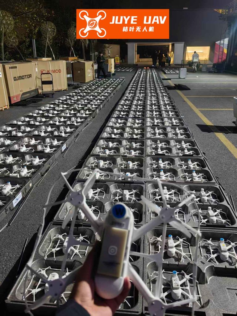
The visual impact of a formation drone light show relies entirely on the precision achieved by such mathematical formulations and their robust implementation across the fleet. The geometric clarity seen in the image is a direct result of solving the formation control problem.
| Target Pattern | Parameters (a, b, \( r_i \), \( \beta_i \)) | Resulting Coordinates (relative to centroid) |
|---|---|---|
| Horizontal Line (N drones, spacing d) | a=1, b=1, \( r_i = (i – \frac{N+1}{2})d \), \( \beta_i \in \{0, \pi\} \) | \( ( \pm r_i, 0 ) \) |
| Circle (N drones, radius R) | a=1, b=1, \( r_i = R \), \( \beta_i = \frac{2\pi (i-1)}{N} \) | \( ( R\cos(\beta_i), R\sin(\beta_i) ) \) |
| Elliptical Ring | a=2, b=1, \( r_i = R \), \( \beta_i = \frac{2\pi (i-1)}{N} \) | \( ( aR\cos(\beta_i), bR\sin(\beta_i) ) \) |
| Spiral | a=1, b=1, \( r_i = R_0 + c \cdot i \), \( \beta_i = k \cdot r_i \) | \( ( r_i \cos(\beta_i), r_i \sin(\beta_i) ) \) |
TIC_Ad_Hoc: A Scheduled Communication Protocol for Collision Avoidance
The reliable execution of a formation drone light show depends on a stable communication network. A pure mobile ad-hoc network (MANET) allows drones to communicate directly with each other without infrastructure, but its decentralized nature introduces two major problems for dense formations: 1) Unbounded Channel Access Contention: If many drones need to broadcast status packets simultaneously (e.g., at a fixed control rate), Carrier Sense Multiple Access with Collision Avoidance (CSMA/CA) mechanisms can break down, leading to high collision rates, packet loss, and increased latency. 2) Dynamic Topology Instability: Rapid movement can cause frequent link breaks and route rediscovery, consuming bandwidth and processing power.
We propose the Time-Indexed Circular Ad-Hoc (TIC_Ad_Hoc) protocol to solve the collision problem. TIC_Ad_Hoc imposes a lightweight, global time-division structure on the network while retaining the self-organizing benefits of Ad-Hoc routing for data forwarding.
Core Mechanism: The protocol divides time into repeating cycles of fixed duration \( T_{cycle} \). Each cycle is subdivided into \( N \) equal-duration time slots, where \( N \) is greater than or equal to the maximum number of drones in the fleet. A global clock is synchronized across all drones using protocols like GPS Pulse-Per-Second (PPS) or precision time protocol (PTP). Each drone is assigned a unique, static slot index \( s \in \{0, 1, …, N-1\} \). The fundamental rule is: A drone is only permitted to initiate a broadcast transmission during its assigned time slot within each cycle.
The mapping of drone ID to slot index can be a simple hash function or a pre-configured lookup table. The slot duration \( T_{slot} = T_{cycle}/N \) is designed to be long enough to transmit one or several packets (state update, neighbor info) but short enough to keep the control loop latency low. For a 100-drone show with a 20 Hz control update rate, \( T_{cycle} = 50ms \). If \( N = 128 \) (providing spare slots), \( T_{slot} \approx 390\mu s \), which is sufficient for a small packet.
The scheduled access eliminates contention and collisions during the initial transmission of periodic control data, which is the most critical traffic in a formation drone light show. The timing structure is illustrated below conceptually: drones transmit in a round-robin fashion, ensuring each has a guaranteed, interference-free window to broadcast.
Network Layer Operation: The TIC_Ad_Hoc protocol operates primarily at the MAC layer. For unicast or multi-hop data (e.g., non-time-critical commands, software updates), the network can still use standard Ad-Hoc routing protocols (e.g., OLSR, AODV), but these packets are also queued for transmission during the node’s own scheduled slot to maintain the no-collision guarantee. This hybrid approach combines the predictability of TDMA with the flexibility of MANET routing.
Synchronization and Robustness: Robust time synchronization is critical. We use a two-tier approach: 1) Global Absolute Time Sync: All drones synchronize their clocks to a common source (GPS) at startup and periodically. 2) Local Relative Adjustment: Within the formation, drones periodically exchange timestamps in their assigned slots to correct for small clock drifts using consensus algorithms. A guardian timer mechanism allows a drone to reclaim a slot if it detects it has been silent for multiple cycles (indicating a possible failure), enhancing robustness.
The benefits of TIC_Ad_Hoc for a formation drone light show are quantifiable:
- Deterministic Latency: The worst-case latency for a broadcast from any drone to be heard by all one-hop neighbors is bounded by one cycle period \( T_{cycle} \).
- Zero Packet Collision for Scheduled Traffic: Eliminates the primary cause of packet loss in dense deployments.
- Predictable Bandwidth: Network capacity is stable and calculable, facilitating system design.
- Energy Efficiency: Drones can power down their radios outside their transmit/receive windows, saving battery.
| Protocol Type | Channel Access | Collision Probability | Latency | Topology Adaptability | Suitability for Dense Formation |
|---|---|---|---|---|---|
| Standard WiFi (CSMA/CA) | Contention-Based | High (increases with N) | Unbounded, Variable | High | Poor |
| Classic MANET (AODV/OLSR) | Contention-Based | High | Variable | Very High | Poor |
| Centralized TDMA (Ground Station) | Scheduled (Centralized) | None | Low, Fixed | None (Star Topology) | Limited (Scalability) |
| TIC_Ad_Hoc (Proposed) | Scheduled (Distributed) | None for Scheduled Traffic | Bounded, Fixed | High | Excellent |
System Integration and Performance Considerations
Integrating the precise quadrotor dynamics model, the parametric formation controller, and the TIC_Ad_Hoc communication protocol creates a complete system stack for a professional formation drone light show. The operational flow can be described as follows:
- Pre-flight Planning: The show sequence is designed offline. For each animation frame or keyframe, the formation parameters \( (x_0, y_0, z_0, \alpha, a, b) \) and the list of \( (r_i, \beta_i) \) for each drone are computed. This trajectory data is compressed and uploaded to all drones, or to a subset of leader drones.
- Network Initialization: Drones power on, acquire GPS lock for time and position synchronization, and initialize the TIC_Ad_Hoc network. They broadcast their ID and slot assignment in a dedicated initialization phase to establish neighbor tables.
- Takeoff and Formation Assembly: Drones take off to a holding altitude. Using the formation controller, they navigate to their initial position in the first pattern, relying on their own trajectory calculation and neighbor-relative measurements (from onboard sensors like UWB for fine positioning) to compensate for any initial errors.
- Show Execution: The show clock starts. Each drone follows its pre-computed reference trajectory \( \mathbf{p}_{d,i}(t) \). The local flight controller uses the dynamic model to compute motor commands \( U_{1..4} \) to track this trajectory. Simultaneously, in its assigned TIC_Ad_Hoc time slot, it broadcasts a short status packet containing its current estimated position, velocity, and health data. Neighboring drones receive this data, which can be used for decentralized formation-keeping algorithms (e.g., consensus-based correction) to mitigate the accumulation of individual tracking errors, ensuring the formation drone light show remains crisp.
- Dynamic Response: If a drone detects a critical failure (e.g., motor fault, low battery), it broadcasts an emergency message in its slot and executes a pre-programmed safety maneuver (e.g., fly away and land). Neighbors receiving this message can adjust the formation parameters in real-time to “close the gap,” or a ground operator can intervene via the Ad-Hoc command channel.
Simulation and Experimental Validation: We validated this integrated approach through high-fidelity multi-agent simulations (e.g., in MATLAB/Simulink or ROS/Gazebo). The simulation incorporated the non-linear drone dynamics, the formation controller, and a network simulator modeling packet loss and latency. Comparative tests between a standard CSMA/CA network and the TIC_Ad_Hoc network for a 50-drone circular formation showed dramatic improvement. Under CSMA/CA, as the broadcast rate increased above 10 Hz, packet delivery ratio (PDR) plummeted below 70%, causing visible formation jitter and drift. The TIC_Ad_Hoc network maintained a PDR of ~99.9% at 20 Hz, resulting in perfectly stable formation tracking. These results underscore that reliable communication is not just a supporting system but the central nervous system enabling a flawless formation drone light show.
The scalability of this framework is primarily limited by the radio range and the cycle time \( T_{cycle} \). For shows with over 1000 drones, a hierarchical or clustered TIC_Ad_Hoc approach can be employed, where drones within a cluster share a slot sub-structure, and cluster heads communicate on a separate schedule. This preserves the collision-free guarantee while managing the slot assignment complexity.
In conclusion, the advancement of formation drone light show technology hinges on addressing the intertwined problems of control and communication with equal rigor. By grounding the formation in a parametric mathematical model and enforcing disciplined, time-scheduled network access, we create a system where artistic vision can be realized with engineering precision and reliability. The proposed TIC_Ad_Hoc protocol, by eliminating the randomness of contention-based access, provides the deterministic foundation required for the large-scale, complex aerial choreography that defines the future of this field.