
The pursuit of autonomous drone formation flight represents a significant frontier in unmanned aerial systems, driven by applications in surveillance, mapping, cargo delivery, and aerial displays. Formation flying, defined as the coordinated flight of multiple drones maintaining a specific spatial and organizational pattern, enhances overall system capability, efficiency, and redundancy. Among various control paradigms, the leader-follower architecture remains predominant for its conceptual simplicity and practical implementability. However, a persistent gap exists between promising simulation results and reliable real-world performance, often due to unmodeled dynamics, communication delays, and the challenges of aggressive maneuvers. This work details the comprehensive design, optimization, and, crucially, the successful flight test validation of a formation control system for small, fixed-wing drones, addressing these practical hurdles.
The core challenge in drone formation control is to synthesize laws that are not only mathematically sound but also compatible with the limited computational resources and existing autopilot modes of small UAV platforms. Our approach decomposes the three-dimensional control problem into longitudinal, lateral, and vertical channels, leveraging the inherent structure of conventional autopilots. Furthermore, we introduce a critical enhancement using a Line-of-Sight (LOS) guidance method during significant leader heading changes, such as turns, to prevent degradation in formation tracking accuracy. The complete system was implemented and tested on a fleet of small fixed-wing drones, demonstrating robust performance in maintaining precise formation geometry throughout autonomous flight missions.
1. Fundamentals of Leader-Follower Formation Kinematics
The foundation of our controller design is the relative kinematics between the leader (L) and wing (W) drones. We define a wing-fixed reference frame. The x-axis of this frame is aligned with the wing’s velocity vector, the y-axis is perpendicular to x in the horizontal plane (positive to the right), and the z-axis completes the right-handed system downwards. In this frame, the relative motion of the leader with respect to the wing is described by the following nonlinear equations:
$$ \frac{dx}{dt} = \dot{\psi}_W y – V_W + V_L \cos(\psi_e) $$
$$ \frac{dy}{dt} = -\dot{\psi}_W x + V_L \sin(\psi_e) $$
where \( (x, y) \) is the leader’s position in the wing’s frame, \( V_L \) and \( V_W \) are the leader and wing airspeeds, \( \psi_L \) and \( \psi_W \) are their heading angles, and \( \psi_e = \psi_L – \psi_W \) is the heading error.
Given a desired formation geometry defined by constant offsets \( (x_r, y_r, H_r) \) in the leader’s body frame (e.g., \( x_r = -10\text{m}, y_r = 0\text{m} \) for a trail formation), the wing’s desired states in the global North-East-Down (NED) inertial frame are continuously computed from the leader’s real-time telemetry:
$$ X_{W,des} = X_L – x_r \cos(\psi_L) + y_r \sin(\psi_L) $$
$$ Y_{W,des} = Y_L – x_r \sin(\psi_L) – y_r \cos(\psi_L) $$
$$ V_{W,des} = V_L $$
$$ \psi_{W,des} = \psi_L $$
$$ H_{W,des} = H_L – H_r $$
Here, \( (X_{W,des}, Y_{W,des}, V_{W,des}, \psi_{W,des}, H_{W,des}) \) is the wing’s desired state, and \( (X_L, Y_L, V_L, \psi_L, H_L) \) is the leader’s current state. The control objective is to drive the wing’s actual state to this desired state. The position errors in the wing’s horizontal frame are found by calculating the range \( D \) and bearing \( \beta \) to the desired point:
$$ \alpha = \arctan2\left( Y_{W,des} – Y_W, X_{W,des} – X_W \right) $$
$$ \beta = \alpha – \psi_W $$
$$ D = \sqrt{ (X_{W,des} – X_W)^2 + (Y_{W,des} – Y_W)^2 } $$
$$ \Delta x = D \cos(\beta) – x_r $$
$$ \Delta y = D \sin(\beta) – y_r $$
$$ \Delta V = V_L – V_W $$
$$ \Delta \psi = \psi_L – \psi_W $$
$$ \Delta H = (H_L – H_r) – H_W $$
The control goal is to achieve \( (\Delta x, \Delta y, \Delta V, \Delta \psi, \Delta H) \rightarrow (0, 0, 0, 0, 0) \).
2. Decoupled Formation Controller Architecture
To integrate seamlessly with standard autopilot functionalities, the formation controller is partitioned into three independent channels. This decoupling simplifies design and tuning. The following table summarizes the control architecture:
| Control Channel | Primary Error States | Autopilot Mode Used | Generated Command |
|---|---|---|---|
| Longitudinal | \(\Delta x\), \(\Delta V\) | Airspeed Hold | \(V_{W,cmd}\) |
| Lateral | \(\Delta y\), \(\Delta \psi\) | Route Following / Roll Attitude | \(\phi_{W,cmd}\) (via \(\psi_{W,cmd}\)) |
| Vertical | \(\Delta H\) | Altitude Hold | \(H_{W,cmd}\) |
2.1 Longitudinal Channel Controller
The longitudinal controller manages the forward separation and speed matching. A combined error is constructed from the along-track position error \(\Delta x\) and the velocity error \(\Delta V\):
$$ e_x = k_{x} \Delta x + k_{V} \Delta V $$
This error is fed into a PI controller to generate the commanded airspeed for the wing’s autopilot:
$$ V_{W,cmd} = k_{P}^{V} e_x + k_{I}^{V} \int_{0}^{t} e_x \, d\tau $$
The integral action helps eliminate steady-state errors caused by wind or slight aerodynamic differences between drones in the formation.
2.2 Lateral Channel Controller
The lateral controller is designed for simplicity by utilizing the drone’s native “route following” mode. In this mode, the autopilot accepts a desired heading command and automatically generates the necessary roll angle to track it. The formation controller generates this desired heading command as a weighted combination of cross-track error \(\Delta y\) and heading error \(\Delta \psi\):
$$ \psi_{W,cmd} = k_{y} \Delta y + k_{\psi} \Delta \psi $$
This approach effectively simplifies the lateral control design to tuning two gains, as the low-level roll dynamics and stability augmentation are handled by the proven autopilot logic.
2.3 Vertical Channel Controller
The altitude channel uses a standard PI controller on the altitude error \(\Delta H\):
$$ H_{W,cmd} = k_{P}^{H} \Delta H + k_{I}^{H} \int_{0}^{t} \Delta H \, d\tau $$
The output \(H_{W,cmd}\) is sent directly to the altitude hold mode of the wing’s autopilot.
3. Enhanced Control for Dynamic Maneuvers: LOS-Based Optimization
While the decoupled controller works well for steady flight and gentle maneuvers, a significant weakness is exposed during aggressive leader turns. The wing must rapidly change both heading and speed to cut the corner and maintain position. The speed channel, governed by a slower PI controller, cannot react swiftly enough, leading to large transient errors. To address this, we augment the lateral and longitudinal control laws with a Line-of-Sight (LOS) guidance scheme specifically activated during high heading-rate maneuvers.
When the leader’s heading change exceeds a threshold, the controller switches logic. First, it computes the line-of-sight vector from the wing’s current position to its desired position:
$$ \rho_{WL} = \sqrt{ (X_{W,des} – X_W)^2 + (Y_{W,des} – Y_W)^2 } $$
$$ \chi_{WL} = \arctan2\left( Y_{W,des} – Y_W, X_{W,des} – X_W \right) $$
Here, \( \rho_{WL} \) is the horizontal distance to the target, and \( \chi_{WL} \in (-\pi, \pi] \) is the LOS angle.
The core idea is to command the wing to fly directly towards the instantaneous desired point. The commanded heading becomes the LOS angle:
$$ \psi_{W,cmd} = \chi_{WL} $$
Simultaneously, the speed command is dynamically adjusted based on the remaining distance to ensure the wing can decelerate to match the leader’s speed upon reaching the formation point. We define a threshold distance \( \Delta_{WL} \):
$$ \Delta_{WL} = \frac{(V_{W,max} – V_L)^2}{2 a_{W,min}} $$
where \( V_{W,max} \) is the wing’s maximum airspeed and \( a_{W,min} \) is its maximum deceleration capability (a negative acceleration). This \( \Delta_{WL} \) represents the distance required for the wing to slow down from its maximum speed to the leader’s speed.
The speed command logic is then:
$$ V_{W,cmd} =
\begin{cases}
V_{W,max}, & \text{if } (\Delta_{WL} + 2\delta_{safe}) < \rho_{WL} \\
V_L + \frac{\rho_{WL} – \delta_0}{\Delta_{WL} + 2\delta_{safe}} \sqrt{2 a_{W,min} \delta_{safe}}, & \text{if } (\Delta_{WL} + 2\delta_{safe}) \ge \rho_{WL}
\end{cases} $$
where \( \delta_{safe} \) is a safety distance buffer, and \( \delta_0 \) is the allowed final steady-state error. This law commands maximum speed if the wing is far away, and smoothly reduces the commanded speed as it approaches the desired position, ensuring a stable merge into the formation slot without overshoot.
4. Flight Test System and Platform
The validation of drone formation control laws necessitates a robust hardware and software ecosystem. Our test platform was built around commercially available small fixed-wing airframes, modified for full autonomy and data sharing.
4.1 Drone Platform Specifications
The drone platform was a small, electric-powered fixed-wing aircraft. Key parameters are summarized below:
| Parameter | Value |
|---|---|
| Wingspan | 2.0 m |
| Length | 1.8 m |
| Empty Weight | 1.2 kg |
| Max Takeoff Weight | 2.1 kg |
| Cruise Speed | 10 m/s |
| Endurance | 8-10 minutes |
| Propulsion | Twin electric motors |
Each aircraft was equipped with a crucial suite of avionics: a high-quality GPS/INS module for precise position and attitude estimation; a digital data link for commanding and telemetry; and a dedicated flight control computer running the open-source ArduPilot autopilot software. The autopilot provided all the low-level stabilization and control modes (e.g., Stabilize, Altitude Hold, Loiter, Return-to-Launch) upon which our formation controllers were layered.
4.2 System Architecture for Formation Flight
The system followed a distributed architecture. The leader drone flew a pre-programmed mission autonomously. Its state (position, velocity, heading, altitude) was broadcast via the data link at 10 Hz. The wing drone(s) received this data on their onboard companion computers (a Raspberry Pi or similar). The formation control algorithms, as described in Sections 2 and 3, ran on this companion computer. Using the received leader data and its own state, the wing’s computer calculated the error states and generated the appropriate commands \( (V_{cmd}, \psi_{cmd}, H_{cmd}) \). These commands were then sent to the wing’s autopilot via a serial interface, effectively acting as a high-level guidance system. A ground control station monitored the telemetry from all drones in real-time.
4.3 Flight Test Scenario
A standard racetrack pattern was used for testing, consisting of waypoints for takeoff, climb, cruise, turns, and landing. For the formation test segment, the leader would enter a straight-and-level cruise leg. The wing drone, initially flying a separate but parallel safe path, would then engage the formation controller. The desired formation was a classic trail configuration with the wing positioned 10 meters directly behind the leader \( (x_r = -10\text{m}, y_r = 0\text{m}, H_r = 0\text{m}) \). The formation was maintained through multiple turns of the racetrack pattern before the wing was commanded to disengage and land independently.
5. Flight Test Results and Analysis
Multiple flight tests were conducted to validate the baseline and enhanced formation controllers. The primary metrics for assessment were the steady-state tracking errors and the transient behavior during turns.
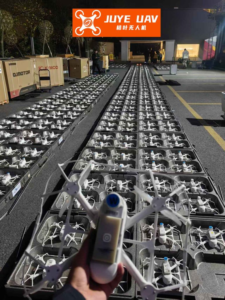
The figure above conceptually illustrates the goal of precise spatial coordination achieved in our tests, akin to a tightly controlled drone light show but with fixed-wing aircraft performing dynamic flight paths.
5.1 Steady-State Performance
During straight-level flight segments, the decoupled controller demonstrated excellent performance. The wing successfully acquired and maintained the prescribed 10-meter trail position. The altitude and heading tracking were particularly precise, with errors converging to near zero. The airspeed control showed slightly more variation due to atmospheric turbulence and the inherent lag in the propulsion system’s response, but maintained close proximity to the leader’s speed. A sample of recorded steady-state error statistics from a typical flight is shown below:
| Error Metric | Mean Value | Standard Deviation |
|---|---|---|
| \(\Delta x\) (Along-Track) | -0.25 m | 0.8 m |
| \(\Delta y\) (Cross-Track) | 0.1 m | 0.5 m |
| \(\Delta H\) (Altitude) | -0.3 m | 0.4 m |
| \(\Delta \psi\) (Heading) | 0.5° | 1.8° |
5.2 Performance During Turns: Baseline vs. Enhanced Controller
The most revealing tests involved leader turns with a bank angle of approximately 25-30 degrees. With the baseline (decoupled) controller, a predictable issue occurred. As the leader turned, the wing’s desired position moved along an arc. The wing’s lateral controller reacted quickly to the changing \(\Delta y\) and \(\Delta \psi\), commanding a turn. However, its longitudinal controller failed to increase speed sufficiently or in time, causing the wing to lag behind. This resulted in a large increase in \(\Delta x\) (the wing fell behind) and a corresponding overshoot in \(\Delta y\) as it tried to “catch the corner.” Upon exit from the turn, the opposite problem occurred: the wing now needed to slow down, leading to oscillatory behavior as the speed PI controller corrected the error.
In contrast, the enhanced LOS-based controller showed markedly superior performance. When the leader’s turn was detected, the wing immediately switched to heading-toward-the-desired-point guidance. It commanded a near-maximum speed to aggressively close the distance, following a more direct chord-like path across the leader’s turning circle. As it approached the desired position, the speed modulation law smoothly reduced the command, allowing the wing to slot back into the formation geometry smoothly as the leader finished the turn. The transient errors in \(\Delta x\) and \(\Delta y\) were significantly reduced in magnitude and duration.
The following equation and description encapsulate the key improvement. The baseline controller effectively tries to solve two separate, slower problems: “turn to match heading” and “adjust speed to match position.” The LOS controller solves a single, more direct problem: “fly directly to the target point at an appropriate speed.” The commanded heading is the solution to the geometric guidance problem:
$$ \psi_{cmd}^{LOS} = \arctan2\left( Y_{des}(t) – Y_W, X_{des}(t) – X_W \right) $$
This reactive guidance inherently accounts for the coupled nature of the maneuver, leading to more efficient and stable drone formation tracking during dynamics.
6. Conclusion and Future Work
This work has presented a practical and flight-validated approach to autonomous drone formation control for small fixed-wing UAVs. By decomposing the control problem into longitudinal, lateral, and vertical channels aligned with standard autopilot modes, we developed an easily implementable system. The critical innovation was the integration of a Line-of-Sight guidance law to handle the challenging case of formation keeping during aggressive leader maneuvers. The flight test results conclusively demonstrated that this enhanced controller maintains significantly better formation accuracy through turns compared to a standard decoupled approach, without adding undue complexity.
The success of these tests provides a strong foundation for several avenues of future research. First, scaling the system to larger formations with multiple wing drones, which introduces inter-agent communication and potential collision avoidance constraints. Second, integrating more sophisticated aerodynamic models, such as wake interaction effects between closely spaced fixed-wing drones, which could be exploited for energy-saving purposes in extended endurance drone formation flights. Third, implementing and testing fully decentralized coordination strategies where the “leader” role can be dynamic or virtual. Finally, extending the system to operate in GPS-denied environments using vision-based or relative navigation techniques would greatly enhance its robustness and applicability. The demonstrated system serves as a crucial step towards reliable and versatile autonomous drone formation capabilities for real-world applications.