
In recent years, the advancement of virtual reality (VR) technology has revolutionized simulation systems, enabling the creation of immersive artificial environments that leverage the “3I” features—immersion, interaction, and imagination. This has profound implications for complex systems like drone formation flying, where real-world experiments entail high costs and significant risks. Traditional scene development tools, such as OpenGL, often suffer from poor code portability and low execution efficiency, prompting the need for more robust solutions. In this context, we propose a virtual validation platform based on Vega, a high-performance visual simulation toolkit, to address these challenges. This platform integrates Vega’s 3D model driving capabilities with the flexible control of Microsoft Foundation Classes (MFC), facilitating efficient drone formation flying scene simulation. The primary goal is to develop a system that offers high fidelity, real-time performance, strong portability, and reliable data transmission, thereby enabling cost-effective and risk-free testing of drone formation algorithms and flight scenarios.
The core motivation stems from the inherent difficulties in conducting real drone formation experiments, which involve multiple unmanned aerial vehicles (UAVs) operating in coordination. Such experiments are not only expensive but also pose safety hazards, especially in dynamic environments. By leveraging VR, we can simulate these scenarios in a controlled virtual setting, allowing for extensive testing and validation. Our focus is on the scene simulation system, which serves as the end-user interface for human-computer interaction, rendering 3D animations from numerical data to enhance realism and interpretability. This article delves into the key technologies involved, including system architecture, data communication, view segmentation, real-time control and display, and data recording and playback, all centered around the theme of drone formation. We emphasize the use of tables and formulas to succinctly summarize critical aspects, ensuring a comprehensive understanding of the simulation platform.
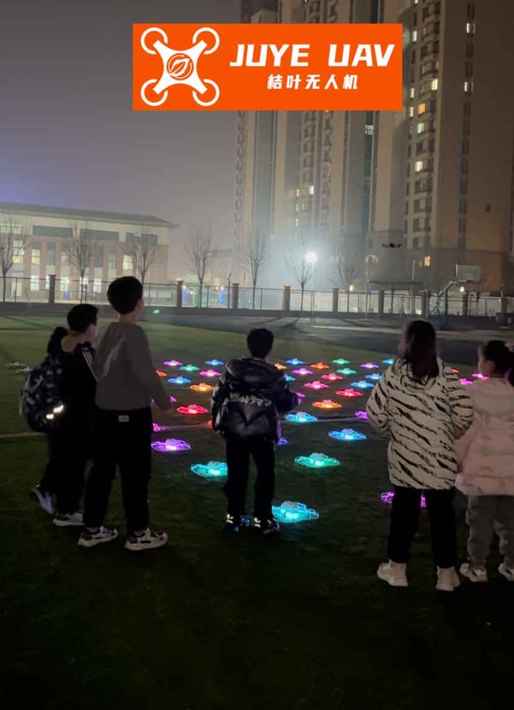
The simulation of drone formation flying places stringent demands on real-time performance, as any lag in rendering can break the sense of immersion and hinder effective interaction. Real-time requirements encompass the dynamic updating of positions and attitudes for each drone in the formation, seamless frame rendering without perceptible flicker (typically above 30 frames per second), and prompt responses to user inputs. To achieve this, we adopt a distributed architecture that offloads computational burdens from the visual display system. Specifically, each drone in the formation is assigned a dedicated simulation computer responsible for solving its flight dynamics model and generating trajectory data. These computers are interconnected via a high-speed switch, enabling rapid data exchange essential for multi-drone coordination. The visual simulation and control computer acts as a central hub, managing initial parameters, orchestrating the drone formation, forwarding critical flight data among drones, and rendering the 3D scene. This setup ensures that the visual system remains responsive, even with complex drone formation scenarios involving numerous entities.
| Requirement | Description | Target Metric |
|---|---|---|
| Real-time Rendering | Dynamic update of drone positions and attitudes with no visible lag | Frame rate ≥ 30 Hz |
| Data Communication | Low-latency, reliable transmission of flight data among distributed nodes | Latency < 10 ms, packet loss < 2% |
| System Portability | Code adaptability across different hardware and software environments | Platform-independent implementation |
| Human-Computer Interaction | Intuitive controls for simulation management and viewpoint adjustment | Response time < 100 ms |
| Data Recording | Efficient storage of flight data for post-simulation analysis and replay | File size optimized, read/write speed high |
The overall system architecture is designed to meet these requirements, as illustrated in the distributed framework. Each drone simulation computer runs an instance of the flight dynamics model, calculating state vectors for its assigned drone. These vectors, denoted as \( \mathbf{P}_k = [x_k, y_k, z_k, h_k, p_k, r_k] \) for drone \( k \), include three-dimensional coordinates \( (x_k, y_k, z_k) \) and orientation angles (heading \( h_k \), pitch \( p_k \), roll \( r_k \)). The visual computer aggregates these vectors, converts them into appropriate formats, and drives the 3D models in the scene. This separation of concerns not only enhances real-time performance but also allows for scalable drone formation simulations, where additional drones can be integrated by merely adding more simulation computers. The communication between nodes relies on the User Datagram Protocol (UDP), chosen for its low overhead and suitability for real-time data streaming, albeit with mechanisms to handle potential data loss or corruption.
To implement the scene simulation system, we follow a structured workflow that combines modeling, configuration, and programming. Initially, 3D models of the drones and environment are created using Multigen-Creator, a specialized tool for building realistic virtual assets. These models are then imported into Vega’s graphical user interface, LynX, where initial scene configurations—such as lighting, terrain, and camera settings—are defined. This generates an Application Definition File (ADF), which serves as a blueprint for the simulation. Subsequently, we develop the application using Visual C++ with MFC, integrating Vega’s API libraries to drive the models and render the scene. The MFC framework provides a robust foundation for building the user interface, utilizing the document/view architecture to organize data and views efficiently. We employ a single-document interface, with the view class derived from Vega’s custom class to facilitate seamless integration. The simulation operates in two modes: demonstration (file-based) and simulation (network-based), allowing for flexibility in data sourcing.
The system framework, as depicted, encompasses several modules: terrain and drone model loading, dynamic effects generation, data acquisition from network or files, decoding, and real-time rendering. A key aspect is the view segmentation, where the main window is divided into three distinct areas: the scene display area for 3D visualization, the data display area for numerical readouts, and the control area for user inputs. This is achieved through MFC’s CSplitterWnd class, which enables the creation of multiple panes within a single window. For instance, the Vega view is embedded as a child pane, inheriting from a specialized Vega view class to handle rendering tasks. Communication between these views is essential; for example, the control view sends commands to the Vega view to start or pause the simulation. This is managed by obtaining pointers to the respective view classes and invoking appropriate methods, ensuring synchronized interaction across the interface.
| Component | Role | Key Functions |
|---|---|---|
| Drone Simulation Computers | Individual flight dynamics computation | Solve equations of motion, generate state vectors |
| Visual Simulation Computer | Central rendering and control | Aggregate data, drive 3D scene, provide UI |
| High-speed Switch | Network connectivity | Facilitate UDP data exchange among nodes |
| Vega API Libraries | 3D graphics rendering | Model driving, scene management, special effects |
| MFC Framework | User interface development | Window management, event handling, view segmentation |
One of the critical technologies in drone formation flying scene simulation is data communication. Given the real-time nature of the system, we utilize UDP for its speed and efficiency, despite its lack of guaranteed delivery. Each data packet transmitted over the network contains a header and payload, with the header comprising 8 bytes of control information and the payload carrying the actual flight data. To mitigate issues like packet loss or errors, we implement two validation methods: length checks and data consistency checks. The length check verifies that the received packet size matches the expected size based on the predefined data format, helping assess the packet loss rate. The data consistency check involves initializing decoded data to default values; if the data remains unchanged after decoding, it is deemed invalid and discarded, thus estimating the bit error rate. This approach ensures that the drone formation simulation maintains data integrity, with typical loss rates below 2% and error rates near zero in local area networks.
The data packet structure can be represented as follows: let \( D \) be the total packet length, \( H \) the header of 8 bytes, and \( P_k \) the payload for drone \( k \). The payload includes the state vector \( \mathbf{P}_k \), and the packet for a formation of \( n \) drones is concatenated as \( [H, P_1, P_2, \dots, P_n] \). The length check ensures that \( D = 8 + \sum_{k=1}^n \text{len}(P_k) \), where \( \text{len}(P_k) \) is the byte size of each drone’s data. For data consistency, we set initial values \( \mathbf{P}_k^{\text{init}} \) and compare after decoding; if \( \mathbf{P}_k = \mathbf{P}_k^{\text{init}} \), the packet is rejected. This simple yet effective mechanism supports reliable communication in drone formation simulations.
Another pivotal technology is the segmentation of Vega sub-views within the MFC application. By using the CSplitterWnd class, we partition the main view into a data display area and a split view area, with the latter further divided into control and scene display areas. This irregular splitting is achieved through nested calls to the GetPane method, which retrieves pointers to specific panes based on row and column indices. For example, to access the Vega view from the control view, we first obtain the main frame pointer, then the splitter window pointer, and finally the Vega view pointer through type casting. This enables inter-view communication, such as sending simulation control commands. The Vega view, derived from a base Vega class, overrides virtual functions to customize rendering and update cycles, ensuring that the drone formation is displayed accurately in its dedicated pane. This design enhances the user experience by providing a comprehensive interface that combines visual feedback with interactive controls.
Real-time control and display are paramount for immersive drone formation simulation. Beyond rendering drone positions and attitudes, the system incorporates various control interfaces, including simulation pause/resume, visual effects adjustment, data reception frequency tuning, and viewpoint manipulation. The viewpoint control allows users to observe the drone formation from different perspectives, such as following a specific drone or adopting a fixed camera angle. Mathematically, the viewpoint transformation is modeled using spherical coordinates relative to a target drone. Suppose we focus on drone \( k \) with position \( O(x_k, y_k, z_k) \) in world coordinates. The observer’s position \( P \) is defined by a distance \( l \), an azimuthal angle \( \alpha \) relative to the y-axis, and an elevation angle \( \beta \) relative to the horizontal plane. When the observer moves left or right, the position updates along a horizontal circle centered at \( O \). Let \( \Delta l \) be the horizontal movement speed. At time step \( t_{k+1} \), the new observer coordinates are given by:
$$ x_{k+1} = x_k – \Delta l \sin \alpha $$
$$ y_{k+1} = y_k – \Delta l \cos \alpha $$
$$ z_{k+1} = z_k $$
Here, \( \alpha = \pi – h \), where \( h \) is the observer’s heading relative to the target. The corresponding azimuthal angle update is:
$$ \alpha_{k+1} = \pi – \arctan\left(\frac{\Delta l}{\sqrt{x_k^2 + y_k^2}}\right) $$
For vertical movement, such as moving upward by \( \Delta z \), the changes are:
$$ z_{k+1} = z_k + \Delta z $$
$$ \beta_{k+1} = \arctan\left(\frac{z_{k+1}}{\sqrt{x_k^2 + y_k^2}}\right) $$
These equations ensure smooth viewpoint transitions, enhancing the realism of the drone formation visualization. Additionally, we implement text rendering via Vega’s callback mechanism to overlay flight data on the screen. While Vega’s vgDrawFont() function supports single-line text, we develop a custom OpenGL-based class to draw multi-line strings, parsing newline characters for formatted displays. This is crucial for showing real-time metrics like drone speeds, altitudes, and formation patterns. Furthermore, we animate drone components, such as tail fins, using Vega’s degree-of-freedom nodes, which update based on the orientation angles \( (h_k, p_k, r_k) \) to reflect actual flight dynamics.
| Movement | Parameter | Update Formula | Notes |
|---|---|---|---|
| Horizontal Left | Observer position \( (x, y) \) | \( x_{k+1} = x_k – \Delta l \sin \alpha \), \( y_{k+1} = y_k – \Delta l \cos \alpha \) | \( \alpha = \pi – h \), circular motion |
| Horizontal Right | Observer position \( (x, y) \) | \( x_{k+1} = x_k + \Delta l \sin \alpha \), \( y_{k+1} = y_k + \Delta l \cos \alpha \) | Similar to left, direction reversed |
| Vertical Up | Observer height \( z \) and elevation \( \beta \) | \( z_{k+1} = z_k + \Delta z \), \( \beta_{k+1} = \arctan(z_{k+1} / \sqrt{x_k^2 + y_k^2}) \) | Height change only, angles recalculated |
| Vertical Down | Observer height \( z \) and elevation \( \beta \) | \( z_{k+1} = z_k – \Delta z \), \( \beta_{k+1} = \arctan(z_{k+1} / \sqrt{x_k^2 + y_k^2}) \) | Mirrors upward movement |
Data recording and playback are essential for post-simulation analysis and training purposes. We define a custom file format called FTD (Formation Telemetry Data) to store flight information. The FTD file consists of two parts: a header and a body. The header is an 11-byte structure containing metadata to identify the file and describe the simulation parameters, while the body holds the sequential flight data for all drones in the formation. The header structure includes fields such as file type, number of drones, coordinate system flag, and reference drone index for relative coordinates. Specifically, the file type is encoded as a WORD value ‘FD’ to ensure unique identification. During recording, we avoid writing data in the rendering thread to prevent frame rate drops; instead, a timer periodically writes received data to disk. The storage process involves capturing state vectors from the network or simulation, encoding them into the FTD format, and appending them to the file. For playback, the header is read first to configure the scene, followed by sequential reading of data frames to drive the simulation clock, effectively recreating the drone formation flight.
| Field | Type (Bytes) | Description | Example Value |
|---|---|---|---|
| wType | WORD (4) | File type identifier | ‘FD’ (0x4644) |
| nPlaneNum | int (4) | Number of drones in formation | 3 |
| bAbs | BOOL (1) | Flag for absolute coordinates (1) or relative (0) | 1 |
| nCIndex | int (4) | Index of reference drone for relative coordinates | 0 (first drone) |
The recording workflow can be summarized as: data acquisition → buffering → periodic file writing. Let \( \mathbf{P}_k(t) \) represent the state vector of drone \( k \) at time \( t \). The recorded data for a time step \( t_i \) is a concatenated array \( [\mathbf{P}_1(t_i), \mathbf{P}_2(t_i), \dots, \mathbf{P}_n(t_i)] \), stored sequentially in the FTD body. During playback, the system reads these arrays and updates the scene accordingly, enabling users to review the drone formation mission from any angle. This functionality is invaluable for debugging and evaluating formation algorithms, as it allows repeated inspection of critical maneuvers without rerunning the entire simulation.
To validate our virtual platform, we conducted simulations involving a three-drone formation flying in a coordinated pattern. The data was generated from a simple virtual leader-follower model, where one drone acts as a leader and others follow with predefined offsets. The visual system successfully received and displayed the data, with frame times ranging from 0.016 to 0.02 seconds (50–60 Hz), meeting real-time requirements. Communication metrics showed a packet loss rate below 2% and zero bit errors, confirming the reliability of the UDP-based data exchange. The interface provided smooth viewpoint control, allowing observers to track individual drones or view the entire formation from panoramic perspectives. Text rendering effectively overlaid information such as drone IDs, speeds, and formation geometry, enhancing situational awareness. The recording and playback features worked flawlessly, enabling the recreation of flights for analysis. These results demonstrate the feasibility and effectiveness of our approach, highlighting the advantages of Vega and MFC integration for drone formation scene simulation.
In conclusion, the development of a virtual validation platform for drone formation flying scene simulation addresses the high costs and risks associated with real-world experiments. By leveraging Vega’s powerful 3D rendering capabilities and MFC’s flexible control framework, we have created a system that excels in fidelity, real-time performance, portability, and data reliability. Key technologies, including distributed data communication, view segmentation, real-time control algorithms, and efficient data recording, collectively ensure a robust simulation environment. The use of mathematical models for viewpoint transformation and custom file formats for data storage further enhances the system’s utility. This platform not only facilitates algorithm testing for drone formation but also serves as a training tool for operators, reducing reliance on physical prototypes. Future work may involve integrating more advanced VR devices, such as head-mounted displays, to deepen immersion, and incorporating artificial intelligence for autonomous formation control. Overall, our research underscores the potential of virtual reality in advancing drone technology, making complex formations more accessible and safer to explore.