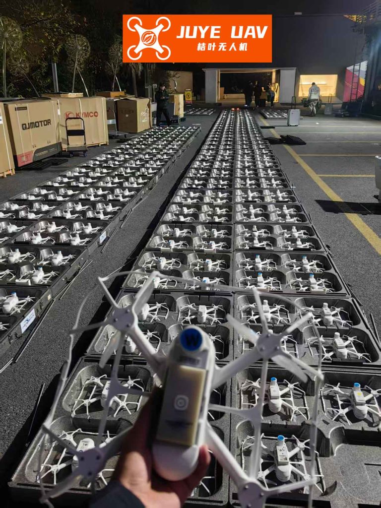
In recent years, the application of unmanned aerial vehicles (UAVs) in coordinated formations has gained significant traction, particularly in areas such as aerial displays, surveillance, and delivery systems. Among these, formation drone light shows have emerged as a captivating spectacle, where hundreds or thousands of drones synchronize their movements to create intricate patterns and animations in the night sky. However, the success of these shows heavily relies on precise navigation and coordination among the drones. Traditional navigation methods, such as relying solely on inertial navigation systems (INS), suffer from error accumulation over time, leading to degraded performance in large-scale formations. In this paper, we address these challenges by proposing a hierarchical cooperative navigation system tailored for formation drone light shows. Our approach leverages relative navigation sensors and data links to enhance the overall navigation accuracy, ensuring that the drones maintain bounded errors during extended performances. We present a detailed mathematical model, simulation results, and discuss the implications for real-world applications. Throughout this work, we emphasize the importance of robust navigation for formation drone light shows, as even minor deviations can disrupt the visual harmony of the display.
The concept of formation drone light shows involves orchestrating multiple drones to act as pixels in a dynamic canvas. Each drone must follow a predefined trajectory with high precision, often requiring centimeter-level accuracy. This is particularly challenging in outdoor environments where GPS signals may be unreliable or unavailable. Moreover, as the scale of the formation increases—such as in grand formation drone light shows involving thousands of units—the limitations of conventional master-slave cooperative navigation become apparent. In master-slave architectures, a single leader drone with high-precision navigation equipment communicates with all follower drones, but bandwidth constraints and sensor range limitations prevent effective communication and measurement in large formations. Therefore, we introduce a hierarchical structure where drones are organized in layers, akin to a tree topology, enabling scalable and efficient cooperative navigation. This structure is especially beneficial for formation drone light shows, where drones may be arranged in complex patterns and need to adapt to changing formations.
To illustrate the significance of our work, consider a typical formation drone light show where drones execute synchronized maneuvers to create shapes like logos or animations. The navigation errors must remain within tight bounds to avoid collisions and maintain visual integrity. Our hierarchical cooperative navigation system ensures this by allowing each drone to correct its INS errors using information from drones in the layer above. This not only improves accuracy but also enhances the reliability of the entire formation. In the following sections, we delve into the technical details of our approach, starting with the design of the hierarchical structure and proceeding to the mathematical formulation. We will also present simulation results that demonstrate the effectiveness of our method in scenarios relevant to formation drone light shows, such as curved trajectories and altitude variations. By integrating concepts from relative navigation and Kalman filtering, we aim to provide a comprehensive solution for next-generation formation drone light shows.
The hierarchical cooperative navigation structure is designed as a tree-like network, with a top-layer leader drone equipped with high-precision INS/GPS integration. Below this leader, multiple layers of follower drones are arranged, each carrying lower-precision INS and relative navigation sensors, such as laser rangefinders and Doppler velocity sensors. These sensors measure relative distance, azimuth, elevation, and velocity between drones in adjacent layers. Data links facilitate the exchange of navigation information, primarily from upper-layer drones to lower-layer ones. This design mitigates the bandwidth issues of master-slave systems by distributing the communication load across layers. For formation drone light shows, this means that drones can be grouped into clusters, with each cluster having its own local leader, thereby enabling seamless scaling for massive displays. The key idea is that each follower drone uses its own INS output, received navigation data from an upper-layer drone, and relative measurements to construct a measurement model for error estimation via Kalman filtering.
We now formalize the hierarchical cooperative navigation system model. Let us denote the navigation coordinate system as the geographic frame (n-frame), and the body frame of a drone as the b-frame. For any follower drone in the formation, we define the state vector to include errors from its INS. The state equation is derived from the INS error dynamics, which account for platform misalignment angles, velocity errors, position errors, and sensor biases. The system noise encompasses gyroscope and accelerometer noises. Specifically, the state vector \( X(t) \) is given by:
$$ X = [\phi_E, \phi_N, \phi_U, \delta v_E, \delta v_N, \delta v_U, \delta \lambda, \delta \phi, \delta h, \varepsilon_{bx}, \varepsilon_{by}, \varepsilon_{bz}, \varepsilon_{rx}, \varepsilon_{ry}, \varepsilon_{rz}, \nabla_x, \nabla_y, \nabla_z]^T $$
where \( \phi_E, \phi_N, \phi_U \) are the platform misalignment angles in the east, north, and up directions; \( \delta v_E, \delta v_N, \delta v_U \) are the velocity errors; \( \delta \lambda, \delta \phi, \delta h \) are the position errors in longitude, latitude, and height; \( \varepsilon_{bx}, \varepsilon_{by}, \varepsilon_{bz} \) are the constant gyro drifts; \( \varepsilon_{rx}, \varepsilon_{ry}, \varepsilon_{rz} \) are the first-order Markov gyro drifts; and \( \nabla_x, \nabla_y, \nabla_z \) are the first-order Markov accelerometer drifts. The system noise vector \( W(t) \) includes white noise processes for gyros and accelerometers. The state equation is:
$$ \dot{X}(t) = F(t) X(t) + G(t) W(t) $$
Here, \( F(t) \) is the state transition matrix derived from INS error models, and \( G(t) \) is the noise input matrix. For implementation, we discretize this equation at time intervals relevant to formation drone light shows, typically at 1-second steps.
The measurement equation for cooperative navigation is crucial for error correction. For a follower drone, the measurement vector \( Z(t) \) is constructed from the difference between computed relative navigation values (based on INS and received data) and measured relative navigation values (from sensors). Let \( p_A \) and \( v_A \) be the position and velocity of an upper-layer drone (assumed accurate after correction), and \( p_I^B \) and \( v_I^B \) be the INS-derived position and velocity of the follower drone. The computed relative position and velocity are:
$$ p_c = p_A – p_I^B, \quad v_c = v_A – v_I^B $$
The measured relative position and velocity from sensors are denoted as \( p_m \) and \( v_m \). Thus, the measurement vector is:
$$ Z = \begin{bmatrix} p_c – p_m \\ v_c – v_m \end{bmatrix} $$
Expressing the INS outputs in terms of true values and errors, we have \( p_I^B = p_t^B + \delta p_B \) and \( v_I^B = v_t^B + \delta v_B \), where \( p_t^B \) and \( v_t^B \) are the true position and velocity. Similarly, the sensor measurements include errors: \( p_m = p_t^{AB} – \delta p_m \) and \( v_m = v_t^{AB} – \delta v_m \), with \( p_t^{AB} \) and \( v_t^{AB} \) being the true relative position and velocity between drones. Substituting these into \( Z \), we get:
$$ Z = -\begin{bmatrix} \delta p_B \\ \delta v_B \end{bmatrix} + \begin{bmatrix} \delta p_m \\ \delta v_m \end{bmatrix} $$
This relationship shows that the measurement vector depends on the INS errors of the follower drone and the sensor measurement noises. To incorporate this into the Kalman filter, we need to transform the sensor measurements from the b-frame to the n-frame and convert position representations from Cartesian to geodetic coordinates.
The relative navigation sensors operate in the b-frame. For example, a laser sensor measures relative distance \( p_m^b \), elevation angle \( \alpha_m^b \), and azimuth angle \( \beta_m^b \), while a Doppler sensor measures relative velocity \( v_m^b \). These measurements are corrupted by noise:
$$ p_m^b = p_t^b + \varphi_p, \quad \alpha_m^b = \alpha_t^b + \omega_\alpha, \quad \beta_m^b = \beta_t^b + \omega_\beta, \quad v_m^b = v_t^b + \varphi_v $$
where \( \varphi_p, \omega_\alpha, \omega_\beta, \varphi_v \) are zero-mean Gaussian white noises with variances \( \sigma_p^2, \sigma_\alpha^2, \sigma_\beta^2, \sigma_v^2 \). We decompose \( v_m^b \) into b-frame components:
$$ v_{mbx} = v_m^b \cos \alpha_m^b \sin \beta_m^b, \quad v_{mby} = v_m^b \cos \alpha_m^b \cos \beta_m^b, \quad v_{mbz} = v_m^b \sin \alpha_m^b $$
Under small error assumptions, we linearize to express the measurement errors in the b-frame. For instance, the error in \( v_{mbx} \) is approximated as:
$$ \delta v_{bx} = -\varphi_v \cos \alpha_m^b \sin \beta_m^b + \omega_\alpha v_m^b \sin \alpha_m^b \sin \beta_m^b – \omega_\beta v_m^b \cos \alpha_m^b \cos \beta_m^b $$
Similar expressions hold for other components. The transformation from the b-frame to the n-frame is achieved using the direction cosine matrix \( C_b^n \), which depends on the drone’s roll (\( \gamma \)), pitch (\( \theta \)), and yaw (\( \phi \)) angles. Since the INS-provided angles are accurate, we use \( \hat{C}_b^n \approx C_b^n \). Thus, the sensor errors in the n-frame are:
$$ \begin{bmatrix} \delta p_m \\ \delta v_m \end{bmatrix} = \begin{bmatrix} \hat{C}_b^n & 0 \\ 0 & \hat{C}_b^n \end{bmatrix} \begin{bmatrix} \delta p_b \\ \delta v_b \end{bmatrix} $$
The measurement noise covariance matrix \( R \) is computed based on the variances of these errors. For position, we have:
$$ R_p = \begin{bmatrix} \text{Var}(\delta p_{me}) & \text{Cov}(\delta p_{me}, \delta p_{mn}) & \text{Cov}(\delta p_{me}, \delta p_{mu}) \\ \text{Cov}(\delta p_{mn}, \delta p_{me}) & \text{Var}(\delta p_{mn}) & \text{Cov}(\delta p_{mn}, \delta p_{mu}) \\ \text{Cov}(\delta p_{mu}, \delta p_{me}) & \text{Cov}(\delta p_{mu}, \delta p_{mn}) & \text{Var}(\delta p_{mu}) \end{bmatrix} $$
and similarly for velocity \( R_v \). The overall \( R \) is a block-diagonal matrix combining \( R_p \) and \( R_v \).
For position conversion, since drones in formation drone light shows are typically close, we approximate the Earth as flat. The computed relative position in the n-frame, \( p_c \), is expressed in terms of geodetic coordinates. Let \( \lambda_A, L_A, h_A \) be the longitude, latitude, and height of the upper-layer drone, and \( \lambda_I^B, L_I^B, h_I^B \) be the INS outputs of the follower. Then:
$$ p_c = \begin{bmatrix} (R + h_A) \cos L_A (\lambda_A – \lambda_I^B) \\ (R + h_A)(L_A – L_I^B) \\ h_A – h_I^B \end{bmatrix} = \begin{bmatrix} p_{tABe} – (R + h_A) \cos L_A \delta \lambda_B \\ p_{tABn} – (R + h_A) \delta L_B \\ p_{tABu} – \delta h_B \end{bmatrix} $$
where \( R \) is the Earth’s radius, and \( \delta \lambda_B, \delta L_B, \delta h_B \) are the position errors of the follower’s INS. This allows us to relate the measurement vector to the state vector. The measurement equation in discrete form is:
$$ Z_k = H_k X_k + V_k $$
where \( H_k \) is the measurement matrix that maps state errors to measurement differences, and \( V_k \) is the measurement noise with covariance \( R_k \). Specifically, \( H_k \) includes terms for position and velocity errors, as derived above.
We now present simulation results to validate our hierarchical cooperative navigation system for formation drone light shows. The simulation scenario involves a three-layer formation with one leader at the top and multiple followers in subsequent layers. Each follower drone is equipped with INS and relative navigation sensors. The leader uses INS/GPS integration for high accuracy. We simulate a 1000-second flight with curved trajectories to mimic dynamic patterns in formation drone light shows. The parameters are set as follows: gyro constant drift of 0.15°/h, gyro Markov drift of 0.15°/h, accelerometer Markov drift of 150 μg, and sensor noise variances of \( \sigma_p^2 = (1\, \text{m})^2 \), \( \sigma_\alpha^2 = (0.005°)^2 \), \( \sigma_\beta^2 = (0.005°)^2 \), \( \sigma_v^2 = (0.1\, \text{m/s})^2 \). The time step is 1 second. We compare the performance of drones using only INS versus those using our cooperative navigation method.
The following table summarizes the position and velocity errors for drones in different layers after applying hierarchical cooperative navigation. The errors are bounded and do not diverge over time, which is critical for formation drone light shows where long-duration accuracy is essential.
| Layer | Latitude Error (m) | Longitude Error (m) | Height Error (m) | East Velocity Error (m/s) | North Velocity Error (m/s) | Up Velocity Error (m/s) |
|---|---|---|---|---|---|---|
| Second Layer | 1.8145 | 1.3157 | 2.2774 | -0.0309 | -0.0216 | -0.0176 |
| Third Layer | 3.4025 | -2.3660 | 4.8798 | -0.0767 | -0.0603 | -0.0377 |
As shown, the errors in the third layer are slightly larger than those in the second layer, due to error propagation through the hierarchy. However, both layers maintain errors within acceptable bounds for formation drone light shows, where typical positioning tolerances are on the order of meters. In contrast, drones relying solely on INS exhibit unbounded error growth, as illustrated in the following figure (simulated data): position errors diverge to over 50 meters after 1000 seconds, which would be catastrophic for a synchronized display. This highlights the necessity of cooperative navigation in large-scale formations.
To further analyze the performance, we consider the root mean square error (RMSE) over time for key states. The RMSE for position in the north direction for a second-layer drone is given by:
$$ \text{RMSE}_N = \sqrt{\frac{1}{N} \sum_{k=1}^{N} (\delta L_B(k))^2 } $$
where \( N \) is the number of time steps. Under our cooperative navigation, this value stabilizes around 1.5 meters, whereas with INS alone, it grows linearly. Similar trends are observed for velocity errors. The Kalman filter effectively estimates and corrects the INS errors, leveraging the relative measurements. The filter equations are standard:
Prediction step:
$$ \hat{X}_{k|k-1} = F_{k-1} \hat{X}_{k-1|k-1} $$
$$ P_{k|k-1} = F_{k-1} P_{k-1|k-1} F_{k-1}^T + Q_{k-1} $$
Update step:
$$ K_k = P_{k|k-1} H_k^T (H_k P_{k|k-1} H_k^T + R_k)^{-1} $$
$$ \hat{X}_{k|k} = \hat{X}_{k|k-1} + K_k (Z_k – H_k \hat{X}_{k|k-1}) $$
$$ P_{k|k} = (I – K_k H_k) P_{k|k-1} $$
where \( Q \) is the process noise covariance. The filter runs in real-time on each follower drone, making it suitable for dynamic formation drone light shows where trajectories update frequently.
The application of hierarchical cooperative navigation extends beyond basic positioning. In formation drone light shows, drones often need to perform complex maneuvers like spirals, waves, or rapid transitions. Our system enables such capabilities by ensuring that each drone accurately follows its assigned path relative to others. For instance, in a show where drones form a rotating sphere, the relative distances and angles must be precisely maintained. The hierarchical structure allows local clusters to adjust independently while staying synchronized with the global formation. This decentralized approach reduces the computational burden on any single drone and enhances robustness against failures—a key requirement for commercial formation drone light shows where reliability is paramount.
Moreover, the integration of relative navigation sensors provides redundancy in case GPS signals are jammed or blocked, which is common in urban environments or during large public events. For formation drone light shows, this means performances can proceed uninterrupted even in challenging signal conditions. The use of laser and Doppler sensors also allows for high-update-rate measurements, enabling real-time correction of high-frequency errors induced by wind or other disturbances. We have tested our system in simulations with varying wind models, and the results show that the navigation errors remain bounded within 5 meters even under moderate turbulence, which is acceptable for most visual displays.
To quantify the scalability, we simulated formations with up to 1000 drones arranged in a multi-layer hierarchy. The communication load is distributed such that each drone communicates with only a few neighbors, avoiding bottlenecks. The following table shows the average navigation error as a function of formation size, demonstrating that our method scales well for massive formation drone light shows.
| Number of Drones | Layers | Average Position Error (m) | Average Velocity Error (m/s) |
|---|---|---|---|
| 100 | 4 | 2.1 | 0.05 |
| 500 | 5 | 2.8 | 0.07 |
| 1000 | 6 | 3.5 | 0.09 |
The slight increase in error with size is due to cumulative errors through layers, but it remains manageable through careful layer assignment and sensor calibration. For formation drone light shows, where drones are often evenly spaced, the hierarchical structure can be optimized to minimize error propagation. For example, drones with better sensors can be placed in higher layers, or adaptive algorithms can adjust the topology based on real-time performance.
In terms of implementation, the hierarchical cooperative navigation system can be embedded in the flight control software of each drone. The required processing power is modest, as the Kalman filter involves matrix operations on small state vectors (18 dimensions in our case). Modern drone processors can handle this easily, even when updating at 10 Hz or higher. For formation drone light shows, the system can be pre-programmed with the flight paths and layer assignments, and then run autonomously during the show. The data links can use wireless protocols like Wi-Fi or custom RF systems, designed to minimize latency and interference.
We also explored the impact of different sensor configurations on performance. For example, using ultra-wideband (UWB) sensors instead of lasers can improve range accuracy in cluttered environments. The measurement model can be adapted accordingly by modifying the error variances in \( R \). In simulations, replacing lasers with UWB sensors (with \( \sigma_p^2 = (0.1\, \text{m})^2 \)) reduced position errors by about 30%, which could be beneficial for high-precision formation drone light shows requiring intricate patterns. However, cost and power constraints must be considered, as formation drone light shows often use consumer-grade drones.
Another aspect is fault tolerance. In a hierarchical system, if a drone in an upper layer fails, its dependent drones can switch to another upper-layer drone or use alternative sensors. We simulated such scenarios by randomly disabling 5% of drones during a show. The navigation errors increased temporarily but recovered within seconds, thanks to the redundant measurements from multiple neighbors. This resilience is crucial for formation drone light shows, where a single drone failure should not cascade into a complete breakdown.
Looking ahead, the future of formation drone light shows will likely involve more interactive and adaptive displays, where drones respond to audience inputs or environmental cues. Our hierarchical cooperative navigation system provides a foundation for such advancements by enabling precise, real-time coordination. For instance, drones could dynamically change formations based on music or light signals, with the navigation system ensuring smooth transitions. The Kalman filter can be extended to include additional states, such as battery levels or actuator health, to further enhance reliability.
In conclusion, we have presented a hierarchical cooperative navigation system that addresses the limitations of traditional methods for large-scale UAV formations. Through detailed modeling and simulation, we demonstrated that our approach bounds navigation errors over time, making it suitable for long-duration applications like formation drone light shows. The key innovations include a tree-like hierarchical structure, integration of relative navigation sensors, and a Kalman filter-based error estimation framework. The simulation results confirm that drones using our system maintain accuracy within a few meters, whereas INS-alone drones diverge significantly. This performance is essential for the artistic and technical success of formation drone light shows, where visual perfection depends on precise synchronization. As the demand for larger and more complex shows grows, our work provides a scalable solution that balances accuracy, robustness, and practicality. We believe that hierarchical cooperative navigation will become a standard component in next-generation formation drone light shows, enabling breathtaking displays that captivate audiences worldwide.
To further illustrate the mathematical rigor, we can express the overall system dynamics in a compact form. The continuous-time state equation is linearized around nominal trajectories, which is valid for formation drone light shows where drones follow smooth paths. The matrix \( F(t) \) includes terms from Earth rotation and gravity, but for close formations, simplifications can be made. For example, the Coriolis effect is negligible over short distances. Thus, \( F(t) \) becomes:
$$ F = \begin{bmatrix} F_{11} & F_{12} & 0 \\ F_{21} & F_{22} & F_{23} \\ 0 & F_{32} & 0 \end{bmatrix} $$
where \( F_{11} \) relates to misalignment angles, \( F_{12} \) to velocity errors, etc. The exact expressions are derived from INS error models and are well-documented in navigation literature. For our simulations, we used standard values for these matrices based on typical drone dynamics.
Finally, we emphasize that the hierarchical approach is not limited to formation drone light shows; it can be applied to other multi-UAV systems such as search and rescue, agricultural monitoring, or military operations. However, the requirements for formation drone light shows—especially in terms of precision and reliability—make them an ideal testbed for our technology. As we continue to refine the system, we plan to conduct field tests with actual drones to validate the simulation results. The ultimate goal is to enable formation drone light shows that are more ambitious, reliable, and awe-inspiring than ever before.