
The coordinated operation of multiple Unmanned Aerial Vehicles (UAVs), or a drone formation, presents a powerful paradigm for executing complex tasks in surveillance, search and rescue, and logistics. Among UAV platforms, quadrotors are particularly favored due to their agility, vertical take-off and landing capability, and mechanical simplicity. However, achieving safe and efficient collaborative flight for a drone formation in unknown, obstacle-cluttered 3D environments remains a significant challenge. This challenge hinges on two core problems: generating a feasible, obstacle-free trajectory for the formation to follow, and designing robust control laws that enable individual drones to track this trajectory while maintaining a specified formation geometry and avoiding collisions with both static obstacles and other members of the drone formation.
Traditional path planning methods, such as A* or rapidly-exploring random trees (RRT), often struggle with the curse of dimensionality and may not adapt well to unknown environments. Similarly, control strategies that treat drones as simplified point masses ignore critical aspects like underactuation, strong inter-axis coupling, and internal dynamics, limiting their practical applicability for a high-fidelity drone formation model. Furthermore, real-world operations are subject to various disturbances, including wind gusts and unmodeled dynamics, which can destabilize the formation if not explicitly addressed.
This article addresses the safe navigation problem for a quadrotor drone formation in an unknown 3D workspace. We propose an integrated framework comprising a novel path planning algorithm for a virtual leader and a distributed, robust cooperative control protocol for the follower drones. The core contributions are threefold. First, we develop a leader path planner by synergizing Q-Learning, a model-free reinforcement learning technique, with B-spline curve fitting. This allows the virtual leader to learn and plan a smooth, collision-free path to the target without prior environmental knowledge. Second, to ensure safe operation of the follower drones within the drone formation, we design a new repulsive potential function based on artificial potential field theory. This function is embedded into the control protocol, enabling simultaneous trajectory tracking, inter-agent collision avoidance, and obstacle avoidance. An Extended State Observer (ESO) is employed to estimate and compensate for aggregated disturbances, enhancing the robustness of the entire drone formation. Third, moving beyond simplistic point-mass models, we design a full six-degree-of-freedom (6-DOF) distributed cooperative control protocol. This protocol is derived using backstepping techniques integrated with multi-agent consensus theory, explicitly accounting for the nonlinear, coupled translational and rotational dynamics of each quadrotor in the drone formation. The stability of the closed-loop drone formation system is rigorously proven using Lyapunov theory, and comprehensive numerical simulations validate the effectiveness and practicality of the proposed approach.
1. Problem Formulation and Preliminaries
We consider a drone formation system consisting of one virtual leader (indexed as 0) and N follower quadrotor drones (indexed as 1, …, N). The communication topology among the followers is described by an undirected graph $\mathcal{G}=(\mathcal{V}, \mathcal{E})$, where $\mathcal{V}=\{1,2,\dots,N\}$ is the node set and $\mathcal{E} \subseteq \mathcal{V} \times \mathcal{V}$ is the edge set. The adjacency matrix is $\mathcal{A}=[a_{ij}] \in \mathbb{R}^{N \times N}$, where $a_{ij}=1$ if $(j,i) \in \mathcal{E}$ and $a_{ij}=0$ otherwise. It is assumed that $a_{ii}=0$. The degree matrix is $\mathcal{D}=\text{diag}\{d_1, \dots, d_N\}$ with $d_i = \sum_{j=1}^{N} a_{ij}$. The Laplacian matrix is $\mathcal{L} = \mathcal{D} – \mathcal{A}$. The connection between followers and the virtual leader is defined by a diagonal matrix $\mathcal{B} = \text{diag}\{a_{10}, a_{20}, \dots, a_{N0}\}$, where $a_{i0}=1$ if follower $i$ can access the leader’s information, and $a_{i0}=0$ otherwise.
The dynamics of the $i$-th follower quadrotor are derived using the Newton-Euler formalism. We define the position vector in the inertial frame as $\boldsymbol{P}_i = [x_i, y_i, z_i]^T$ and the attitude vector (roll, pitch, yaw) as $\boldsymbol{\Theta}_i = [\phi_i, \theta_i, \psi_i]^T$. The equations of motion can be separated into translational and rotational dynamics.
Translational Dynamics (Position Loop):
$$
\begin{cases}
\dot{\boldsymbol{P}}_i = \boldsymbol{V}_i \\
\dot{\boldsymbol{V}}_i = \boldsymbol{U}^P_i
\end{cases}
$$
where $\boldsymbol{V}_i = [\dot{x}_i, \dot{y}_i, \dot{z}_i]^T$ is the velocity and $\boldsymbol{U}^P_i = [u_{xi}, u_{yi}, u_{zi}]^T$ is the virtual control input, related to the actual thrust $T_i$ and attitude.
Rotational Dynamics (Attitude Loop):
$$
\begin{cases}
\dot{\boldsymbol{\Theta}}_i = \boldsymbol{\Omega}_i \\
\dot{\boldsymbol{\Omega}}_i = \boldsymbol{F}(\boldsymbol{\Theta}_i, \boldsymbol{\Omega}_i) + \boldsymbol{G} \boldsymbol{U}^\Theta_i + \boldsymbol{D}_i(t)
\end{cases}
$$
where $\boldsymbol{\Omega}_i = [\dot{\phi}_i, \dot{\theta}_i, \dot{\psi}_i]^T$ is the angular velocity, $\boldsymbol{U}^\Theta_i = [\tau_{\phi i}, \tau_{\theta i}, \tau_{\psi i}]^T$ is the moment input vector, $\boldsymbol{D}_i(t)$ represents the lumped disturbances (e.g., wind, model uncertainties), and $\boldsymbol{F}(\cdot)$ contains the Coriolis and gyroscopic terms.
The matrices $\boldsymbol{G}$ is given by $\boldsymbol{G} = \text{diag}\{1/J_x, 1/J_y, 1/J_z\}$, where $J_x, J_y, J_z$ are moments of inertia. The virtual control $\boldsymbol{U}^P_i$ is defined as:
$$
\begin{aligned}
u_{xi} &= (\cos\phi_i \sin\theta_i \cos\psi_i + \sin\phi_i \sin\psi_i)\frac{T_i}{m} \\
u_{yi} &= (\cos\phi_i \sin\theta_i \sin\psi_i – \sin\phi_i \cos\psi_i)\frac{T_i}{m} \\
u_{zi} &= (\cos\phi_i \cos\theta_i)\frac{T_i}{m} – g
\end{aligned}
$$
where $m$ is the mass and $g$ is gravitational acceleration.
The operational environment contains $M$ static obstacles, each modeled as a cylindrical region for simplification:
$$(x – x_k)^2 + (y – y_k)^2 \leq r_k^2, \quad 0 \leq z \leq h_k, \quad k=1,\dots,M$$
where $(x_k, y_k, 0)$, $r_k$, and $h_k$ are the center, radius, and height of the $k$-th obstacle, respectively.
Control Objectives: For the drone formation, the control objectives are:
- To design a path planning algorithm for the virtual leader that generates a smooth, collision-free trajectory $\boldsymbol{P}_0(t)$ from a start point to a target in an unknown environment.
- To design a distributed cooperative control protocol for the follower drones such that:
- Each follower tracks its desired trajectory $\boldsymbol{P}^d_i(t) = \boldsymbol{P}_0(t) – \boldsymbol{\Delta}_{i0}$, where $\boldsymbol{\Delta}_{i0}$ is the constant desired offset from the leader, i.e., $\lim_{t \to \infty} \|\boldsymbol{P}_i(t) – \boldsymbol{P}^d_i(t)\| = 0$.
- Collision avoidance is guaranteed: $\|\boldsymbol{P}_i(t) – \boldsymbol{P}_j(t)\| > R_s$ for all $i \neq j$ and $\text{dist}(\boldsymbol{P}_i(t), \text{Obstacle}_k) > R_s$ for all $i, k$, where $R_s > 0$ is a predefined safety distance.
- The closed-loop system is robust against lumped disturbances $\boldsymbol{D}_i(t)$.
- When no obstacles or other drones are within a critical range, the desired formation geometry is maintained.
We make the following standard assumptions:
Assumption 1: The virtual leader’s trajectory $\boldsymbol{P}_0(t)$ is smooth and differentiable. The desired formation offsets $\boldsymbol{\Delta}_{i0}$ are known and constant.
Assumption 2: The lumped disturbance $\boldsymbol{D}_i(t)$ and its first derivative are bounded, i.e., $\|\boldsymbol{D}_i(t)\| \leq \bar{D}$ and $\|\dot{\boldsymbol{D}}_i(t)\| \leq \bar{D}_1$ for some positive constants $\bar{D}, \bar{D}_1$.
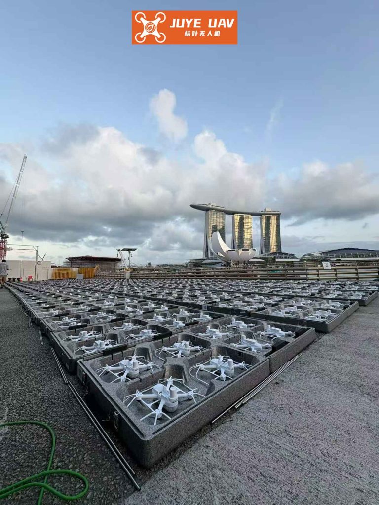
The figure above conceptually illustrates the kind of tightly coordinated drone formation that our control framework aims to enable, showcasing the potential for complex, synchronized flight patterns.
2. Q-Learning Based Path Planning for the Virtual Leader
To navigate the unknown 3D environment, we employ a model-free Reinforcement Learning (RL) technique, Q-Learning, to plan a path for the virtual leader. This algorithm allows the leader to learn an optimal policy through interaction with the environment without requiring a prior model.
2.1 State and Action Space Discretization
The continuous 3D workspace is discretized into a grid of size $n_x \times n_y \times n_z$. Each grid cell represents a discrete state $s$ of the virtual leader. The set of all states is $\mathcal{S} = \{s_1, s_2, …, s_{n_x \cdot n_y \cdot n_z}\}$. The action space is designed to allow movement to neighboring cells in 26 possible directions (the centers of the 6 faces, 12 edges, and 8 vertices of a cube centered on the current cell). The action set is $\mathcal{A} = \{a_1, a_2, …, a_{26}\}$. The step length $d$ associated with an action depends on the direction: $d=1$ for face moves, $d=\sqrt{2}$ for edge moves, and $d=\sqrt{3}$ for vertex moves. This fine discretization facilitates smooth path generation.
2.2 Reward Function Design
A well-designed reward function guides the learning process. The immediate reward $r$ for taking action $a$ in state $s$, leading to state $s’$, is composed of an action penalty and a state-based reward:
$$ r = r_{\text{act}}(d) + r_{\text{env}}(s’, P_g, \Lambda_o) $$
where:
- $r_{\text{act}}(d)$ penalizes longer steps to encourage finding shorter paths: $r_{\text{act}}(d) = -d$.
- $r_{\text{env}}(s’, P_g, \Lambda_o)$ evaluates the next state:
$$
r_{\text{env}} =
\begin{cases}
+100, & \text{if } s’ = P_g \text{ (target)} \\
-50, & \text{if } s’ \in \Lambda_o \text{ (obstacle) or } s’ \text{ is out of bounds} \\
0, & \text{otherwise}
\end{cases}
$$
2.3 Policy and Q-Table Update
The leader uses an $\epsilon$-greedy policy to balance exploration and exploitation:
$$
\pi(s) =
\begin{cases}
\text{a random action from } \mathcal{A}, & \text{with probability } \epsilon \\
\arg\max_{a \in \mathcal{A}} Q(s, a), & \text{with probability } 1-\epsilon
\end{cases}
$$
The Q-table is initialized to zero and updated after each action using the standard Q-Learning rule:
$$ Q(s, a) \leftarrow Q(s, a) + \alpha \left[ r + \gamma \max_{a’ \in \mathcal{A}} Q(s’, a’) – Q(s, a) \right] $$
where $\alpha \in (0, 1]$ is the learning rate and $\gamma \in [0, 1)$ is the discount factor.
2.4 Path Smoothing with B-Spline
The Q-Learning algorithm produces a sequence of discrete waypoints $\{\boldsymbol{P}_0^m\}, m=0,…,M$. To generate a smooth, continuous trajectory suitable for the drone formation to follow, we fit a B-spline curve to these waypoints. A B-spline curve of degree $l$ is defined as:
$$ \boldsymbol{P}_0(t) = \sum_{m=0}^{M} \boldsymbol{P}_0^m \cdot \mathfrak{R}_{m, l}(t) $$
where $\mathfrak{R}_{m, l}(t)$ are the B-spline basis functions, calculated recursively via the de Boor-Cox algorithm. This results in a $C^{l-1}$ continuous trajectory $\boldsymbol{P}_0(t)$ for the virtual leader.
The table below summarizes the key parameters for the Q-Learning path planner.
| Parameter | Description | Value |
|---|---|---|
| $\alpha$ | Learning Rate | 0.1 |
| $\gamma$ | Discount Factor | 0.8 |
| $\epsilon$ | Exploration Rate | 0.1 |
| $(n_x, n_y, n_z)$ | Grid Dimensions | (30, 40, 15) |
| $N_{\text{episodes}}$ | Training Episodes | $6 \times 10^5$ |
| $l$ | B-spline Degree | 3 |
3. Distributed Cooperative Controller Design
The controller for the follower drones is designed in a hierarchical structure: an outer-loop position controller and an inner-loop attitude controller. The overall control architecture integrates formation tracking, collision/obstacle avoidance via artificial potential fields, and disturbance rejection via an Extended State Observer (ESO).
3.1 Position Control Loop with Artificial Potential Field
The desired trajectory for follower $i$ is $\boldsymbol{P}^d_i = \boldsymbol{P}_0 – \boldsymbol{\Delta}_{i0}$. Define the position and velocity tracking errors as $\tilde{\boldsymbol{P}}_i = \boldsymbol{P}_i – \boldsymbol{P}^d_i$ and $\tilde{\boldsymbol{V}}_i = \boldsymbol{V}_i – \dot{\boldsymbol{P}}^d_i$.
We propose the following distributed virtual control law $\boldsymbol{U}^P_i$ for the position loop:
$$
\boldsymbol{U}^P_i = -\sum_{j \in \mathcal{N}_i} a_{ij}\left[ \boldsymbol{\Gamma}_{1i} (\tilde{\boldsymbol{P}}_i – \tilde{\boldsymbol{P}}_j) + \boldsymbol{\Gamma}_{2i} (\tilde{\boldsymbol{V}}_i – \tilde{\boldsymbol{V}}_j) \right] – a_{i0}\left( \boldsymbol{\Gamma}_{1i} \tilde{\boldsymbol{P}}_i + \boldsymbol{\Gamma}_{2i} \tilde{\boldsymbol{V}}_i \right) + \boldsymbol{F}_i
$$
where $\boldsymbol{\Gamma}_{1i} = \boldsymbol{\Gamma}_{1i}^T > 0$ and $\boldsymbol{\Gamma}_{2i} = \boldsymbol{\Gamma}_{2i}^T > 0$ are controller gain matrices. The term $\boldsymbol{F}_i = [F_{xi}, F_{yi}, F_{zi}]^T$ is the repulsive force derived from a novel artificial potential field to ensure collision and obstacle avoidance within the drone formation.
Artificial Potential Field Design: The repulsive force acts when the distance between agent $i$ and an obstacle (or another drone) is less than a perception range $R^p$ but greater than the safety distance $R_s$. We define the set of perceived obstacles for drone $i$ as:
$$ \mathcal{N}^o_i = \{ j \mid \|\boldsymbol{P}_i – \boldsymbol{P}_j\| \le R^p_u, j \in \mathcal{N}_i \} \cup \{ k \mid \text{dist}(\boldsymbol{P}_i, \text{Obstacle}_k) \le R^p_o, k=1,…,M \} $$
where $R^p_u$ and $R^p_o$ are the perception ranges for drones and static obstacles, respectively, with $R^p > R_s$. The repulsive force component along the line connecting drone $i$ to entity $c \in \mathcal{N}^o_i$ is:
$$ F_{i,c} =
\begin{cases}
-\kappa_{ci} \left( \dfrac{1}{R_{i,c} – R_s} – \dfrac{1}{R^p} \right) \dfrac{1}{(R_{i,c} – R_s)^2}, & R_s < R_{i,c} < R^p \\
0, & R_{i,c} \ge R^p
\end{cases}
$$
where $R_{i,c} = \|\boldsymbol{P}_i – \boldsymbol{P}_c\|$, $\kappa_{ci}>0$ is a repulsive gain, and $R^p$ is the relevant perception range ($R^p_u$ or $R^p_o$). The total repulsive force $\boldsymbol{F}_i$ is the vector sum of all such components from entities in $\mathcal{N}^o_i$.
From the virtual control $\boldsymbol{U}^P_i = [u_{xi}, u_{yi}, u_{zi}]^T$, the desired total thrust $T_i$ and desired roll/pitch angles ($\phi^d_i, \theta^d_i$) can be computed, assuming a desired yaw angle $\psi^d_i$ is given:
$$
\begin{aligned}
T_i &= m \sqrt{u_{xi}^2 + u_{yi}^2 + (u_{zi} + g)^2} \\
\phi^d_i &= \arcsin\left( \frac{m}{T_i} (u_{xi} \sin\psi^d_i – u_{yi} \cos\psi^d_i) \right) \\
\theta^d_i &= \arctan\left( \frac{u_{xi} \cos\psi^d_i + u_{yi} \sin\psi^d_i}{u_{zi} + g} \right)
\end{aligned}
$$
Thus, the attitude loop is commanded to track $\boldsymbol{\Theta}^d_i = [\phi^d_i, \theta^d_i, \psi^d_i]^T$.
3.2 Attitude Control Loop with Extended State Observer (ESO)
Define the attitude tracking error $\boldsymbol{E}_{\Theta i} = \boldsymbol{\Theta}_i – \boldsymbol{\Theta}^d_i$. Using the backstepping technique, we introduce a virtual control $\boldsymbol{\Omega}^d_i$ for the angular velocity:
$$ \boldsymbol{\Omega}^d_i = \dot{\boldsymbol{\Theta}}^d_i – \boldsymbol{K}_{\Theta i} \boldsymbol{E}_{\Theta i} $$
where $\boldsymbol{K}_{\Theta i} = \boldsymbol{K}_{\Theta i}^T > 0$. The angular velocity error is $\boldsymbol{E}_{\Omega i} = \boldsymbol{\Omega}_i – \boldsymbol{\Omega}^d_i$.
To handle the lumped disturbance $\boldsymbol{D}_i(t)$, we design a linear ESO. Let $\hat{\boldsymbol{\Omega}}_i$ and $\hat{\boldsymbol{D}}_i$ be the estimates of $\boldsymbol{\Omega}_i$ and $\boldsymbol{D}_i$, respectively. The ESO is constructed as:
$$
\begin{cases}
\dot{\hat{\boldsymbol{\Omega}}}_i = \boldsymbol{F}(\boldsymbol{\Theta}_i, \boldsymbol{\Omega}_i) + \boldsymbol{G} \boldsymbol{U}^\Theta_i + \hat{\boldsymbol{D}}_i – \boldsymbol{\beta}_{1i} (\hat{\boldsymbol{\Omega}}_i – \boldsymbol{\Omega}_i) \\
\dot{\hat{\boldsymbol{D}}}_i = – \boldsymbol{\beta}_{2i} (\hat{\boldsymbol{\Omega}}_i – \boldsymbol{\Omega}_i)
\end{cases}
$$
where $\boldsymbol{\beta}_{1i}$ and $\boldsymbol{\beta}_{2i}$ are positive definite observer gain matrices. The estimation errors are $\tilde{\boldsymbol{\Omega}}_i = \hat{\boldsymbol{\Omega}}_i – \boldsymbol{\Omega}_i$ and $\tilde{\boldsymbol{D}}_i = \hat{\boldsymbol{D}}_i – \boldsymbol{D}_i$.
Finally, the actual moment control input $\boldsymbol{U}^\Theta_i$ for the attitude dynamics is designed as:
$$ \boldsymbol{U}^\Theta_i = \boldsymbol{G}^{-1} \left( -\boldsymbol{K}_{\Omega i} \boldsymbol{E}_{\Omega i} – \boldsymbol{E}_{\Theta i} – \boldsymbol{F}(\boldsymbol{\Theta}_i, \boldsymbol{\Omega}_i) – \hat{\boldsymbol{D}}_i + \dot{\boldsymbol{\Omega}}^d_i \right) $$
where $\boldsymbol{K}_{\Omega i} = \boldsymbol{K}_{\Omega i}^T > 0$ is a controller gain matrix. This control law actively compensates for the estimated disturbance $\hat{\boldsymbol{D}}_i$, enhancing the robustness of each agent in the drone formation.
3.3 Stability Analysis
The stability of the overall closed-loop drone formation system can be established using Lyapunov theory. Consider a composite Lyapunov function candidate:
$$ L = L_P + L_\Theta $$
where $L_P$ is for the position loop and $L_\Theta$ for the attitude loop.
Position Subsystem: Using the properties of the Laplacian matrix and the fact that the repulsive potential field is positive definite and its gradient yields $-\boldsymbol{F}_i$, it can be shown that the derivative of $L_P$ satisfies:
$$ \dot{L}_P \leq -\tilde{\boldsymbol{V}}^T [ (\mathcal{L}+\mathcal{B}) \otimes \boldsymbol{\Gamma}_2 ] \tilde{\boldsymbol{V}} \leq 0 $$
where $\tilde{\boldsymbol{V}} = [\tilde{\boldsymbol{V}}_1^T, …, \tilde{\boldsymbol{V}}_N^T]^T$. By LaSalle’s invariance principle, the position tracking errors converge to zero, i.e., $\tilde{\boldsymbol{P}}_i, \tilde{\boldsymbol{V}}_i \to \mathbf{0}$.
Attitude Subsystem: The Lyapunov function for the attitude loop includes the tracking errors and the ESO estimation errors:
$$ L_\Theta = \frac{1}{2} \sum_{i=1}^N \left( \boldsymbol{E}_{\Theta i}^T \boldsymbol{E}_{\Theta i} + \boldsymbol{E}_{\Omega i}^T \boldsymbol{E}_{\Omega i} + \boldsymbol{\xi}_i^T \boldsymbol{P}_i \boldsymbol{\xi}_i \right) $$
where $\boldsymbol{\xi}_i = [\tilde{\boldsymbol{\Omega}}_i^T, \tilde{\boldsymbol{D}}_i^T]^T$ and $\boldsymbol{P}_i$ is a positive definite matrix satisfying a Lyapunov equation for the ESO error dynamics. Taking the derivative and substituting the control law and ESO dynamics yields:
$$ \dot{L}_\Theta \leq \sum_{i=1}^N \left( -\boldsymbol{E}_{\Theta i}^T \boldsymbol{K}_{\Theta i} \boldsymbol{E}_{\Theta i} – \boldsymbol{E}_{\Omega i}^T (\boldsymbol{K}_{\Omega i} – \frac{1}{2}\boldsymbol{I}) \boldsymbol{E}_{\Omega i} – \lambda_{\min}(\boldsymbol{Q}_i) \|\boldsymbol{\xi}_i\|^2 + \eta_i \right) $$
where $\eta_i$ is a positive constant related to the bound of $\dot{\boldsymbol{D}}_i(t)$. By appropriately selecting gains $\boldsymbol{K}_{\Theta i}, \boldsymbol{K}_{\Omega i}, \boldsymbol{\beta}_{1i}, \boldsymbol{\beta}_{2i}$, we can ensure $\dot{L}_\Theta \leq 0$ outside a small neighborhood of the origin. This proves that all signals in the attitude loop are uniformly ultimately bounded. Consequently, the entire drone formation control system is stable, with tracking errors converging to a small residual set around zero.
4. Simulation Results and Analysis
To validate the proposed integrated framework for the drone formation, numerical simulations were conducted in MATLAB. The scenario involves a virtual leader and N=3 follower quadrotors. The environment contains three cylindrical obstacles. The desired formation is a vertical triangular pattern with offsets $\boldsymbol{\Delta}_{10}=[-2,0,0]^T$, $\boldsymbol{\Delta}_{20}=[0,-2,0]^T$, $\boldsymbol{\Delta}_{30}=[0,0,-1]^T$ m. The communication graph is undirected and connected.
The physical parameters of the quadrotors and the key controller gains are listed in the following tables.
| Parameter | Symbol | Value |
|---|---|---|
| Mass | $m$ | 1.3 kg |
| Moment of Inertia (X) | $J_x$ | 6.23e-3 kg·m² |
| Moment of Inertia (Y) | $J_y$ | 6.23e-3 kg·m² |
| Moment of Inertia (Z) | $J_z$ | 1.12e-3 kg·m² |
| Gain Matrix | Value (diagonal) |
|---|---|
| $\boldsymbol{\Gamma}_{1i}$, $\boldsymbol{\Gamma}_{2i}$ | $\text{diag}(5,5,5)$, $\text{diag}(1,1,1)$ |
| $\boldsymbol{K}_{\Theta i}$, $\boldsymbol{K}_{\Omega i}$ | $\text{diag}(100,100,100)$, $\text{diag}(5,5,5)$ |
| $\boldsymbol{\beta}_{1i}$, $\boldsymbol{\beta}_{2i}$ | $\text{diag}(10,10,10)$, $\text{diag}(100,100,100)$ |
| Repulsive Gain $\kappa_{ci}$ | 0.7 |
| Safety/Perception Radii $R_s$, $R^p$ | 0.5 m, 3.0 m |
4.1 Leader Path Planning Result
The Q-Learning algorithm successfully planned a path for the virtual leader from the start point (5,5,4)m to the goal (30,38,11)m. The learning process showed convergence in the total reward per episode. The discrete waypoints were then smoothed using a cubic B-spline, producing a continuous, differentiable, and obstacle-free trajectory $\boldsymbol{P}_0(t)$ for the drone formation to follow.
4.2 Formation Flight and Obstacle Avoidance
The proposed distributed controller was applied to the three follower drones. The following key results demonstrate the performance of the drone formation:
- Trajectory Tracking: All follower drones accurately tracked their desired trajectories $\boldsymbol{P}^d_i(t)$, which were offset from the leader’s planned path. The position tracking errors converged to near zero.
- Formation Keeping & Shape Deformation: In open space, the followers maintained the predefined triangular formation precisely. When approaching obstacles, the artificial potential field $\boldsymbol{F}_i$ actively induced controlled repulsive forces. This caused a temporary, elastic deformation of the drone formation shape to navigate around obstacles, as seen in the simulation plots. After passing the obstacle, the formation seamlessly reverted to its original geometry.
- Collision Avoidance: The minimum distances between any two drones and between drones and obstacles remained strictly greater than the safety distance $R_s = 0.5$ m throughout the simulation, confirming effective collision and obstacle avoidance.
4.3 Disturbance Rejection Performance
To test robustness, significant lumped disturbances $\boldsymbol{D}_i(t)$ were injected into the attitude dynamics of each follower, combining constant biases, sinusoidal terms, and time-varying components related to the control input. The ESO demonstrated excellent estimation performance, with $\hat{\boldsymbol{D}}_i(t)$ rapidly converging to closely match the true disturbance $\boldsymbol{D}_i(t)$. Consequently, the attitude tracking errors $\boldsymbol{E}_{\Theta i}$ and $\boldsymbol{E}_{\Omega i}$ remained small and bounded despite the disturbances, showcasing the strong disturbance rejection capability of the proposed control scheme for the drone formation.
4.4 Comparative Analysis
For comparison, a simplified controller treating drones as point masses (3-DOF) was also simulated. While it achieved tracking, it could not account for attitude dynamics or disturbances. Another comparison with a backstepping controller without the ESO showed noticeably larger attitude tracking oscillations in the presence of disturbances. These comparisons highlight the advantages of our full 6-DOF, disturbance-observer-based design for realistic drone formation control.
5. Conclusion
This article presented a comprehensive solution for the safe navigation of a quadrotor drone formation in an unknown 3D environment. The solution integrates a reinforcement learning-based path planner and a distributed robust cooperative controller. The virtual leader’s path is generated using Q-Learning combined with B-spline smoothing, ensuring a smooth, obstacle-free trajectory without prior environmental maps. For the follower drones, a distributed control protocol was designed using backstepping and consensus theory. It explicitly addresses the full 6-DOF nonlinear dynamics, incorporates a novel artificial potential field for simultaneous trajectory tracking and collision/obstacle avoidance, and employs an Extended State Observer for active disturbance rejection. Lyapunov-based stability analysis proves the uniform ultimate boundedness of all tracking errors. Extensive simulations confirm that the drone formation can successfully learn a path, follow it while maintaining formation, avoid static obstacles and inter-agent collisions, and remain robust against significant disturbances. Future work will focus on extending the framework to dynamic environments with moving obstacles, considering communication delays and bandwidth constraints within the drone formation, and implementing the algorithms on hardware platforms for real-world validation.