
In modern communication systems, the medium-long wave band remains critically important for long-distance and beyond-line-of-sight transmissions due to its superior propagation stability and penetration capability. However, conventional antenna architectures deployed for this frequency range, such as fixed tower structures and ground-based mast systems, suffer from inherent limitations including poor mobility, lengthy deployment cycles, and vulnerability to physical attacks. These constraints motivate the exploration of alternative platforms that can combine rapid deployability with robust electromagnetic performance. In our work, we investigate a novel configuration that leverages drone technology to suspend a flexible radiating element, thereby achieving a highly mobile and quickly deployable medium-long wave communication system. The core challenge we address is the characterization of wind-induced deformation and its subsequent impact on the antenna radiation properties, which is essential for ensuring reliable operation under realistic environmental conditions.
The integration of drone technology with flexible antenna design opens up new possibilities for tactical communication scenarios where infrastructure is unavailable or compromised. Unlike traditional fixed installations that require extensive ground preparation and permanent structures, a drone-mounted flexible antenna can be deployed within minutes, repositioned dynamically, and retrieved when necessary. This operational flexibility, however, introduces complex structural dynamics because the radiating element is susceptible to aerodynamic loads. The wind forces acting on the slender conductor cause it to deviate from its intended vertical orientation, leading to changes in current distribution, input impedance, and radiation pattern. Understanding these effects is essential for predicting the communication performance under various wind conditions and for developing compensation strategies that maintain link quality.
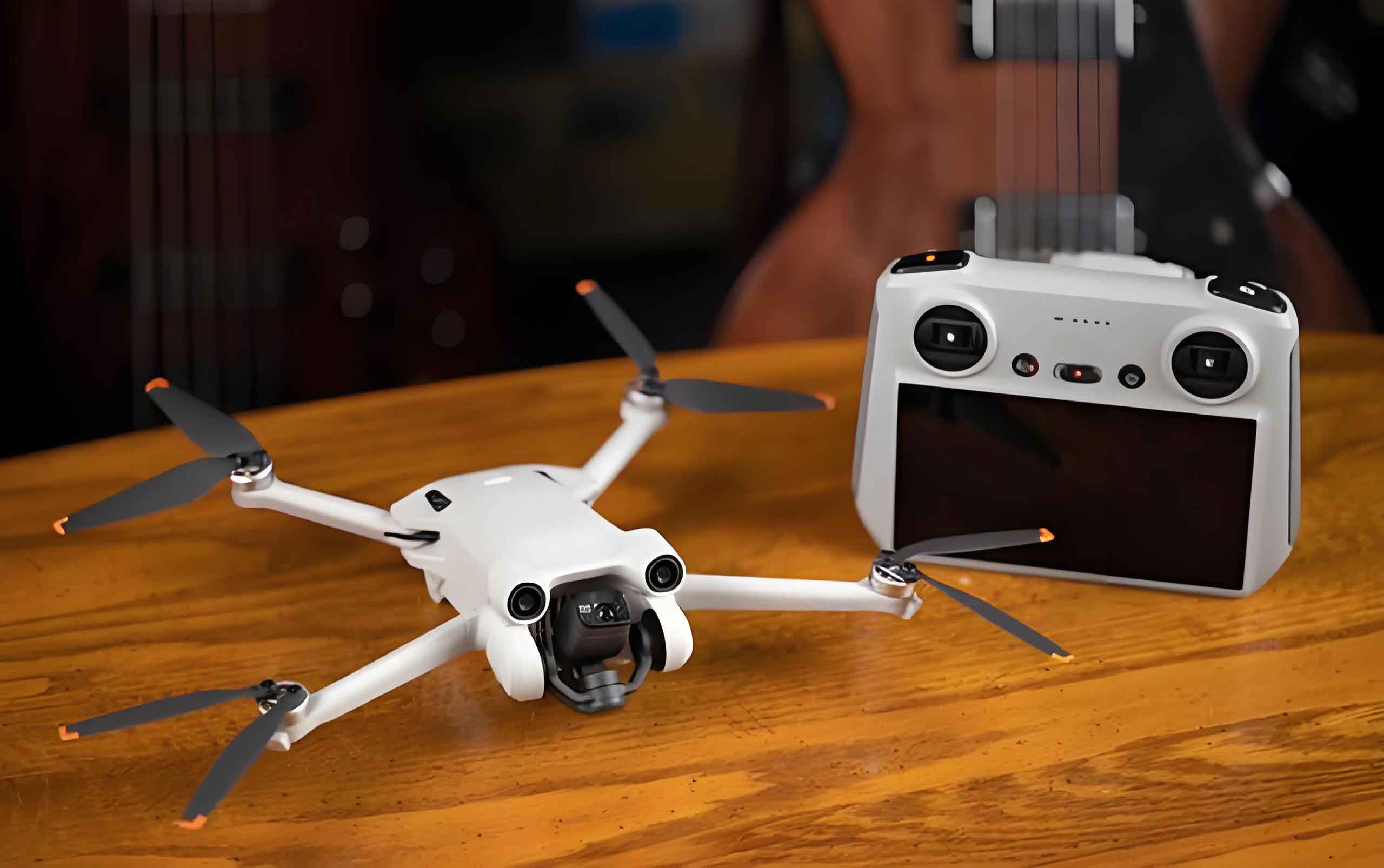
Our proposed system consists of three primary components: the unmanned aerial vehicle platform that provides stable hovering and load-bearing support, the bottom-fed equipment pod that houses the transmitter and power amplifier, and the flexible radiating element itself. The antenna is constructed from a copper conductor with a diameter of 2 mm and an electrical conductivity of 5.8×10⁷ S/m, reinforced with tensile fibers to withstand the mechanical stresses during deployment and operation. The equipment pod serves a dual purpose: it contains the feeding electronics and acts as a gravitational stabilizer that tensions the antenna, helping to maintain its straightness under mild conditions. The pod is electrically grounded to approximate an ideal ground plane, and its non-metallic housing ensures negligible electromagnetic interference with the radiation characteristics. This configuration allows the antenna to be conveniently stowed during transport and rapidly deployed when needed, making full use of the agility offered by modern drone technology.
To establish a theoretical foundation for our analysis, we treat the vertically suspended flexible antenna as a lossy transmission line of length L, characteristic impedance Z₀, and complex propagation constant γ = α + jβ, where α represents the attenuation constant accounting for ohmic and radiation losses, and β = 2π/λ is the phase constant. The input impedance Zin of such a structure is expressed as:
$$
Z_{in}=Z_{0}\frac{Z_{L}+Z_{0}\tanh(\gamma L)}{Z_{0}+Z_{L}\tanh(\gamma L)}
$$
For the case of an open-circuited antenna where ZL → ∞, this expression simplifies to:
$$
Z_{in}=\frac{Z_{0}}{\tanh(\gamma L)}
$$
The current distribution along the antenna, which directly determines the radiation characteristics, follows a sinusoidal profile modified by the finite length of the structure. We express the current at a position z along the antenna as:
$$
I(z)=\frac{I_{0}}{\sin(kh)}\sin\left[k(h-z)\right]
$$
where I₀ is the input current at the feed point, h is the physical height of the antenna, and k = 2π/λ is the free-space wavenumber. The effective height he, which is a key figure of merit relating the antenna physical dimensions to its radiation capability, is defined as:
$$
h_{e}=\frac{1}{I_{0}}\int_{0}^{h}I(z)\,dz=\frac{1-\cos(kh)}{k\sin(kh)}=\frac{1}{k}\tan\left(\frac{kh}{2}\right)
$$
For electrically short antennas where kh ≪ 1, the small-angle approximation yields he ≈ h/2, indicating that the effective height is approximately half the physical height. The radiation resistance Rr, which quantifies the power radiated into free space for a given input current, is directly related to the effective height through:
$$
R_{r}=240\pi^{2}\left(\frac{h_{e}}{\lambda}\right)^{2}
$$
Substituting the approximation for he gives:
$$
R_{r}=240\pi^{2}\left(\frac{h}{2\lambda}\right)^{2}=10\pi^{2}\left(\frac{h}{\lambda}\right)^{2}
$$
This relationship highlights that the radiation resistance scales quadratically with the physical height, making taller antennas more efficient radiators. The overall radiation efficiency η is then obtained from the ratio of radiation resistance to total input resistance:
$$
\eta=\frac{P_{r}}{P_{in}}=\frac{R_{r}}{R_{r}+R_{L}}
$$
where RL represents the loss resistance associated with conductor ohmic losses and ground losses. These theoretical expressions provide the foundation for predicting the performance of our flexible antenna system, although they are derived under idealized assumptions of a perfectly conducting ground plane and a straight vertical conductor. In practice, the wind-induced deformation modifies the effective height and current distribution, leading to deviations from these ideal values.
We conducted a series of electromagnetic simulations using the Method of Moments implemented in the FEKO software package to evaluate the antenna performance as a function of its electrical length. The operating frequency was set to 200 kHz, which lies within the medium-long wave band and is suitable for the suspended heights achievable with current drone technology. We simulated antennas with electrical lengths ranging from λ/20 to 3λ/4 to understand the transition from electrically short to electrically long behavior. The far-field radiation patterns and current distributions obtained from these simulations revealed a critical threshold: when the electrical length exceeds 0.5λ, reverse currents appear on the antenna, causing the main lobe to split and significantly degrading the overall radiation performance. This finding establishes an upper bound on the antenna length for omnidirectional communication applications.
Based on this constraint, we selected a physical antenna length of 350 m for detailed investigation, which corresponds to an electrical length of approximately 0.23λ at 200 kHz. This length balances the need for adequate radiation efficiency with the practical limitations of drone technology payload capacity and deployment logistics. We also reserved a 10 m length margin to allow for fine-tuning of the effective suspended height during operation. The input impedance characteristics were analyzed across a range of lengths from 250 m to 375 m, and we observed that shorter antennas exhibit more gradual impedance variations and larger capacitive reactance, while longer antennas show increased input resistance. The reflection coefficient curves for five closely spaced lengths around the selected value confirmed that the 350 m configuration achieves the best impedance matching at the operating frequency, with the minimum return loss.
To quantify the influence of wind-induced deformation on the antenna performance, we developed a nonlinear dynamic model based on the catenary theory and the method of infinitesimal elements. The model captures the equilibrium of forces acting on each differential segment of the antenna, including tension, gravity, and aerodynamic drag. We established two coordinate systems: an inertial frame with its origin at the ground anchor point and the Zg axis pointing vertically upward, and a body-fixed frame that follows the local orientation of the antenna, with unit vectors along the tangential, normal, and binormal directions. For a differential element ds at position s along the antenna, the dynamic equation derived from Newton second law is:
$$
\frac{\partial \mathbf{T}}{\partial s}+\rho_{l}\mathbf{g}+\mathbf{f}_{a}=\rho_{l}\frac{\partial^{2}\mathbf{R}}{\partial t^{2}}
$$
where T = T(s)τ̂ is the tension vector, ρl is the linear mass density of the antenna, g = −g k̂ is the gravitational acceleration, fa is the aerodynamic force per unit length, and R(s,t) is the position vector. For steady-state conditions where the time-varying inertial term vanishes, the equation simplifies to:
$$
\frac{d\mathbf{T}}{ds}+\rho_{l}\mathbf{g}+\mathbf{f}_{a}=0
$$
The aerodynamic force is modeled using the Morrison equation, with the tangential component neglected and only the normal component considered, which is the dominant contribution for slender cylindrical structures:
$$
\mathbf{f}_{a}=-\frac{1}{2}\rho_{a}C_{D}D|\mathbf{V}_{n}|\mathbf{V}_{n}
$$
where ρa is the air density, CD is the normal drag coefficient, D is the antenna diameter, and Vn = Vw − (Vw·τ̂)τ̂ is the component of the wind velocity vector Vw perpendicular to the antenna axis. To facilitate numerical solution, we non-dimensionalize the governing equation using the following scaling:
$$
\boldsymbol{\xi}=\frac{s}{L},\quad \mathbf{t}=\frac{\mathbf{T}}{\rho_{l}gL},\quad \mathbf{v}=\frac{\mathbf{V}_{w}}{V_{ref}}
$$
where L is the total antenna length and Vref is a reference wind speed. Substituting these dimensionless variables into the steady-state equation yields:
$$
\frac{d\mathbf{t}}{d\boldsymbol{\xi}}+\hat{\mathbf{k}}+\frac{1}{2}\alpha|\mathbf{v}_{n}|\mathbf{v}_{n}=0
$$
The dimensionless aerodynamic parameter α emerges as:
$$
\alpha=\frac{\rho_{a}C_{D}DLV_{ref}^{2}}{\rho_{l}gL}
$$
which physically represents the ratio of aerodynamic forces to gravitational forces. When α is large, wind effects dominate the antenna shape, while small α indicates that gravity maintains the antenna in a near-vertical orientation. The boundary conditions for this equation are fixed at both ends: the ground anchor point at ξ = 0 is stationary, and the drone attachment point at ξ = 1 is constrained by the hovering altitude h of the unmanned aerial vehicle.
We solved the nonlinear boundary value problem using the shooting method, iteratively adjusting the initial conditions until the boundary conditions at both ends were satisfied within a specified tolerance. The solution yielded the equilibrium shape r(ξ) and tension distribution t(ξ) for each wind condition. To characterize the wind environment, we adopted the power-law profile to describe the variation of wind speed with height, which is a standard approach in atmospheric boundary layer modeling. Three representative wind conditions were selected based on the Beaufort scale: light wind at 3 m/s (Beaufort force 2), moderate wind at 7 m/s (Beaufort force 4), and strong wind at 12 m/s (Beaufort force 6). These conditions span the range from calm operational scenarios to the upper limit of practical drone technology stability.
The numerical solutions produced parametric equations describing the antenna shape under each wind condition. For the light wind case, the horizontal displacement u(ξ) and vertical height v(ξ) are given by:
$$
u(\xi)=17.5\times\xi\times(1-\xi^{2})
$$
$$
v(\xi)=L\times(\xi-0.35\times\xi^{2})
$$
For the moderate wind case:
$$
u(\xi)=52.5\times\xi\times(1-\xi^{1.5})
$$
$$
v(\xi)=L\times(\xi-1.75\times\xi^{2})
$$
For the strong wind case:
$$
u(\xi)=105\times\xi\times(1-\xi^{1.2})
$$
$$
v(\xi)=L\times(\xi-4.2\times\xi^{2})
$$
These expressions reveal a progressive increase in horizontal deflection as the wind speed intensifies. In the light wind scenario, the antenna remains nearly vertical with a maximum horizontal displacement of only 2.6 m, representing 0.74% of the total length. Under moderate winds, the displacement increases to 9.8 m (2.8%), and in strong winds, it reaches 27.1 m (7.74%). The drone hovering altitude adjusts accordingly, decreasing from 349 m in light winds to 345 m in strong winds, as shown in the following table summarizing the key shape parameters.
| Wind Condition | Maximum Horizontal Displacement (m) | Relative Horizontal Displacement (%) | Drone Hovering Altitude (m) |
|---|---|---|---|
| Light Wind (3 m/s) | 2.6 | 0.74 | 349 |
| Moderate Wind (7 m/s) | 9.8 | 2.80 | 348 |
| Strong Wind (12 m/s) | 27.1 | 7.74 | 345 |
The moderate horizontal displacements observed even under strong wind conditions indicate that the antenna system maintains structural stability within the operational envelope of typical drone technology. The gravitational tension provided by the equipment pod, combined with the inherent stiffness of the copper conductor, prevents large-amplitude swinging or whipping motions that would otherwise render the antenna unusable. This stability is crucial for maintaining consistent electromagnetic performance, as excessive deformation would alter the current distribution and potentially degrade the radiation pattern.
With the deformed antenna shapes obtained from the dynamic analysis, we proceeded to evaluate the electromagnetic performance by importing the shape data into FEKO for full-wave simulation. The three wind conditions produced six radiation patterns each, with the E-plane and H-plane patterns analyzed separately to assess the directional characteristics. The E-plane radiation patterns, which show the radiation intensity in the vertical plane containing the antenna axis, remained well-behaved across all wind conditions. The main lobe structure was preserved without splitting or significant distortion, and the side lobe levels did not exhibit abnormal elevation. This stability in the E-plane pattern is attributed to the relatively small angular deviation of the antenna from the vertical, which does not fundamentally alter the current distribution responsible for the vertical polarization radiation.
The H-plane radiation patterns, which represent the horizontal coverage, are particularly important for omnidirectional communication links. Our simulations revealed that the H-plane patterns remained approximately circular across all wind conditions, with only minor variations in the radial coordinate. This indicates that the antenna preserves its omnidirectional radiation characteristic even under significant wind loading. The slight asymmetry introduced by the wind-induced curvature is not sufficient to create nulls or deep fades in any particular azimuthal direction, ensuring that the communication link remains available regardless of the relative orientation between the transmitter and receiver.
The quantitative performance metrics extracted from the simulations further confirm the robustness of the proposed system. The voltage standing wave ratio, which quantifies the impedance matching quality, remained within the range of 1.79 to 1.82 across the three wind conditions, indicating good matching with the transmitter output. The radiation efficiency, defined as the ratio of radiated power to the input power, exceeded 90% in all cases, demonstrating that the ohmic losses in the conductor and the ground losses are well controlled. The maximum gain, which combines the radiation efficiency with the directivity, showed a variation of less than 0.02 dBi across the entire wind speed range, from 4.74 dBi in light winds to 4.72 dBi in strong winds. These performance parameters are summarized in the following table.
| Wind Condition | Voltage Standing Wave Ratio | Radiation Efficiency (%) | Maximum Gain (dBi) |
|---|---|---|---|
| Light Wind (3 m/s) | 1.79 | 90.79 | 4.74 |
| Moderate Wind (7 m/s) | 1.81 | 90.74 | 4.73 |
| Strong Wind (12 m/s) | 1.82 | 90.61 | 4.72 |
The minimal degradation in performance metrics as wind speed increases from 3 m/s to 12 m/s is a compelling demonstration of the system resilience. The voltage standing wave ratio increases by only 1.7%, the radiation efficiency decreases by 0.2 percentage points, and the maximum gain drops by a mere 0.02 dBi. These changes are well within the acceptable margins for practical communication systems, indicating that the wind-induced deformation does not compromise the antenna ability to establish and maintain reliable links. The physical mechanism behind this robustness lies in the fact that the current distribution, although perturbed by the geometric deformation, retains its fundamental sinusoidal character with the same dominant wavelength. The effective height, which governs the radiation resistance and pattern shape, changes only slightly because the projection of the antenna onto the vertical direction remains close to the physical length.
To further explore the relationship between antenna length and performance, we conducted a parametric sweep of five lengths centered around the selected 350 m design. The reflection coefficient curves for lengths of 340, 345, 350, 355, and 360 m showed that the 345 m antenna achieved the lowest return loss at 200 kHz, suggesting that slight adjustments to the deployed length could optimize the impedance match for specific operating conditions. This flexibility is a practical advantage of the drone technology platform, as the hovering altitude can be adjusted in real-time to fine-tune the antenna electrical length. The 10 m length margin we incorporated into the design provides the necessary range for this optimization, allowing the system to adapt to changing frequency assignments or environmental conditions.
The dynamic response of the antenna system to wind gusts and turbulence, while not the primary focus of this steady-state analysis, deserves consideration for comprehensive system design. The nonlinear dynamic model we developed can be extended to include time-varying wind inputs, enabling the prediction of transient oscillations and the assessment of stability margins. The natural frequencies of the suspended antenna, which depend on the tension distribution and the mass per unit length, determine the susceptibility to resonant excitation by periodic wind loads. For the 350 m antenna with the equipment pod providing gravitational tension, the fundamental natural frequency is expected to be well below the typical gust frequencies, implying that the system responds quasi-statically to wind variations rather than exhibiting resonant amplification. This further supports the conclusion that the steady-state analysis captures the dominant behavior relevant for communication performance.
In practical deployment scenarios, the drone platform must maintain its position against the wind forces transmitted through the antenna tether. The horizontal component of the tension at the attachment point increases with wind speed, requiring the drone flight controller to allocate thrust accordingly. Modern drone technology with GPS-based position holding and inertial navigation systems can compensate for these forces up to certain limits, beyond which the platform may drift from its intended location. The maximum horizontal force expected under the 12 m/s wind condition, calculated from the tension distribution obtained from our dynamic model, is within the thrust capability of medium-lift unmanned aerial vehicles designed for industrial and tactical applications. This compatibility between the antenna requirements and the platform capabilities is essential for the practical realization of the proposed system.
The ground anchor point and the equipment pod also play critical roles in the overall system performance. The anchor must provide a stable electrical ground connection and withstand the tension forces transmitted through the antenna. In field deployments, a portable ground stake or a weighted base plate can serve this purpose, with the additional benefit of being quickly installed and removed. The equipment pod, which houses the transmitter and impedance matching network, must be designed to withstand the mechanical stresses of deployment, operation, and retrieval. Its gravitational mass contributes to the antenna tension, and its electrical grounding ensures the proper reference for the antenna input impedance. We designed the pod with a streamlined shape to minimize additional aerodynamic drag, which would otherwise increase the horizontal force on the antenna and exacerbate the wind-induced deformation.
The choice of the operating frequency and antenna length is influenced by the practical constraints of drone technology payload capacity and the physical dimensions of the stowed antenna. A 350 m conductor, when coiled or folded for transport, requires a volume that is compatible with the cargo capacity of medium-lift drones. The deployment mechanism, which releases the antenna from the drone as it ascends to the operational altitude, must ensure smooth unreeling without tangling or kinking. The retrieval process reverses this sequence, winding the antenna back onto the spool as the drone descends. These mechanical design considerations, while not the focus of our electromagnetic analysis, are integral to the overall feasibility of the system and represent areas where further development of drone technology can enhance the operational reliability.
The radiation characteristics we observed under wind-induced deformation have implications for the communication link budget and the system design. The omnidirectional coverage in the horizontal plane ensures that the signal can be received from any direction, which is valuable for broadcast and emergency communication applications. The moderate gain of approximately 4.7 dBi is sufficient for medium-range links, and the high radiation efficiency ensures that most of the transmitter power is delivered to the intended receiver rather than dissipated as heat in the antenna structure. For longer-range applications, the antenna length can be increased within the constraints of the drone payload capacity, or the operating frequency can be lowered to increase the electrical length relative to the physical length. The trade-offs between length, frequency, and performance are captured by the theoretical models we presented, providing a design framework for optimizing the system for specific mission requirements.
Our analysis also reveals the importance of considering the wind profile variation with height, as the wind speed at the drone altitude can be significantly higher than that at the ground level due to the boundary layer effect. The power-law model we employed captures this variation, with the exponent depending on the terrain roughness. For open terrain typical of field deployments, the exponent is approximately 0.14, resulting in a 20% increase in wind speed from the ground to the drone altitude. This height-dependent wind profile means that the upper portion of the antenna experiences higher aerodynamic loads than the lower portion, contributing to the curved shape we observed in our simulations. The inclusion of this effect in our dynamic model ensures that the predicted antenna shapes are realistic and representative of field conditions.
The successful integration of flexible antenna design with drone technology opens up new possibilities for mobile communication systems. The ability to rapidly deploy a high-efficiency medium-long wave antenna in any terrain, without the need for permanent infrastructure, is a transformative capability for military, disaster response, and remote communication applications. The system can be transported in a compact form and deployed within minutes, providing communication coverage that would otherwise require hours or days to establish with conventional methods. The robustness of the radiation performance to wind disturbances, as demonstrated by our analysis, ensures that the communication link remains reliable even in adverse weather conditions, which is a critical requirement for operational systems.
In summary, our investigation of the wind-induced deformation effects on a drone-mounted flexible antenna for medium-long wave communication has yielded several important findings. The antenna system, consisting of a 350 m copper conductor suspended from a hovering drone, maintains structural stability under wind speeds up to 12 m/s, with the maximum horizontal displacement limited to less than 8% of the total length. The electromagnetic performance, including the radiation pattern, impedance matching, efficiency, and gain, exhibits minimal degradation across the wind speed range, with the radiation efficiency remaining above 90% and the gain variation within 0.02 dBi. The omnidirectional coverage in the horizontal plane is preserved, ensuring reliable communication links regardless of the azimuthal direction. These results demonstrate the feasibility and practicality of using drone technology for deploying medium-long wave antennas in field environments where rapid setup, mobility, and robustness are paramount.
The mathematical framework we developed for modeling the antenna dynamics and electromagnetic performance provides a solid foundation for further optimization and system design. The dimensionless aerodynamic parameter α, which captures the relative importance of wind and gravity forces, serves as a design guideline for selecting the antenna mass per unit length and the equipment pod weight. The parametric equations describing the antenna shape under different wind conditions enable rapid performance estimation without the need for full numerical simulations, facilitating system-level trade-off studies. The integration of dynamic modeling with electromagnetic simulation, as demonstrated in our work, is a powerful approach for evaluating and optimizing the performance of flexible antenna systems in realistic environments.
Looking ahead, several directions for future work can build upon the results presented here. The extension of the dynamic model to include time-varying wind inputs and the transient response of the antenna will enable the prediction of communication link quality under gusty conditions. The incorporation of the drone flight dynamics and the coupling between the antenna forces and the platform stability will provide a complete system-level simulation capability. The experimental validation of our theoretical predictions through field tests with a prototype system will confirm the practical viability of the concept and identify any unforeseen challenges. The exploration of alternative antenna materials, such as conductive polymers or braided cables with lower wind resistance, could further improve the system performance and expand the operational envelope. The integration of adaptive impedance matching networks that can compensate for the impedance variations caused by wind-induced deformation will enhance the system robustness and simplify the operational procedures.
The convergence of drone technology with advanced antenna design is creating new paradigms for mobile communication systems. Our work contributes to this emerging field by providing a rigorous analysis of the key technical challenges associated with wind-induced deformation and its impact on radiation performance. The results demonstrate that with careful design and modeling, a drone-mounted flexible antenna can achieve the performance levels required for practical medium-long wave communication, while offering the unmatched flexibility and rapid deployment capabilities inherent in drone technology. This combination of performance and mobility positions the proposed system as a valuable asset for a wide range of communication applications where traditional infrastructure is unavailable, impractical, or compromised.
The implications of our findings extend beyond the specific antenna configuration we analyzed. The modeling framework and the design principles we developed are applicable to other types of flexible structures deployed from aerial platforms, including tethered sensors, power lines, and communication cables. The dimensionless parameter approach for characterizing the wind-structure interaction is a general tool that can be adapted to different geometries, materials, and environmental conditions. The methodology for coupling structural dynamics with electromagnetic performance evaluation provides a template for the holistic design of flexible antenna systems, ensuring that both mechanical and electrical requirements are satisfied simultaneously. These broader contributions underscore the value of interdisciplinary research at the intersection of drone technology, structural dynamics, and electromagnetic engineering.
In practical terms, the drone-mounted flexible antenna we have analyzed can be realized with currently available drone technology and materials. The 350 m conductor length, while substantial, is within the capabilities of custom-designed spooling and deployment mechanisms. The equipment pod can be fabricated using standard electronic enclosures and commercially available transmitter modules. The ground anchor can be a simple portable stake or a weighted plate that provides both mechanical fixation and electrical grounding. The entire system can be packaged into a transport case that fits in a standard vehicle, and the deployment procedure can be executed by a two-person team within minutes of arrival at the deployment site. This level of practicality is essential for the system to find real-world adoption in military, emergency management, and remote communication scenarios.
The economic aspect of the proposed system also favors its adoption compared to traditional fixed installations. The cost of a medium-lift drone with the necessary payload capacity and flight endurance is a fraction of the cost of constructing a permanent antenna tower and its associated infrastructure. The maintenance requirements are also reduced, as the system can be easily retrieved and serviced, and the components can be replaced individually without disrupting the entire installation. The modularity of the design, with the drone, antenna, and equipment pod as separate subsystems, allows for upgrades and replacements to be performed independently, extending the service life of the overall system and reducing the total cost of ownership. These economic advantages, combined with the operational flexibility, make the drone-mounted flexible antenna an attractive option for organizations that require medium-long wave communication capabilities without the commitment to permanent infrastructure.
The environmental impact of the proposed system is also favorable compared to fixed installations. The temporary nature of the deployment means that there is no permanent alteration to the landscape, and the system can be removed without leaving any trace. The energy consumption is limited to the drone flight and the transmitter operation, which are both optimized for efficiency. The materials used in the antenna and the equipment pod are recyclable, and the drone itself can be reused for other missions when not deployed for communication duties. These environmental considerations are increasingly important for both military and civilian applications, where the ecological footprint of operations is subject to scrutiny and regulation.
Our comprehensive analysis of the drone-mounted flexible antenna system, from theoretical foundations through dynamic modeling to electromagnetic performance evaluation, establishes a solid basis for further development and deployment. The key findings regarding the structural stability and radiation robustness under wind disturbances are encouraging, indicating that the system can meet the performance requirements for practical medium-long wave communication. The drone technology platform provides the mobility and rapid deployment capabilities that are lacking in conventional antenna systems, while the flexible antenna design ensures that the electromagnetic performance is maintained even in challenging environmental conditions. We believe that this combination of technologies represents a significant advancement in the field of mobile communication systems and will find valuable applications in the years to come.