
The research into bionic flapping-wing micro-aerial vehicles has consistently attracted significant attention due to their potential applications in surveillance, rescue, and exploration in confined environments. Among these, the flying butterfly drone, inspired by the natural flight of butterflies, stands out for its remarkable agility, maneuverability, and adaptability. This paper delves into the design, manufacturing, and testing of a flying butterfly drone, drawing from biological principles to create a functional prototype. The flying butterfly drone offers distinct advantages over conventional fixed-wing and rotary-wing aircraft, particularly in terms of stealth, low-frequency operation, and efficient energy use in constrained spaces. This work encompasses a comprehensive study, from theoretical analysis to practical implementation, aiming to advance the development of bio-inspired aerial robots.
The fascination with flying butterfly drones stems from their ability to mimic the elegant and efficient flight patterns observed in nature. Butterflies exhibit low flapping frequencies, typically between 2 to 5 Hz, which contributes to their silent and stealthy movement—a highly desirable trait for military and civilian applications such as reconnaissance, environmental monitoring, and disaster response. Unlike high-frequency flapping insects, butterflies utilize a combination of flapping and gliding, leveraging flexible wings to generate lift with minimal energy expenditure. This paper explores these mechanisms to inform the design of a flying butterfly drone, focusing on achieving stable flight through innovative structural and control strategies.
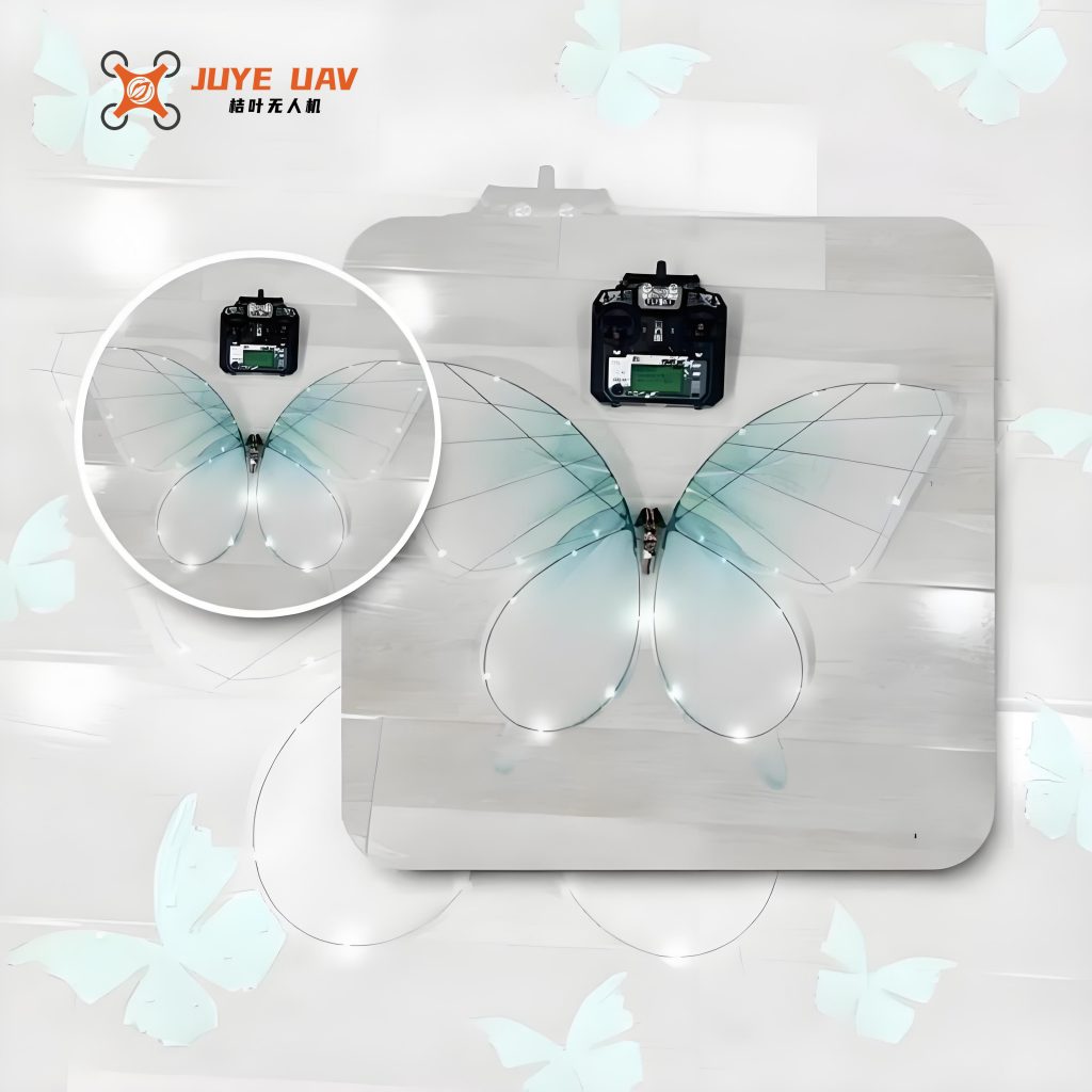
In recent years, numerous studies have investigated insect flight dynamics, revealing complex aerodynamic phenomena like leading-edge vortices, clap-and-fling mechanisms, and rotational circulation. For flying butterfly drones, these principles are adapted to enhance lift production and control. Previous research has led to various prototypes, ranging from piezoelectric-driven micro-robots to motor-driven ornithopters. However, many designs face challenges such as excessive weight, limited payload capacity, or insufficient lift. This work addresses these issues by proposing a servo-driven flying butterfly drone that eliminates complex transmission systems, thereby reducing weight and improving control flexibility. The flying butterfly drone developed here features a wingspan of 49.8 cm, a body length of 37.9 cm, and a total weight of 32.2 g, making it a promising platform for further exploration.
The design process for a flying butterfly drone follows a systematic approach, beginning with conceptual design, preliminary design, detailed design, simulation, fabrication, and testing. This iterative methodology ensures that each component is optimized for performance and manufacturability. Key aspects include aerodynamic analysis, material selection, and integration of control systems. The flying butterfly drone’s wings are designed with flexible membranes supported by carbon fiber veins, mimicking the natural wing structure of butterflies to achieve a balance between strength and lightness. The use of servo motors for direct drive allows precise control over flapping amplitude and frequency, enabling adaptive flight maneuvers.
Aerodynamic Theory of the Flying Butterfly Drone
Understanding the aerodynamic forces acting on a flying butterfly drone is crucial for effective design. The flight of butterflies can be analyzed in two primary modes: flapping motion and gliding motion. In flapping flight, the wings undergo periodic oscillations that generate lift and thrust through unsteady aerodynamic mechanisms. The Reynolds number, which characterizes the flow regime, is defined for insect flight as:
$$Re = \frac{u \cdot c}{v_f}$$
where \(u\) is the average translational velocity at the wingtip, \(c\) is the chord length, and \(v_f\) is the kinematic viscosity of air (approximately \(1.48 \times 10^{-5} \, m^2/s\) for air). For a flying butterfly drone with low flapping frequencies, the Reynolds number typically falls within the range of 100 to 1000, indicating laminar to transitional flow. The wingtip velocity can be expressed as:
$$u = 2 f R \Phi$$
where \(f\) is the flapping frequency, \(R\) is the distance from the wing root to the wingtip, and \(\Phi\) is the peak-to-peak flapping angle in radians. For instance, with a flapping frequency of 1.1 Hz, a wingspan of 0.498 m, and a flapping angle of 136 degrees (2.37 radians), the average wingtip velocity is approximately 0.52 m/s.
The aerodynamic forces on the wings during flapping can be decomposed into lift and drag components. Using the blade element theory, the elemental drag force \(dD\) and lift force \(dL\) on a wing section are given by:
$$dD = \frac{1}{2} \rho C_D V^2 dS$$
$$dL = \frac{1}{2} \rho C_L V^2 dS$$
where \(\rho\) is air density (1.225 kg/m³ at sea level), \(C_D\) and \(C_L\) are the drag and lift coefficients, \(V\) is the relative air velocity, and \(dS\) is the wing section area. For a flying butterfly drone, the coefficients depend on the angle of attack \(\alpha\) and wing morphology. Integrating these forces over the wing span provides the total aerodynamic loads. Additionally, rotational circulation and added mass effects contribute to lift, but for simplicity, this analysis focuses on translational circulation as the primary lift mechanism.
In gliding flight, the flying butterfly drone operates similarly to a fixed-wing aircraft, where lift is generated by pressure differences across the wing due to its camber and angle of attack. The lift force \(F_p\) during gliding can be estimated using the formula:
$$F_p = – \int_{\theta_1}^{\theta_2} \int_{0}^{R} c \rho V^2 \sin^2 \alpha \, dr \, d\theta$$
where \(c\) is a constant related to air viscosity, \(\alpha\) is the angle of attack, and the integration is performed over the wing area. For a flying butterfly drone with a wing area of 8672 mm², a gliding speed of 10 m/s, and an angle of attack of 30 to 45 degrees, the lift per wing is approximately 0.56 N. Thus, the total lift for both wings is about 1.12 N, which exceeds the drone’s weight of 0.316 N (32.2 g), indicating theoretical feasibility for sustained flight. However, practical factors such as drag and control stability must be considered.
The flexibility of wings plays a critical role in enhancing aerodynamic efficiency. Compared to rigid wings, flexible wings exhibit higher lift-to-drag ratios, as demonstrated in Table 1. This table summarizes the lift-to-drag ratios for rigid and flexible wings at various angles of attack, highlighting the superiority of flexible designs for flying butterfly drones.
| Angle of Attack \(\alpha\) (degrees) | Rigid Wing Lift-to-Drag Ratio | Flexible Wing Lift-to-Drag Ratio |
|---|---|---|
| 10 | 5.67 | 11.2 |
| 12 | 4.7 | 9.54 |
| 15 | 3.73 | 7.62 |
| 20 | 2.7 | 5.67 |
| 25 | 2.1 | 4.51 |
| 30 | 1.7 | 3.7 |
| 35 | 1.4 | 3.17 |
These aerodynamic insights guide the structural design of the flying butterfly drone, ensuring that wing flexibility is incorporated to maximize performance.
Structural Design of the Flying Butterfly Drone
The flying butterfly drone is designed with a focus on biomimicry, replicating key features of natural butterfly wings. The overall configuration includes a central body, two wings each divided into a main wing and a forewing, a servo-based drive mechanism, and a control unit. The wings are attached to the body via a carbon fiber frame, allowing for flapping motion driven directly by servos. This direct-drive approach eliminates the need for complex linkages, reducing weight and increasing reliability.
The wing design is crucial for generating sufficient lift. Each wing consists of a carbon fiber vein structure supporting a flexible TPU membrane. The veins are arranged to concentrate mass near the flapping axis, minimizing rotational inertia. The main wing has a triangular fan shape, while the forewing is droplet-shaped, mimicking natural butterfly morphology. The connection between the main wing and forewing is flexible, enabling passive deformation during flapping that enhances aerodynamic efficiency. Specifically, during the downstroke, the wings present a large surface area to generate maximum lift, while during the upstroke, the flexible hinge allows the forewing to lag, reducing drag and maintaining lift.
The flapping motion is controlled by servo motors that rotate the wings about a horizontal axis. The servo provides precise angular positioning, with the flapping angle \(\theta\) ranging from -68 to +68 degrees relative to the horizontal plane, resulting in a total flapping amplitude of 136 degrees. The relationship between servo pulse width and rotation angle is linear, as described by:
$$\theta = k \cdot (PWM – 1.5 \, ms)$$
where \(k\) is a constant, and PWM is the pulse width modulation signal. For a typical servo, a pulse width of 0.5 ms corresponds to 0 degrees, 1.5 ms to 90 degrees, and 2.5 ms to 180 degrees. This allows fine control over the flapping trajectory of the flying butterfly drone.
To validate the structural integrity of the wings, finite element analysis was performed. A force of 2 N was applied at the wing’s center of mass, simulating aerodynamic loads. The results showed a maximum stress of 729 MPa at the wing root, which is well below the yield strength of carbon fiber (3800 MPa), confirming the design’s safety. The displacement analysis indicated minimal deformation, ensuring stable flight performance. These analyses assure that the flying butterfly drone can withstand operational stresses without failure.
Materials and Manufacturing of the Flying Butterfly Drone
Material selection is paramount for achieving a lightweight yet robust flying butterfly drone. The primary materials used include PC-ABS plastic for 3D-printed components, carbon fiber for wing veins, and TPU film for wing membranes. PC-ABS offers a good balance of strength, printability, and cost, with properties summarized in Table 2.
| Property | Value |
|---|---|
| Density (g/cm³) | 1.493 |
| Yield Strength (MPa) | 54.4 |
| Young’s Modulus (GPa) | 2.78 |
| Poisson’s Ratio | 0.4 |
Carbon fiber, specifically T40 grade, was chosen for wing veins due to its high strength-to-weight ratio, as shown in Table 3. This material ensures the wings are both flexible and durable, essential for the flying butterfly drone’s aerodynamic performance.
| Property | Value |
|---|---|
| Density (g/cm³) | 1.76 |
| Tensile Strength (MPa) | 7000 |
| Elastic Modulus (GPa) | 240 |
The wing membrane is made from TPU film, which provides excellent elasticity, tear resistance, and durability. This flexibility allows the wings to deform optimally during flapping, enhancing lift generation. The manufacturing process involves laser cutting the carbon fiber veins, heat-bonding the TPU membrane, and assembling the components with adhesive. The body and servo mounts are 3D-printed using PC-ABS, enabling rapid prototyping and customization.
The servo motor selected for the flying butterfly drone is the D03018MG micro metal-gear digital servo, weighing 3.7 g and providing a torque of 0.5 kg·cm at 4.8 V. This servo allows direct drive of the wings, eliminating the need for additional gears or linkages. The control system is based on an MPU6050 inertial measurement unit (IMU) for attitude sensing and a microcontroller for processing. The entire electronic system is integrated onto a compact PCB, minimizing weight and power consumption.
Assembly of the flying butterfly drone involves attaching the wings to the servos via carbon fiber shafts, securing the servos to the 3D-printed body, and connecting the control electronics. The total weight distribution is critical for balance; Table 4 outlines the weight breakdown of the prototype.
| Component | Weight (g) |
|---|---|
| Total Drone | 32.2 |
| Drive Mechanism | 10.8 |
| Wings | 12.5 |
| Body | 4.1 |
| Electronics and Battery | 4.8 |
This lightweight construction is essential for the flying butterfly drone to achieve lift-off and sustained flight.
Control System and Testing of the Flying Butterfly Drone
The control system for the flying butterfly drone employs a multi-loop PID architecture to stabilize flight attitude. The IMU provides data on angular velocity and acceleration, which are fused using a complementary filter to estimate orientation. The filter combines gyroscope and accelerometer readings to minimize drift and noise, as described by the following equations. The gyroscope data is integrated to obtain angle estimates, while the accelerometer provides gravity reference. The complementary filter blends these sources:
$$\theta_{est} = \alpha (\theta_{gyro} + \omega \Delta t) + (1 – \alpha) \theta_{acc}$$
where \(\theta_{est}\) is the estimated angle, \(\theta_{gyro}\) is the gyroscope-based angle, \(\theta_{acc}\) is the accelerometer-based angle, \(\omega\) is angular velocity, \(\Delta t\) is time step, and \(\alpha\) is a weighting factor typically set between 0.95 and 0.98. This ensures stable attitude estimation for the flying butterfly drone.
The PID controller adjusts servo outputs based on error between desired and actual attitudes. The control law is:
$$u(t) = K_p e(t) + K_i \int e(t) dt + K_d \frac{de(t)}{dt}$$
where \(u(t)\) is the control signal, \(e(t)\) is the error, and \(K_p\), \(K_i\), \(K_d\) are proportional, integral, and derivative gains. For the flying butterfly drone, separate PID loops manage roll, pitch, and yaw, enabling coordinated maneuvers.
Testing of the flying butterfly drone involved lift measurement and motion analysis. A cantilever beam platform with a laser displacement sensor was used to measure lift force. The beam’s deflection under load was calibrated with known weights, yielding a stiffness of 569 N/m. The flying butterfly drone was mounted on the beam, and its flapping motion generated lift, recorded as displacement over time. The data was processed to obtain the lift force curve, as shown in Figure 1. The average lift measured was 0.272 N, which, while substantial, did not fully overcome the drone’s weight due to limitations in flapping frequency and aerodynamic losses.
Flapping kinematics were captured using high-speed cameras at 2900 frames per second. Markers on the wings allowed tracking of flapping and twisting angles. The results indicated a flapping frequency of approximately 1.1 Hz, with a maximum flapping angle of 136 degrees and a twist angle of 30 degrees. These parameters validate the design’s ability to mimic natural butterfly motion, though further optimization is needed to increase lift for free flight.
The flying butterfly drone demonstrates promising performance, but challenges remain in achieving autonomous flight. Future work will focus on enhancing lift through improved wing design, increasing servo efficiency, and implementing advanced control algorithms. The integration of onboard power and sensors will also be crucial for real-world applications.
Conclusion
This study presents a comprehensive approach to designing and manufacturing a flying butterfly drone, inspired by the flight mechanics of natural butterflies. Through aerodynamic analysis, structural design, material selection, and experimental testing, a functional prototype was developed. The flying butterfly drone features direct servo drive, flexible wings, and a lightweight frame, achieving a flapping frequency of 1.1 Hz and a lift force of 0.272 N. While the current model does not sustain free flight due to lift limitations, it provides a foundation for future iterations. Key innovations include the elimination of transmission systems and the use of flexible wing membranes to enhance aerodynamic efficiency. The flying butterfly drone holds potential for applications in surveillance, environmental monitoring, and bio-inspired robotics, with ongoing research aimed at improving lift and control autonomy. As technology advances, flying butterfly drones may become integral to next-generation micro-aerial vehicles, offering unparalleled agility and stealth in diverse operational scenarios.