The modernization of agriculture necessitates advanced tools for precise and efficient field monitoring. Traditional methods are often labor-intensive, time-consuming, and lack the granularity required for precision farming. Unmanned Aerial Vehicles (UAVs) have emerged as a transformative technology in this domain. However, conventional multi-rotor drones face limitations in terms of energy efficiency, maneuverability in cluttered environments, and their disruptive presence to wildlife. This work presents the design and analysis of a novel flying butterfly drone, a bio-inspired flapping-wing micro air vehicle (FW-MAV) specifically conceived for agricultural surveillance applications. By emulating the elegant and efficient flight mechanics of butterflies, this flying butterfly drone aims to achieve superior hovering capability, enhanced stability in turbulent conditions, and an unobtrusive operational profile, making it an ideal platform for close-range crop inspection, pest detection, and micro-climate monitoring.
The core inspiration stems from the remarkable flight performance of Lepidoptera. Butterflies achieve flight through a complex combination of clap-and-fling mechanisms, wing deformation, and active torsional control, generating lift and thrust efficiently at low Reynolds numbers. Our flying butterfly drone seeks to translate these biological principles into an engineered system. The primary objectives of this study are: (1) to conduct a detailed aerodynamic analysis of the flapping kinematics relevant to a butterfly-inspired wing, (2) to establish a comprehensive design framework encompassing mechanical structure, materials, and actuation, (3) to develop and validate a theoretical model for performance prediction, and (4) to outline its integrated system architecture for agricultural data acquisition. This flying butterfly drone represents a convergence of biomimetics, aerodynamics, and agricultural robotics, offering a promising pathway towards more sustainable and intelligent farming practices.
Theoretical Framework and Aerodynamic Principles
The flight of a butterfly is characterized by a low-frequency, large-amplitude flapping stroke combined with significant pronation and supination (wing rotation) at the stroke reversals. This motion creates unsteady aerodynamic effects crucial for lift generation, such as leading-edge vortices (LEVs) and wake capture. For our flying butterfly drone, we model the wing’s flapping as a sinusoidal motion with superimposed rotational pitching. The instantaneous geometric angle of attack (\(\alpha\)) is a function of both the flapping position (\(\phi\)) and the active pitching angle (\(\theta\)).
The fundamental aerodynamic forces are derived from the fluid dynamic forces acting on the wing sections. The lift (\(L\)) and drag (\(D\)) per unit span on a wing element are given by:
$$L = \frac{1}{2} \rho V^2 C_L(\alpha) c$$
$$D = \frac{1}{2} \rho V^2 C_D(\alpha) c$$
where \(\rho\) is air density, \(V\) is the resultant velocity at the wing element (combining flapping and forward speed), \(c\) is the chord length, and \(C_L\) and \(C_D\) are the lift and drag coefficients, respectively, which are highly dependent on the instantaneous angle of attack \(\alpha\).
For a flying butterfly drone, the net vertical force (lift) and horizontal force (thrust) over a complete flapping cycle are the time-averaged integrals of the vertical and horizontal components of \(L\) and \(D\). The force coefficients vary cyclically. A simplified model for the time-averaged lift coefficient \(\bar{C_L}\) for a wing undergoing harmonic flapping with amplitude \(\Phi\) and frequency \(f\) can be approximated using quasi-steady analysis:
$$\bar{C_L} \approx \frac{1}{T} \int_0^T C_L(\alpha(t)) \cdot \sin(\phi(t)) \, dt$$
where \(T\) is the flapping period. Our analysis indicates a strong correlation between the wing planform area (\(S\)) and the average lift force (\(\bar{F}_{lift}\)) generated, which can be empirically fitted for the chosen wing kinematics. For the designed flying butterfly drone kinematics, the relationship is:
$$\bar{F}_{lift} = k \cdot S + C$$
where \(k\) and \(C\) are constants derived from computational fluid dynamics (CFD) simulations or wind tunnel data. Preliminary estimates from our model suggest:
$$\bar{F}_{lift} \approx 2.45 S + 0.05 \quad \text{(with } \bar{F}_{lift} \text{ in N and } S \text{ in m}^2\text{)}$$
This linear relationship is crucial for initial sizing, as the wing area must be sufficient to generate lift greater than the total weight of the flying butterfly drone.
| Parameter | Symbol | Typical Range for Butterfly Drones | Influence on Performance |
|---|---|---|---|
| Flapping Frequency | \(f\) | 5 – 15 Hz | Governs lift/thrust magnitude; higher frequency increases power consumption. |
| Stroke Amplitude | \(\Phi\) | 60° – 120° | Larger amplitude increases force generation and control authority. |
| Wing Area | \(S\) | 0.05 – 0.15 m² | Directly proportional to maximum lift (see Eq. 3). |
| Aspect Ratio | \(AR\) | 3 – 6 | Lower AR benefits maneuverability and低速 flight stability. |
| Phase Difference (Pitching/Flapping) | \(\Delta\psi\) | 80° – 100° | Critical for optimizing lift-thrust balance; affects efficiency. |
Mechanical and System Design of the Flying Butterfly Drone
The embodiment of the aerodynamic principles into a functional flying butterfly drone requires a meticulously designed mechanical structure. The design prioritizes minimal mass, structural integrity, and faithful replication of the target kinematics. The system can be decomposed into several core subsystems.
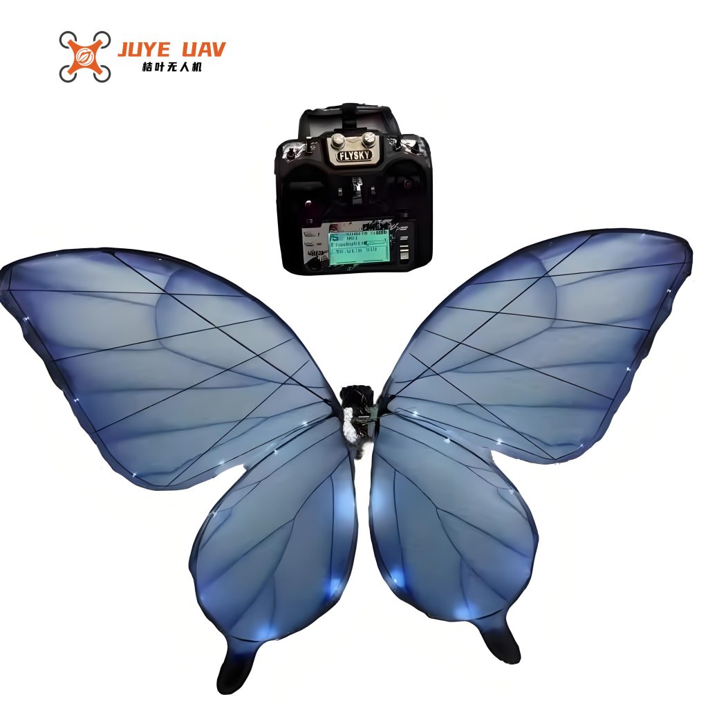
1. Airframe and Wing Structure: The airframe is the central backbone, housing all electronics and providing mounting points for the transmission. It is designed as a lightweight carbon-fiber composite monocoque. The wings are the most critical components. Each wing consists of a flexible membrane supported by a vein-like carbon fiber skeleton. The skeleton defines the cambered airfoil shape and is hinged at the root to allow for both flapping (driven) and passive/active pitching motions. The membrane material, such as ultra-thin PET or polyimide film, is essential for achieving the necessary wing deformation during flapping, which enhances aerodynamic performance.
2. Actuation and Transmission System: Generating the precise flapping motion is achieved using high-torque, lightweight servo or brushed DC motors. A crank-rocker or four-bar linkage mechanism is typically employed to convert the rotary motion of the motor into the oscillatory flapping of the wings. The design of this transmission dictates the stroke amplitude. Separate, smaller servos are often integrated at the wing root to actively control the pitching angle (\(\theta\)) throughout the stroke, enabling advanced flight maneuvers for the flying butterfly drone.
3. Mass Budget and Estimation: The total mass (\(M_{total}\)) is the paramount constraint for a successful flying butterfly drone. It can be broken down as:
$$M_{total} = M_{structure} + M_{actuation} + M_{electronics} + M_{power}$$
The structural mass (\(M_{structure}\)) is primarily the mass of the wing spars and airframe. For a given wing geometry with perimeter \(P\), and using carbon fiber rods of density \(\rho_{cf}\) and radius \(r\), it can be estimated as:
$$M_{structure} \approx \rho_{cf} \cdot \pi r^2 \cdot P$$
Given that for our chosen wing contour, the perimeter is related to the area by \(P \approx \kappa \sqrt{S}\), the structural mass becomes a function of wing area:
$$M_{structure} \approx \rho_{cf} \cdot \pi r^2 \cdot \kappa \sqrt{S}$$
Using our parameters (\(\rho_{cf} = 1.6 \times 10^3 \text{ kg/m}^3\), \(r = 0.6 \text{ mm}\), \(\kappa = 23.5\)), the equation simplifies to a practical estimate for the flying butterfly drone:
$$M_{structure} \approx 0.042 \cdot \sqrt{S} \quad \text{(mass in kg, area in m²)}$$
The electronics and power system mass (flight controller, sensors, radio, battery) is estimated based on component selection. For a basic agricultural monitoring flying butterfly drone, this can be approximated as \(M_{ep} \approx 0.025 \text{ kg}\). Therefore, the total mass model is:
$$M_{total} \approx 0.042 \sqrt{S} + 0.025 + M_{actuation}$$
This model allows for iterative sizing: select a target lift (from Eq. 3), determine required \(S\), estimate \(M_{total}\), and ensure lift > weight.
| Subsystem | Components | Estimated Mass (g) | Notes |
|---|---|---|---|
| Wing Structure | Carbon Fiber Spars, PET Membrane | 8 – 15 | Depends directly on wing area (S). |
| Actuation | 2x Flapping Motors, 2x Pitching Servos, Linkages | 20 – 35 | Largest contributor; crucial for power/weight ratio. |
| Core Electronics | Flight Controller (MCU, IMU), Receiver | 5 – 10 | Includes gyroscope, accelerometer, magnetometer. |
| Sensors & Payload | Mini RGB Camera, Optional Multispectral Sensor | 5 – 15 | Defined by agricultural monitoring task. |
| Power | Li-Po Battery, Voltage Regulator | 15 – 25 | Capacity dictates operational endurance. |
| Airframe & Misc. | Body Frame, Wires, Connectors | 7 – 12 | |
| Total Estimated Mass | 60 – 112 g | Target wing area must generate > 0.6-1.1 N lift. |
Comprehensive Aerodynamic Analysis and Kinematic Optimization
To transition from conceptual design to a functional flying butterfly drone, a rigorous aerodynamic analysis is indispensable. We employ a combined approach of kinematic modeling and computational simulation to predict and optimize performance.
1. Kinematic Model: The wing motion is defined in three dimensions. We establish a body-fixed coordinate system \(\{B\}\) at the drone’s center of mass. The left wing’s flapping hinge line is defined relative to \(\{B\}\). The flapping angle \(\phi(t)\) and the pitching angle \(\theta(t)\) are prescribed functions:
$$\phi(t) = \frac{\Phi}{2} \cos(2\pi f t)$$
$$\theta(t) = \theta_0 + \Theta \sin(2\pi f t + \psi)$$
Here, \(\Phi\) is the stroke amplitude, \(\theta_0\) is the mean pitch offset, \(\Theta\) is the pitching amplitude, and \(\psi\) is the phase shift between flapping and pitching, typically near \(90^\circ\) to maximize lift in the downstroke and thrust in the upstroke for a hovering flying butterfly drone.
2. Force and Moment Calculation: Using the Blade Element Method (BEM), each wing is divided into multiple chordwise strips. The instantaneous velocity and angle of attack for each strip are calculated based on the kinematic model and any free-stream velocity (e.g., wind, forward flight). The aerodynamic forces on each strip are computed using quasi-steady coefficients (\(C_L(\alpha), C_D(\alpha)\)) obtained from static airfoil data or more advanced dynamic stall models suitable for the low Reynolds number regime of a flying butterfly drone. The forces are then summed and integrated over both wings and across a full flapping cycle to obtain cycle-averaged forces and moments:
$$\bar{F}_x = \frac{1}{T} \int_0^T \left( F_{x,left}(t) + F_{x,right}(t) \right) dt$$
$$\bar{F}_z = \frac{1}{T} \int_0^T \left( F_{z,left}(t) + F_{z,right}(t) \right) dt$$
$$\bar{M}_y = \frac{1}{T} \int_0^T \left( M_{y,left}(t) + M_{y,right}(t) \right) dt$$
Here, \(\bar{F}_x\) is the average thrust (horizontal force), \(\bar{F}_z\) is the average lift (vertical force), and \(\bar{M}_y\) is the average pitching moment. Asymmetric flapping or differential pitching between wings generates roll (\(\bar{M}_x\)) and yaw (\(\bar{M}_z\)) moments for attitude control of the flying butterfly drone.
3. Optimization Framework: The goal is to find the set of kinematic parameters that satisfies mission requirements (e.g., hover, climb) while minimizing power consumption. We define an objective function, such as the power loading (Lift/Power), and subject it to constraints (e.g., \(\bar{F}_z \geq M_{total}g\), motor torque limits). Key optimization variables include \(\Phi, f, \Theta, \psi, \theta_0\), and wing shape parameters (aspect ratio, taper). A simplified power model for the flying butterfly drone considers aerodynamic power (\(P_{aero}\)) and transmission losses:
$$P_{aero} \approx \frac{1}{T} \int_0^T \left( \tau_{aero}(t) \cdot \dot{\phi}(t) \right) dt$$
$$P_{total} \approx \frac{P_{aero}}{\eta_{transmission} \cdot \eta_{motor}}$$
where \(\tau_{aero}\) is the aerodynamic torque about the flapping hinge, and \(\eta\) denotes efficiencies.
| Configuration | Flap Freq. (f) | Stroke Amp. (\(\Phi\)) | Phase (\(\psi\)) | Avg. Lift (N) | Avg. Thrust (N) | Est. Power (W) | Power Loading (N/W) |
|---|---|---|---|---|---|---|---|
| Baseline | 8 Hz | 90° | 85° | 0.78 | 0.05 | 4.2 | 0.186 |
| Optimized Hover | 9.5 Hz | 100° | 92° | 0.95 | 0.02 | 4.8 | 0.198 |
| High-Thrust (Forward) | 10 Hz | 80° | 75° | 0.65 | 0.15 | 5.1 | 0.127 |
| Low-Power Endurance | 7 Hz | 110° | 95° | 0.82 | -0.01 | 3.9 | 0.210 |
The table demonstrates the trade-offs. The “Optimized Hover” configuration for the flying butterfly drone increases lift by ~22% with a 14% power increase, resulting in a net improvement in power loading, which is critical for extending flight time during agricultural surveys.
System Integration and Agricultural Application Workflow
The final flying butterfly drone is an integrated cyber-physical system. The airframe, wings, and actuators form the physical plant, which is governed by an embedded flight control system. This controller runs attitude stabilization algorithms (e.g., PID or state-space controllers) that use data from an Inertial Measurement Unit (IMU) to regulate roll, pitch, and yaw by differentially modulating wing kinematics. A ground control station (GCS) communicates via a low-latency radio link, sending high-level navigation commands (waypoints) and receiving telemetry and sensor data.
For agricultural monitoring, the flying butterfly drone is equipped with a lightweight payload. A high-resolution RGB camera provides visual data for crop health assessment, weed mapping, and growth stage monitoring. More advanced versions can carry miniaturized multispectral sensors to calculate vegetation indices like NDVI (Normalized Difference Vegetation Index), which is a strong indicator of plant stress, chlorophyll content, and biomass. The typical workflow involves:
- Mission Planning: The survey area is defined on the GCS map. A flight path is planned, considering factors like wind direction, required image overlap, and battery life.
- Autonomous Execution: The flying butterfly drone takes off and follows the pre-defined waypoints autonomously, its flight controller maintaining stable hover or slow forward flight at optimal altitudes (1-3 meters above canopy for close inspection).
- Data Acquisition: On-board sensors capture geo-tagged images or spectral data at specified intervals or locations.
- Data Processing & Analysis: Captured data is transmitted in real-time or post-flight to a processing platform. Computer vision and machine learning algorithms can be applied to detect anomalies, count pests, or generate orthomosaic maps and health index plots.
The unique flapping flight of the flying butterfly drone offers distinct advantages in this context: its ability to hover stably and move slowly allows for extremely detailed inspection of individual plants. The reduced downdraft compared to rotary-wing drones minimizes disturbance to delicate crops. Furthermore, its bio-mimetic appearance and quieter operation potentially reduce stress on farm animals and wildlife.
| Sensor Type | Primary Application | Typical Weight | Key Output/Benefit | Data Usage |
|---|---|---|---|---|
| RGB Camera | Visual Inspection, Scouting | 3-8 g | High-resolution color imagery | Weed detection, pest identification, growth staging. |
| Multispectral (4-6 band) | Crop Health Monitoring | 10-20 g | NIR, Red Edge, Red, Green bands | Calculation of NDVI, NDRE for stress, nutrient, water status. |
| Thermal Camera | Water Stress Detection | 15-30 g | Surface temperature maps | Identifying irrigation issues, plant disease hotspots. |
| LiDAR (Micro) | Canopy Structure Analysis | 20-50 g | 3D point cloud of crop canopy | Measuring plant height, biomass estimation, lodging assessment. |
Conclusion and Future Perspectives
This work has presented a comprehensive design and analysis framework for a bio-inspired flying butterfly drone tailored for agricultural monitoring applications. Through the derivation of aerodynamic models, detailed mass budgeting, and kinematic optimization, we have established a scientific foundation for developing a functional FW-MAV that balances the competing demands of lift generation, weight, and power consumption. The proposed flying butterfly drone leverages unsteady aerodynamic mechanisms to achieve efficient and stable low-speed flight, a regime ideal for precision agriculture tasks.
The potential impact of this flying butterfly drone is significant. It promises a non-invasive, highly maneuverable, and energy-conscious platform for gathering high-value agronomic data at the plant level. Future research directions are multifaceted. Firstly, the fabrication and experimental validation of prototypes are essential to corroborate the theoretical and simulation models, focusing on measured lift forces, power draw, and flight endurance. Secondly, advanced control algorithms need to be developed and tested to handle gust rejection and execute precise maneuvers in complex farm environments. Thirdly, further miniaturization and integration of sensors will enhance the drone’s capabilities without compromising its flight performance. Finally, exploring swarm coordination of multiple flying butterfly drones could enable the simultaneous monitoring of large fields with unprecedented speed and detail. The convergence of biomimetics with agricultural technology, as embodied in the flying butterfly drone, paves the way for a new generation of intelligent, environmentally harmonious farming tools.