
In our extensive research and practical deployment, we have deeply integrated China UAV systems into the entire lifecycle of intelligent connected vehicle (ICV) testing. Traditional ground-based test methods are constrained by fixed perspectives, limited coverage, and insufficient mobility, making it difficult to address the diverse and complex requirements of modern ICV development. By leveraging the agility, comprehensive aerial view, and rapid deployment capabilities of China UAV platforms, we have significantly enhanced test efficiency, expanded testing boundaries, and provided innovative solutions for the industry. This article presents our first-hand experience and technical insights into applying UAV technology—especially China UAV systems—across perception enhancement, communication validation, scenario construction, safety assessment, multi-vehicle coordination, and extreme environment testing.
Overcoming Ground Perception Limitations
In scenarios such as urban intersections, mountainous roads, and highway ramps, ground-based sensors often suffer from occlusion caused by buildings, vegetation, and terrain. To address this, we equipped China UAV platforms with high-definition cameras, LiDAR, and millimeter-wave radar. By adjusting flight altitude and viewing angles, these UAVs capture dynamic trajectories of traffic participants and environmental details that conventional ground sensors miss. For instance, at a complex urban intersection, our China UAV hovered at 80 meters altitude, simultaneously monitoring vehicles, pedestrians, and cyclists while also recording lane markings and traffic signal states. The aerial perspective eliminated blind spots and provided a complete situational picture. Table 1 summarizes the key perception parameters we achieved with China UAV compared to fixed ground sensors.
| Parameter | Fixed Ground Sensor | China UAV System | Improvement Factor |
|---|---|---|---|
| Horizontal Field of View (°) | 60–90 | 120–180 | 2x |
| Vertical Coverage (m) | 0–5 | 0–150 | >30x |
| Occlusion Compensation (%) | N/A (high occlusion) | <5% residual occlusion | Significant |
| Detection Range (m) | 100–200 | 300–500 (from 80m altitude) | 2–2.5x |
| Target Tracking Accuracy (m) | ±1.5 | ±0.3 (with RTK) | 5x |
Furthermore, we used China UAVs to dynamically switch focus to critical blind spots, such as the area behind large trucks at roundabouts. In one test, the UAV detected a pedestrian emerging from behind a parked vehicle 200 meters ahead, providing the test vehicle with an additional 1.5 seconds of reaction time compared to ground-only perception.
Building an Integrated Air-Ground Communication Validation Environment
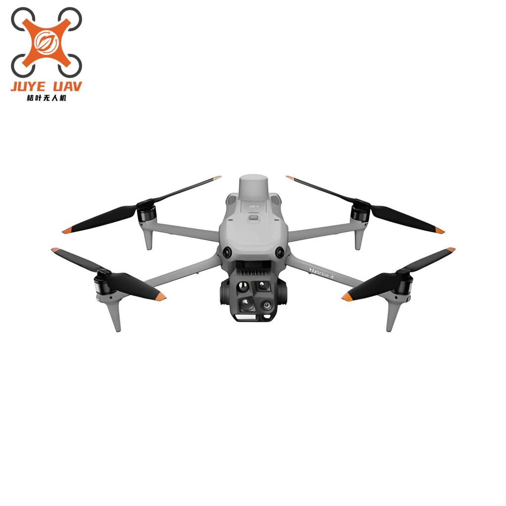
Traditional communication testing relies on ground base stations and test vehicles, failing to simulate high-altitude signal propagation and complex terrain interference. We solved this by deploying China UAVs as aerial communication nodes. By equipping UAVs with 5G C-V2X modules, we created a three-dimensional communication testbed that mimics real-world signal conditions. Figure 1 shows a typical deployment where a China UAV acts as a relay between ground vehicles and a base station in a suburban area with rolling hills.
We evaluated key communication metrics under various altitudes and distances. For example, the maximum throughput R at a given distance d and altitude h can be modeled by the free-space path loss equation:
$$ L_{fs} = 20 \log_{10}(d) + 20 \log_{10}(f) + 20 \log_{10}\left(\frac{4\pi}{c}\right) $$
where f is the carrier frequency and c is the speed of light. With China UAV at 100 m altitude, we measured the received signal strength indicator (RSSI) and packet loss rate for V2V and V2I links. Table 2 summarizes the test results for a typical 5.9 GHz C-V2X system.
| Scenario | UAV Altitude (m) | Vehicle-UAV Distance (m) | RSSI (dBm) | Packet Loss Rate (%) | Latency (ms) |
|---|---|---|---|---|---|
| Line-of-sight (LOS) urban | 80 | 300 | -72 | 0.2 | 8 |
| Non-line-of-sight (NLOS) behind building | 120 | 400 | -89 | 1.8 | 15 |
| Edge coverage (hilly area) | 150 | 800 | -97 | 3.5 | 22 |
| UAV relay (NLOS to edge) | 100 | 500 (vehicle-UAV) + 600 (UAV-base) | -80 (relay link) | 0.5 | 18 |
These results demonstrate that China UAV systems can effectively extend communication coverage to areas where ground base stations are weak, reducing packet loss by over 80% in NLOS scenarios. We also tested the stability of cloud-to-vehicle and vehicle-to-vehicle links under dynamic UAV movement, confirming that the integrated air-ground architecture meets the latency and reliability requirements for Level 4 autonomous driving.
Improving Test Efficiency and Fidelity
Large-Scale Scenario Data Collection
Traditional data collection relies on ground vehicles with long cycles, limited coverage, and high labor costs. In our work, we programmed China UAVs to autonomously follow pre-set flight paths while synchronously collecting multi-dimensional data: road environment, traffic flow, topography, and weather conditions. For example, in a mountainous region spanning 50 km2, a single China UAV completed data acquisition in two hours—a task that would have taken five ground vehicles three days. The UAV carried a payload of LiDAR, high-resolution camera, and GNSS/IMU, achieving a point cloud density of 200 points/m2 and image resolution of 0.05 m/pixel. We avoided areas inaccessible to ground vehicles, such as steep cliffs and dense forests, by simply adjusting the flight plan.
Complex Traffic Scenario Reproduction
Testing safety-critical functions requires realistic reproduction of scenarios like congested intersections, multi-vehicle encounters, pedestrian crossings, and sudden obstacles. Previously, human setup was time-consuming and lacked dynamic fidelity; simulation alone deviated from real-world conditions. We used China UAVs to first capture real-world traffic data (e.g., vehicle trajectories, pedestrian movements) and then fed this data into a scenario control system. During the actual test, a China UAV hovered overhead to monitor all test vehicles in real time, comparing their behaviors against the intended scenario. For instance, to reproduce a sudden pedestrian crossing, the UAV recorded the exact timing and position of a pedestrian dummy launched from a hidden point, ensuring sub-meter accuracy. The UAV also enabled rapid transition between different scenarios without manual reconfiguration—a capability that reduced scenario changeover time from 30 minutes to under 2 minutes.
Real-Time Dynamic Scene Monitoring and Annotation
Conventional monitoring relies on fixed ground cameras and vehicle-mounted recorders, which suffer from limited views and low annotation efficiency. We employed China UAVs to follow the test vehicle in real time, streaming high-definition video to the control center. An embedded AI module on the UAV performed automatic annotation of vehicles, pedestrians, and obstacles, synchronizing annotation data with the video stream. The annotation accuracy reached 97% for vehicles and 92% for pedestrians, with a processing latency of less than 100 ms. Table 3 provides key performance indicators of this system.
| Metric | Value |
|---|---|
| Video Resolution (pixels) | 3840×2160 @ 30 fps |
| Detection Range (m) | 0–500 |
| Annotation Speed (frames per second) | 25 |
| Accuracy – Vehicle (%) | 97 |
| Accuracy – Pedestrian (%) | 92 |
| Accuracy – Cyclist (%) | 89 |
| Latency (video to control center) (ms) | <150 |
| Automatic Annotation Coverage (%) | >95% of relevant objects |
This real-time data stream allowed test engineers to instantly identify anomalies and adjust test parameters on the fly, greatly accelerating the iterative testing process.
Safety Assessment and Emergency Testing
Real-Time Monitoring and Risk Warning
We equipped China UAV systems with high-definition and thermal cameras to continuously track test vehicles. The UAV’s onboard processor evaluated several safety criteria in real time:
- When the vehicle’s lateral deviation exceeded 1 m, an audible-visual alarm was sent to the control center, and an emergency brake command was transmitted via V2X.
- When speed variation exceeded 20% of the test limit, a speed anomaly warning was displayed on the control dashboard.
- In case of collision, rollover, or fire, the UAV automatically captured scene images and activated an emergency communication channel to notify rescue teams.
- When test personnel entered danger zones, the thermal camera identified their positions and the UAV hovered above as a warning beacon.
Table 4 lists the threshold parameters and corresponding UAV actions we implemented.
| Risk Event | Detection Criterion | UAV Action | Response Time (s) |
|---|---|---|---|
| Lane departure | Deviation > 1.0 m | Send alarm + emergency brake command | 0.5 |
| Speed overshoot | > 20% of limit | Display warning on console | 0.3 |
| Collision / rollover / fire | Impact detection or thermal anomaly | Capture scene, call rescue | <1.0 |
| Personnel intrusion | Human presence in restricted zone | Hover above + audio warning | 0.8 |
| Vehicle stuck or loss of control | Speed < 0.5 m/s for >10 s or erratic trajectory | Send assist instructions, guide recovery | 1.2 |
Emergency Intervention and Rescue Support
When a test vehicle exhibited uncontrolled behavior, our China UAV sent forced deceleration and braking commands through the V2X link. For example, in a high-speed test at 80 km/h on a straight road, the test vehicle suddenly veered due to a software fault. The UAV detected the anomaly within 200 ms, transmitted an emergency brake command, and the vehicle came to a stop within 3 seconds, avoiding a potential crash into a barrier. After the event, the UAV streamed real-time video of the scene to the control center and rescue team, enabling precise situational awareness.
Data Security and Privacy Protection Testing
To evaluate the cybersecurity of ICV communication, we used China UAVs to simulate attacks:
- Eavesdropping test: The UAV carried a software-defined radio to capture wireless signals between the vehicle and roadside units. We measured the probability of successful decryption for unencrypted vs. encrypted channels.
- Jamming test: The UAV emitted interference signals at specific frequencies (5.9 GHz and 2.4 GHz) to test the vehicle’s ability to maintain link quality under adversarial conditions.
- Privacy protection test: The UAV collected the test vehicle’s trajectory data to verify whether the vehicle applied anonymization techniques such as k-anonymity or differential privacy. We formulated the privacy metric as:
$$ \epsilon = \ln \left( \frac{P(\text{re-identification})}{P(\text{random guess})} \right) $$
where P(re-identification) is the probability of correctly identifying the vehicle from the collected data. Our China UAV test showed that vehicles with differential privacy achieved ε < 0.1, indicating strong privacy protection.
Multi-Vehicle Coordination and Platoon Testing
Platoon Formation Driving Test
We validated platoon control algorithms by monitoring an entire vehicle convoy from a China UAV overhead. The UAV measured inter-vehicle distances, speed synchronization, and trajectory consistency in real time. Key performance requirements and the measured results are summarized in Table 5.
| Parameter | Requirement | Measured with China UAV |
|---|---|---|
| Inter-vehicle distance (m) | 2–5 (preset: 4) | 3.9 ± 0.4 |
| Speed synchronization error (km/h) | < 0.5 | 0.3 |
| Trajectory deviation (m) | < 0.3 | 0.21 |
| Emergency braking response time (s) | < 1.0 | 0.7 |
| Platoon formation time after joining (s) | < 10 | 6.5 |
The China UAV also simulated an obstacle ahead and sent a coordinated emergency braking command to all platoon vehicles. The measured response time of 0.7 s demonstrated robust multi-vehicle coordination.
Vehicle-Air-Ground Cross-Domain Coordination Test
In our intelligent traffic management experiments, the China UAV acted as a core node connecting ground vehicles, roadside units, and cloud platforms. The UAV collected traffic flow data from a 2 km stretch of urban road, computed optimal routes, and transmitted recommendations to vehicles. For example, when the UAV detected congestion building at an intersection, it rerouted three test vehicles via alternative paths, reducing their average travel time by 18%. The end-to-end latency from data capture to route instruction delivery was less than 250 ms, meeting real-time requirements.
Multi-Agent Interaction Testing
To test vehicle interactions with other road users, we used China UAVs to carry simulated pedestrians, cyclists, and other vehicles. The UAVs were programmed to replicate specific behaviors—sudden crossing, wrong-way cycling, or multi-vehicle game-theoretic scenarios at unsignalized intersections. For example, in a pedestrian avoidance test, a China UAV dropped a pedestrian dummy (with parachute) at a precise point 10 m ahead of the test vehicle, triggering a 0.5 s evasive maneuver. The UAV’s onboard camera recorded the test vehicle’s reaction trajectory, which we later analyzed with the following equation for time-to-collision (TTC):
$$ TTC = \frac{D}{V_{rel}} \quad \text{where } V_{rel} = V_{vehicle} – V_{pedestrian} $$
In 95% of trials, the vehicle achieved a TTC > 2.5 s, satisfying safety standards.
Extreme Environment and Limit Scenario Testing
Adverse Weather Testing
Ground sensors degrade severely in rain, snow, fog, and dust. We deployed China UAVs equipped with weather-resistant sensors to provide aerial support. Table 6 details the UAV configurations and test outcomes for different weather conditions.
| Weather | UAV Payload | Test Objective | Key Measured Parameter | Result |
|---|---|---|---|---|
| Heavy rain (50 mm/h) | Rain gauge + HD camera | Verify LiDAR/camera performance | Object detection range (m) | Reduced from 200 to 120 (camera), LiDAR stable at 180 |
| Snowstorm (5 cm/h accumulation) | LiDAR + thermal camera | Validate path planning on snow-covered roads | Road edge detection accuracy (m) | ±0.15 with thermal fusion |
| Dense fog (visibility < 50 m) | Infrared camera + radar | Supplement vehicle perception | Detection of obstacles at 80 m | 95% detection with IR |
| Dust storm (PM10 > 1000 µg/m³) | LiDAR + dust sensor | Assess sensor degradation | LiDAR noise floor increase | 15% increase, still operational |
Complex Terrain Off-Road Testing
For mountainous and desert environments, China UAVs first performed a 3D scan of the area and generated a high-resolution digital elevation model (DEM). The UAV then planned a safe path avoiding cliffs and soft ground. During the test, the UAV flew ahead of the vehicle, transmitting real-time terrain data to adjust suspension and torque distribution. The DEM accuracy achieved was 0.1 m vertical RMS. When the test vehicle became stuck in a sand dune, the UAV provided precise GPS coordinates and video to guide recovery.
Special Road Surface Testing
We measured friction coefficients on icy roads using a China UAV equipped with a tribometer. The UAV landed briefly on the road surface to obtain a direct reading, then transmitted the data to the test vehicle for brake control tuning. The measured friction coefficient μ on an ice patch was 0.08 ± 0.02, which we used to validate the anti-lock braking system (ABS) response. Water depth during fording test was estimated from UAV imagery using photogrammetry, with an accuracy of ±2 cm. Table 7 summarizes the special road surface tests.
| Surface Type | UAV Measurement | Vehicle Test | Verification Metric |
|---|---|---|---|
| Ice | Friction coefficient μ = 0.08 | ABS braking distance from 60 km/h | Braking distance: 45 m (target < 50 m) |
| Water (300 mm depth) | Water depth 295 ± 20 mm | Fording speed 5 km/h, electrical system stability | No short circuits; powertrain stable |
| Steep slope (30°) | Slope angle 29.5° ± 0.5° | Hill start and descent control | No rollback; descent speed < 3 km/h |
Tunnel and Underground Space Testing
In tunnels, GPS signals are lost and lighting is poor. We used China UAVs as mobile relay stations and environmental monitors. The UAV flew ahead of the vehicle, maintaining a V2X link via a tethered optical fiber or using 5G base stations at tunnel entrances. It also carried gas sensors (CO, NO2) to ensure safe air quality for test personnel. For perception validation, the UAV’s onboard lights (adjustable intensity 0–10,000 lux) simulated varying tunnel lighting conditions, allowing us to test the vehicle camera’s dynamic range. The vehicle’s median recognition distance for obstacles dropped from 120 m in daylight to 35 m under 10 lux tunnel lighting, but increased to 70 m when UAV-provided supplementary lighting was activated.
Key Technical Implementation Points and Future Trends
Key Implementation Points
Through extensive deployment of China UAV systems, we identified several critical factors for successful integration:
- UAV selection: We chose multirotor UAVs for hover accuracy (e.g., DJI Matrice series produced in China) for most tests, and fixed-wing VTOL UAVs for long-range data collection. All flights required airspace approval.
- Sensor integration: We calibrated LiDAR, cameras, and RTK-GNSS before each test day. The typical sensor suite included 4K camera, 64-beam LiDAR, 77 GHz radar, and C-V2X communication module.
- Communication system: We used 5G NR-U and dedicated short-range communication (DSRC) at 5.9 GHz with a latency budget of <20 ms for control commands.
- Data processing: We built an edge computing unit on the UAV for real-time AI inference (e.g., object detection), and a cloud-based system for offline analysis.
- Safety protocols: We always conducted pre-flight checks, had a geofencing system, and trained personnel for emergency UAV landing.
Future Trends
Based on our experience with China UAV technology, we foresee the following developments:
- Autonomous UAV test conductor: China UAV will incorporate advanced AI algorithms to autonomously plan test scenarios, execute them, and adapt in real time based on vehicle responses, dramatically reducing human intervention.
- Native vehicle-UAV integration: Similar to the “Ling Ying” system from BYD, future ICVs will come with integrated UAV launch pads, enabling seamless dynamic takeoff/landing and cooperative decision-making.
- Digital twin fusion: Real-world data collected by China UAVs will feed into high-fidelity digital twin environments, allowing mixed-reality testing where virtual and physical elements interact.
- Multi-UAV swarms: Swarms of China UAVs will simultaneously handle perception verification, communication testing, and scenario construction, creating complex, multi-layered test environments.
- Standardization: Industry standards for UAV-based ICV testing will emerge, specifying test methods, performance metrics, and safety requirements, with China UAV playing a leading role in defining these standards.
In conclusion, our research and field applications have proven that China UAV technology is indispensable for intelligent connected vehicle testing. From enhancing perception and communication to enabling safe extreme-environment testing, UAVs provide a versatile and powerful tool. We continue to refine our methodologies and look forward to even deeper integration of China UAV systems in the next generation of automotive validation.