
The scale and complexity of modern industrial park construction projects have increased dramatically, making slope stability a paramount factor for overall engineering safety. Traditional slope monitoring methods, often reliant on manual surveys and fixed instrumentation, present significant limitations. They struggle to provide the high precision, frequent temporal coverage, and extensive spatial coverage required for proactive risk management in large, dynamic construction sites. In this context, Unmanned Aerial Vehicle (UAV) technology, with its advantages of operational flexibility, high-resolution imaging, and rapid data acquisition, has emerged as a transformative tool. This study, drawing from experience in a major logistics hub development, delves into the application of UAV drones for slope monitoring, examining their technical principles, multifaceted value, and detailed methodological implementation to ensure project safety and facilitate smooth construction progress.
An Overview of UAV Technology
An Unmanned Aerial Vehicle (UAV), or drone, is an aircraft operated without a human pilot onboard, controlled either remotely via radio or autonomously by onboard computers. UAV drones come in various configurations, each suited to specific mission profiles. Their system architecture is generally composed of several integrated subsystems:
- Airframe: The physical structure (wings, fuselage, landing gear). Material selection and aerodynamic design are crucial for endurance, stability, and payload capacity.
- Flight Control System (FCS): The “brain” of the UAV drone. It uses sensors like accelerometers, gyroscopes, and barometers to maintain stable flight, navigate along predefined routes, and execute automated missions.
- Data Link System: Establishes the communication bridge between the UAV drone and the ground control station (GCS), enabling command transmission and real-time telemetry/data downlink.
- Payload: The mission-specific equipment carried by the UAV drone, such as optical cameras, multispectral sensors, or Light Detection and Ranging (LiDAR) units.
- Ground Control Station (GCS): The interface for operators to plan missions, monitor flight status, and control the UAV drone.
The choice of UAV drone platform depends on the monitoring requirements. The following table summarizes common types:
| UAV Drone Type | Key Characteristics | Typical Use Case in Slope Monitoring |
|---|---|---|
| Fixed-Wing | Long endurance, high speed, large coverage per flight. | Rapid initial topographic mapping of very large project sites or long linear slopes. |
| Multi-Rotor (e.g., Quadcopter, Hexacopter) | Vertical Take-Off and Landing (VTOL), excellent maneuverability, ability to hover. | High-resolution, repeat imaging of specific slope faces; monitoring in complex, confined areas; frequent inspection flights. |
| VTOL Fixed-Wing Hybrid | Combines VTOL convenience with fixed-wing efficiency. | Projects requiring both extensive coverage and the ability to closely inspect points of interest without separate platforms. |
The Application Value of UAV Drones in Slope Monitoring
The integration of UAV drones into slope monitoring protocols offers substantial value across multiple dimensions, fundamentally enhancing how geotechnical risks are managed.
1. Unprecedented Monitoring Efficiency and Coverage: UAV drones can rapidly survey vast and often inaccessible slope areas. A single flight can systematically capture data from several square kilometers in a matter of minutes—a task that would require days or weeks for a ground crew. This enables frequent, repeat surveys (e.g., weekly, post-rainfall, or after significant excavation), creating dense time-series data crucial for understanding slope behavior. The efficiency of UAV drones allows for monitoring at temporal and spatial scales previously impractical, transforming reactive monitoring into a proactive process.
2. Enhanced Data Accuracy and Richness: Modern UAV drones are equipped with high-precision sensors. Optical cameras with stabilized gimbals capture centimeter-level ground resolution imagery, revealing fine details like crack initiation, surface erosion, and construction progress. LiDAR payloads emit laser pulses to generate extremely accurate 3D point clouds of the terrain. A key advantage of LiDAR on UAV drones is its ability to penetrate sparse vegetation, capturing the true ground surface topology, which is critical for accurate volume calculations and change detection. The data from UAV drones provides a reliable, quantitative foundation for stability analysis.
3. Improved Personnel Safety and Access: Slope monitoring often involves hazardous terrain—steep, unstable, or undercut slopes. Sending personnel into these zones for manual measurements carries inherent risk. UAV drones eliminate this exposure by remotely accessing dangerous areas, collecting data from safe standoff positions. This not only protects surveyors and engineers but also allows for the inspection of areas that are physically unreachable.
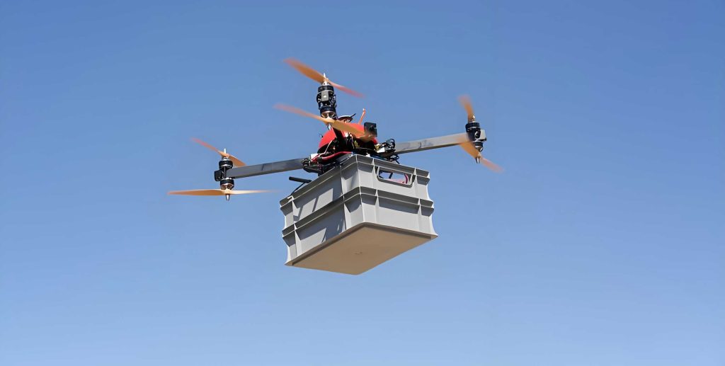
4. Comprehensive and Integrated Monitoring Perspective: UAV drones provide a synoptic, bird’s-eye view of the entire project site. This holistic perspective is invaluable for understanding the spatial relationships between different slope sections, drainage patterns, and construction activities. Data from UAV drones can be seamlessly integrated with other geospatial datasets (e.g., GIS, BIM models) and data from traditional in-situ sensors (e.g., inclinometers, piezometers), creating a multi-source, multi-scale digital twin of the slope for comprehensive analysis.
Methodological Framework for UAV Drone Application
The effective use of UAV drones in slope monitoring requires a structured methodology encompassing planning, data acquisition, processing, analysis, and response.
1. Precise Monitoring Point Positioning and Mission Planning
The accuracy of the entire monitoring workflow begins with precise georeferencing. While UAV drones can perform autonomous flights, their raw positional accuracy from onboard Global Navigation Satellite Systems (GNSS) is typically in the meter range. For engineering-grade monitoring, this is insufficient. The solution involves using Ground Control Points (GCPs) or Real-Time Kinematic (RTK)/Post-Processed Kinematic (PPK) technology.
- GCP Method: Highly visible, stable targets with known coordinates (surveyed using total stations or differential GPS) are placed across the site. The UAV drone’s imagery is later processed using these GCPs to achieve centimeter-level absolute accuracy.
- RTK/PPK Method: The UAV drone is equipped with an RTK-enabled GNSS receiver that receives correction signals from a base station or network. This allows it to achieve centimeter-level positioning in real-time (RTK) or after post-processing (PPK), often reducing or eliminating the need for GCPs. The flight path for the UAV drone is meticulously planned in the GCS software to ensure adequate image overlap (e.g., 80% frontlap, 70% sidelap) for robust 3D model generation and complete coverage of areas of interest (AOIs). AOIs are prioritized based on geological risk assessments, design criticality, and observed deformation.
2. Data Acquisition and Transmission Technologies
Selecting the appropriate payload for the UAV drone is mission-critical. The primary sensors and their roles are summarized below:
| Sensor Type | Data Output | Primary Application in Slope Monitoring |
|---|---|---|
| High-Resolution RGB Camera | 2D Georeferenced Orthophotos | Visual inspection, crack mapping, vegetation cover analysis, progress tracking. |
| Multispectral Camera | Reflectance data across specific bands (e.g., NIR, Red Edge) | Detailed vegetation health/stress analysis, which can be an indirect indicator of soil moisture or movement. |
| LiDAR Scanner | 3D Point Cloud (XYZ coordinates + intensity) | High-accuracy Digital Terrain Model (DTM) generation, volumetric change calculation, topography under vegetation. |
| Thermal Imaging Camera | Surface temperature map | Detecting seepage zones (water has different thermal inertia) or subsurface anomalies. |
During flight, the UAV drone follows its pre-planned route, automatically capturing data. The data link ensures live telemetry is sent to the GCS, and depending on bandwidth, low-resolution previews may be streamed. High-volume data like raw images and LiDAR point clouds are typically stored onboard and downloaded post-flight.
3. Image Processing and Analysis Essentials
The raw data from UAV drones undergoes a processing pipeline to extract actionable information.
a) 3D Model Reconstruction (Photogrammetry): For optical imagery, Structure-from-Motion (SfM) photogrammetry software is used. It aligns overlapping images, reconstructs camera positions, and generates dense point clouds, orthomosaics, and Digital Surface Models (DSMs). The core photogrammetric equation for a point P in object space projected onto an image plane involves camera interior orientation (focal length $$f$$, principal point $$(c_x, c_y)$$, lens distortion parameters $$k_1, k_2, p_1, p_2$$) and exterior orientation (rotation matrix R, translation vector T):
$$ \begin{bmatrix} u \\ v \\ w \end{bmatrix} = \mathbf{R} \begin{bmatrix} X \\ Y \\ Z \end{bmatrix} + \mathbf{T}; \quad x’ = \frac{u}{w}, \quad y’ = \frac{v}{w} $$
$$ r^2 = x’^2 + y’^2 $$
$$ x” = x'(1 + k_1 r^2 + k_2 r^4) + 2p_1 x’ y’ + p_2(r^2 + 2x’^2) $$
$$ y” = y'(1 + k_1 r^2 + k_2 r^4) + p_1(r^2 + 2y’^2) + 2p_2 x’ y’ $$
$$ \begin{bmatrix} \text{col} \\ \text{row} \end{bmatrix} = \begin{bmatrix} f_x & 0 \\ 0 & f_y \end{bmatrix} \begin{bmatrix} x” \\ y” \end{bmatrix} + \begin{bmatrix} c_x \\ c_y \end{bmatrix} $$
b) Change Detection Analysis: This is the core of monitoring. By comparing DSMs or point clouds from different epochs ($$t_1$$ and $$t_2$$), a Digital Elevation Model of Difference (DoD) is calculated:
$$ \Delta Z(x, y) = Z_{t_2}(x, y) – Z_{t_1}(x, y) $$
Areas of significant erosion (negative $$\Delta Z$$) or deposition (positive $$\Delta Z$$) are automatically highlighted. Similarly, orthomosaics are compared to map the propagation of cracks. The displacement vector $$\vec{d}$$ for a specific feature between two epochs can be derived from its 3D coordinates:
$$ \vec{d} = \begin{pmatrix} X_{t_2} – X_{t_1} \\ Y_{t_2} – Y_{t_1} \\ Z_{t_2} – Z_{t_1} \end{pmatrix} $$
The magnitude of horizontal displacement is often a critical indicator:
$$ d_{horizontal} = \sqrt{(X_{t_2} – X_{t_1})^2 + (Y_{t_2} – Y_{t_1})^2} $$
c) Automated Feature Extraction: Algorithms can be trained or rule-based filters applied to automatically identify and quantify features like cracks from orthomosaics. Crack width ($$W$$) and length ($$L$$) can be tracked over time to determine growth rates $$(\frac{dW}{dt}, \frac{dL}{dt})$$.
4. Warning Indicator Setting and Triggering
Data is only useful if it triggers timely action. Quantitative warning thresholds must be established based on design tolerances, regulatory guidelines, and site-specific risk assessments. These thresholds create a multi-level alert system (e.g., Attention, Warning, Alarm).
| Monitoring Parameter | Potential Warning Indicator (Example) | Alert Level Trigger |
|---|---|---|
| Cumulative Horizontal Displacement | $$d_{horizontal} > 50 \text{ mm}$$ | Warning |
| Horizontal Displacement Rate | $$\frac{\Delta d_{horizontal}}{\Delta t} > 5 \text{ mm/day}$$ | Alarm |
| Vertical Settlement | $$\Delta Z < -100 \text{ mm}$$ | Warning |
| New Crack Width | $$W > 20 \text{ mm}$$ | Attention |
| Volumetric Erosion (from DoD) | $$V_{erosion} > 500 \text{ m}^3$$ in a defined zone | Warning |
These thresholds are not universal; they must be calibrated by geotechnical engineers. The analysis software can be configured to automatically flag areas where data from UAV drones exceeds these preset limits, sending immediate notifications to the engineering team.
5. Equipment Maintenance and Environmental Adaptation
Reliable operation of UAV drones in a demanding construction environment requires strict maintenance and operational discipline.
- Pre/Post-flight Checklists: Systematic inspection of propellers, motors, airframe integrity, battery health, and sensor cleanliness.
- Calibration: Regular calibration of sensors (especially IMU and compass) and the RTK/GNSS system is essential for data accuracy.
- Environmental Factors: Flight operations with UAV drones must account for wind speed (a common limit is 10-12 m/s for multi-rotors), precipitation, temperature, and electromagnetic interference from site equipment. Contingency plans for lost-link scenarios are mandatory.
- Data Security and Management: Robust protocols for storing, backing up, and version-controlling the large datasets generated by UAV drones are necessary.
6. Data Integration and Holistic Analysis Strategy
The true power of UAV drone data is unlocked through integration. The continuous data stream from UAV drones should not exist in isolation. It must be fused with other monitoring data to build a complete geotechnical picture. A conceptual data fusion framework can be represented as a weighted synthesis:
$$ \text{Risk Index}(t) = \alpha \cdot \text{Normalize}(D_{UAV}(t)) + \beta \cdot \text{Normalize}(D_{In-situ}(t)) + \gamma \cdot \text{Normalize}(D_{Environmental}(t)) $$
Where:
– $$D_{UAV}(t)$$ represents processed metrics from UAV drones (displacement rates, volume change).
– $$D_{In-situ}(t)$$ represents data from piezometers, inclinometers, strain gauges.
– $$D_{Environmental}(t)$$ represents triggering factors like cumulative rainfall $$R_c$$.
– $$\alpha, \beta, \gamma$$ are weighting coefficients based on site-specific model calibration.
For instance, correlating periods of rapid displacement detected by UAV drones with rainfall records $$R_c$$ and rising pore-water pressure $$u$$ from piezometers can confirm a hydrogeological trigger and improve predictive models. This integrated analysis, centered on data from UAV drones, enables more reliable forecasting and decision-support.
7. Personnel Training and Collaborative Workflow
Successful implementation hinges on skilled personnel and clear workflows. The team requires diverse expertise:
- Certified UAV Pilots: For safe and compliant flight operations.
- Geospatial/GIS Analysts: For processing raw UAV data and performing advanced change detection.
- Geotechnical Engineers: To interpret the results in an engineering context, set thresholds, and recommend mitigation measures.
- Project Managers: To integrate findings into the overall construction schedule and risk register.
A collaborative workflow is essential: The pilot collects data with the UAV drone; the analyst processes it and generates change maps/reports; the geotechnical engineer interprets the alerts; and the project manager orchestrates the site response. Regular cross-disciplinary meetings ensure that insights from the UAV drone monitoring program are effectively translated into actionable on-ground decisions.
Conclusion
The application of UAV drone technology for slope monitoring in large-scale industrial park construction represents a paradigm shift towards data-driven, proactive geotechnical risk management. By leveraging the capabilities of UAV drones for efficient, high-precision, and frequent data collection, project teams can gain an unprecedented understanding of slope behavior dynamics. The methodological framework—encompassing precise planning, multi-sensor data acquisition, sophisticated processing, integrated analysis, and clear warning protocols—transforms raw aerial data into critical decision-support intelligence. The experience from major infrastructure projects underscores that UAV drones are not merely a tool for data collection but a central component of a modern geotechnical monitoring ecosystem. They significantly enhance safety, optimize construction management, and provide a robust foundation for ensuring the long-term stability of engineered slopes. As sensor technology, automation, and analytical algorithms continue to advance, the role of UAV drones in safeguarding construction projects and critical infrastructure will only become more profound and indispensable.