
In response to the critical challenges of low efficiency, delayed response, and heavy reliance on manual labor in traditional water conservancy inspections, I have developed a comprehensive UAV drone swarm networking supervision system tailored for complex operational scenarios. This system integrates task planning, path design, flight control, status monitoring, and intelligent image recognition into a unified framework, enabling autonomous and coordinated operations across multiple UAV drone platforms. The core architecture is built upon a centralized swarm control platform that orchestrates remote command scheduling, coordinated takeoff and landing, and collaborative path planning for the entire UAV drone fleet.
1. Introduction
The paradigm shift toward intelligent water management has imposed unprecedented demands on the efficiency and accuracy of water conservancy supervision. Traditional manual inspection methods, which rely heavily on human field workers, suffer from inherent limitations including slow response times, limited coverage, and subjective judgment variability. As the public’s expectations for healthy aquatic ecosystems and livable water environments continue to rise, the inadequacy of conventional approaches has become increasingly apparent in large-scale water projects requiring real-time, precise monitoring capabilities.
The rapid advancement of UAV drone technology has introduced transformative possibilities for water conservancy applications. Initially employed for single-platform aerial mapping, UAV drone systems have progressively expanded into river patrol, watercourse monitoring, and infrastructure inspection roles. However, single-UAV drone operations face significant constraints in terms of payload capacity, sensor diversity, operational radius, and overall mission efficiency. These limitations have motivated the exploration of multi-UAV drone cooperative swarm solutions, which leverage distributed sensing, shared situational awareness, and coordinated task execution to overcome the bottlenecks of single-platform systems.
The concept of UAV drone swarm networking originated from military applications such as the Goshawk project and the DARPA Gremlins program, focusing on autonomous coordination and collaborative combat capabilities. In recent years, civil applications have emerged across power grid inspection, transportation monitoring, and water conservancy management. Despite these advances, the deployment of UAV drone swarms in water conservancy settings presents unique challenges due to complex terrain, unstable signal propagation, and demanding navigation requirements near rivers, reservoirs, and coastal zones.
To address these challenges, I have designed and implemented an integrated UAV drone swarm networking system that encompasses the entire workflow from mission planning to intelligent anomaly detection. This paper presents the system architecture, key technological innovations, and empirical results from real-world engineering deployments.
2. Overall System Architecture
The UAV drone swarm networking system I developed is structured around a three-tier architecture comprising the perception layer, transmission layer, and application service layer. Table 1 summarizes the functional decomposition of each layer.
| Layer | Components | Primary Functions |
|---|---|---|
| Perception Layer | Multi-rotor UAV drones, fixed base stations, intelligent docking stations | Environmental data acquisition, task execution, autonomous takeoff/landing |
| Transmission Layer | 4G/5G communication modules, self-organizing network modules, ground relay stations | Real-time command transmission, video streaming, status data exchange |
| Application Service Layer | Swarm control platform, path planning engine, image recognition module | Mission scheduling, fleet coordination, data processing, decision support |
The perception layer consists of multiple multi-rotor UAV drones equipped with high-resolution cameras, thermal infrared sensors, and environmental monitoring devices. Each UAV drone is outfitted with attitude control and detection modules, data communication units, navigation and positioning systems, and obstacle avoidance sensors. The intelligent docking stations serve as automated launch and recovery platforms, providing battery charging and data synchronization capabilities.
The transmission layer establishes robust communication links between the UAV drone fleet and ground control stations. By leveraging 4G/5G cellular networks combined with self-organizing mesh networking protocols, the system achieves reliable, low-latency data exchange even in challenging environments with limited line-of-sight conditions.
The application service layer functions as the central nervous system of the entire architecture. It encompasses the swarm control platform, which coordinates task allocation, flight path planning, and real-time monitoring across multiple UAV drone platforms. The platform supports various operational modes including waypoint navigation, linear corridor inspection, orthophoto acquisition, oblique photography, panoramic collection, and dynamic path planning.
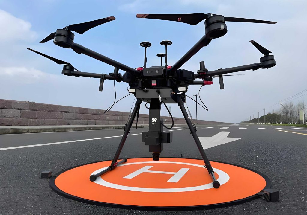
The operational workflow proceeds as follows: First, the remote control platform transmits mission commands to intelligent docking stations via 4G/5G networks. Upon receiving instructions, multiple UAV drones autonomously take off and proceed to their designated patrol areas following optimized flight paths. During mission execution, each UAV drone continuously streams real-time video and telemetry data back to the ground control station. After completing their assignments, the UAV drones automatically return to their docking stations, where battery charging and data offloading occur without human intervention.
3. Key Technological Innovations
3.1 UAV Drone Swarm Control Platform
The UAV drone swarm control platform I developed serves as the centralized management hub for all fleet operations. Built on the SSM (Spring+SpringMVC+MyBatis) framework, the platform offers high flexibility, low coupling, and excellent extensibility for future enhancements. Table 2 presents the core functional modules of the platform.
| Module | Sub-functions | Technical Implementation |
|---|---|---|
| Mission Planning | Waypoint editing, route upload, task scheduling | Visual map interface, one-click upload |
| Fleet Monitoring | Real-time trajectory, attitude parameters, battery status, GPS state | Multi-threaded data acquisition, Kafka+Storm processing |
| Command Dispatch | Takeoff, landing, hover, return-to-home, emergency stop | Remote instruction transmission via 4G/5G |
| Data Management | Video playback, image storage, flight log archiving | Distributed file system, database indexing |
| Intelligent Recognition | Anomaly detection, classification, alert generation | YOLOv11-EMA deep learning model |
The platform integrates seamlessly with multiple UAV drone models and docking station types, supporting unified configuration management across heterogeneous devices. Through its visual interface, operators can design flight missions by placing waypoints on an interactive map, adjusting parameters such as flight altitude, speed, and camera angle. The platform also incorporates dynamic re-planning capabilities, allowing real-time adjustment of flight paths in response to changing environmental conditions or mission requirements.
3.2 UAV Drone Swarm Cooperative Technologies
3.2.1 Flight Attitude Control
Precise attitude control is fundamental to stable and safe UAV drone swarm operations. The remote attitude control system I designed integrates GNSS modules, inertial measurement units (IMUs), power management units, flight attitude calculation engines, propulsion systems, and communication units. The flight control unit employs a high-performance chip as its core processor, executing real-time attitude estimation and control algorithms.
The dynamic model of a quadrotor UAV drone can be described using the body-fixed coordinate system. The angular velocity components are related to the Euler angle rates through the following projection:
$$
\begin{bmatrix}
p \\
q \\
r
\end{bmatrix}
=
\begin{bmatrix}
\dot{\phi} – \dot{\psi}\sin\theta \\
\dot{\theta}\cos\phi + \dot{\psi}\cos\theta\sin\phi \\
-\dot{\theta}\sin\phi + \dot{\psi}\cos\theta\cos\phi
\end{bmatrix}
$$
where $\phi$, $\theta$, and $\psi$ represent the roll, pitch, and yaw angles respectively, and $p$, $q$, $r$ are the corresponding angular velocity components in the body frame.
To achieve robust attitude estimation in the presence of sensor noise and disturbances, I implemented the Mahony complementary filter algorithm. This frequency-domain approach leverages the complementary noise characteristics of gyroscopes and accelerometers:
$$
\begin{aligned}
\dot{\hat{q}} &= \frac{1}{2} \hat{q} \otimes p(\bar{\Omega} + \delta) \\
\delta &= k_p e + k_i \int e \, dt \\
e &= \bar{v} \times \hat{v}
\end{aligned}
$$
where $\hat{q}$ represents the quaternion attitude estimate, $\bar{\Omega}$ denotes the measured angular velocity, $\delta$ is the PI controller output compensating for gyro drift, $e$ is the orientation error between measured and predicted inertial vectors, and $k_p$, $k_i$ are the proportional and integral gains respectively.
For attitude control, I adopted a dual-loop cascade PID structure with the outer loop regulating attitude angles and the inner loop controlling angular rates. The control law is formulated as:
$$
u(t) = K_p e(t) + K_i \int_0^t e(\tau) d\tau + K_d \frac{de(t)}{dt}
$$
where $K_p$, $K_i$, and $K_d$ are the proportional, integral, and derivative gains respectively, and $e(t)$ represents the error between desired and actual attitude. Table 3 summarizes the PID gain tuning parameters used in our system.
| Control Loop | Kp | Ki | Kd |
|---|---|---|---|
| Roll Outer Loop (Angle) | 4.5 | 0.02 | 0.12 |
| Roll Inner Loop (Angular Rate) | 0.35 | 0.005 | 0.01 |
| Pitch Outer Loop (Angle) | 4.5 | 0.02 | 0.12 |
| Pitch Inner Loop (Angular Rate) | 0.35 | 0.005 | 0.01 |
| Yaw Outer Loop (Angle) | 3.0 | 0.01 | 0.08 |
| Yaw Inner Loop (Angular Rate) | 0.25 | 0.003 | 0.008 |
3.2.2 Swarm Path Planning with Cooperative A* Algorithm
Path planning for UAV drone swarms presents unique challenges compared to single-platform scenarios, as the optimization objective shifts from individual path optimality to system-level coordination. Traditional A* algorithm excels at finding the shortest path for a single agent but fails to account for inter-agent coordination constraints. To address this limitation, I developed a cooperative A* algorithm specifically designed for multi-UAV drone swarm path planning.
The core innovation of the cooperative A* algorithm lies in its modified search strategy. Instead of selecting the node with the minimum cost function $f(n)$ from the Open set, the algorithm selects the node whose cost most closely matches a predetermined cooperative path length $F(n)$:
$$
\Delta f = F(n) – f(n)
$$
The search strategy selects the node minimizing $\Delta f$ for expansion:
$$
\min(\Delta f_1, \Delta f_2, \Delta f_3, \ldots, \Delta f_n) \rightarrow \text{NextPoint}
$$
where $F(n)$ represents the cooperative path length target and $f(n)$ is the estimated total path cost for the current node. This approach ensures that the final planned paths meet temporal coordination requirements, whether simultaneous arrival or sequential timing constraints.
The cooperative A* algorithm incorporates multiple constraint models including geographical environment constraints, obstacle avoidance constraints, and UAV drone performance limitations. Table 4 compares the performance of the cooperative A* algorithm against traditional approaches.
| Algorithm | Single Platform Optimality | Coordination Capability | Computational Complexity | Convergence Guarantee |
|---|---|---|---|---|
| Traditional A* | Yes | No | O(b^d) | Yes |
| Genetic Algorithm | Approximate | Partial | O(population * generations) | No |
| Particle Swarm Optimization | Approximate | Partial | O(particles * iterations) | No |
| Cooperative A* (Proposed) | Yes (per platform) | Yes | O(b^d * N) | Yes |
The algorithm first computes individually optimal paths for each UAV drone using standard A* search, then determines the maximum path length among all platforms as the cooperative target. A second search phase refines individual paths to match the cooperative target while respecting inter-platform separation constraints. This two-phase approach ensures both individual optimality and collective coordination.
3.2.3 Electronic Fence Management
To ensure operational safety and regulatory compliance, I implemented a comprehensive electronic fence management system for the UAV drone swarm. The system defines three categories of spatial zones:
| Zone Type | Definition | UAV Drone Behavior |
|---|---|---|
| Permitted Flight Zone | Areas where UAV drone operations are authorized | Normal mission execution |
| Restricted Zone | Areas requiring special permissions | Speed reduction, altitude limitation, hover on boundary |
| Prohibited Zone | Areas where UAV drone entry is forbidden | Immediate hover, alert trigger, automatic return |
The electronic fence database is dynamically maintained and synchronized across all UAV drone platforms in the swarm. When a UAV drone approaches a zone boundary, the system triggers preventive actions such as speed reduction or hover stabilization. In case of imminent prohibited zone incursion, the system executes emergency responses including automatic return-to-home or forced landing, ensuring failsafe operation even under communication loss.
3.3 Real-Time Performance Assurance for Swarm Monitoring
Real-time monitoring of multiple UAV drones operating simultaneously imposes stringent demands on data processing throughput and latency. Traditional batch processing architectures, which process status updates from each UAV drone sequentially in a single thread, cannot meet the millisecond-level response requirements of swarm operations.
To overcome this limitation, I designed a distributed processing architecture combining Apache Kafka for asynchronous message queuing with Apache Storm for stream processing. Table 6 compares the performance characteristics of different processing architectures.
| Architecture | Latency per Message | Throughput (messages/sec) | Scalability | Fault Tolerance |
|---|---|---|---|---|
| Single-threaded batch | ~120 ms | ~8 | Poor | None |
| Multi-threaded without queue | ~85 ms | ~25 | Moderate | Partial |
| Kafka + Storm (Proposed) | ~5 ms | ~200 | Excellent | Full |
The Kafka-based architecture partitions incoming status messages by UAV drone ID, ensuring that each drone’s data stream is processed independently and in parallel. The partition count is dynamically adjusted to match the number of active UAV drones in the swarm, maximizing throughput while maintaining message ordering guarantees. Storm topology processes the streaming data with sub-millisecond latency through a directed acyclic graph of spouts and bolts, enabling real-time computation of monitoring metrics, anomaly detection, and visualization updates.
3.4 5G-Based Communication Network for UAV Drone Swarms
Reliable, high-bandwidth communication is the backbone of effective UAV drone swarm operations. I developed a 5G-based multi-channel video transmission system that addresses the limitations of traditional UAV drone communication links, including range restrictions, signal interference, and bandwidth bottlenecks.
The system architecture employs a software-defined radio approach with the following key components:
Video Encoding and Transmission: The onboard camera captures real-time video streams, which are encoded using H.264 compression to balance quality and bandwidth efficiency. The encoded packets are transmitted via UDP protocol over 5G networks to minimize latency. The Real-Time Streaming Protocol (RTSP) is used to establish and control media sessions, enabling multi-terminal synchronization.
Streaming Server Infrastructure: The ground-side streaming server is built on the nginx + nginx-rtmp-module + ffmpeg stack. FFmpeg handles real-time transcoding and packetization, while nginx with RTMP module provides scalable streaming distribution to multiple clients simultaneously.
Multi-Channel Aggregation: The system supports aggregation of up to 16 concurrent video streams from different UAV drones, enabling operators to monitor the entire swarm’s visual feed from a single command center interface. Table 7 summarizes the video transmission performance metrics.
| Parameter | Traditional System | 5G-Based System (Proposed) |
|---|---|---|
| Maximum concurrent streams | 1 | 16 |
| End-to-end latency (5 km) | >5 seconds | <0.8 seconds |
| Video resolution | 1080p | 4K |
| Frame rate | 25 fps | 60 fps |
| Transmission range | Line-of-sight limited | Network-dependent |
| Packet loss rate | >5% | <0.1% |
3.5 Intelligent Anomaly Detection with YOLOv11-EMA
The ultimate goal of UAV drone swarm inspection is to automatically detect and classify anomalous features in the collected imagery. I developed an enhanced object detection model based on YOLOv11n, incorporating the Efficient Multi-scale Attention (EMA) module to improve recognition accuracy while maintaining computational efficiency.
Model Architecture: The YOLOv11n baseline introduces several architectural innovations including C3K2 modules, C2PSA attention mechanisms, and SPPF feature pyramids. Building on this foundation, I integrated the EMA module into the backbone network to enhance multi-scale feature representation.
The EMA module operates by first partitioning the input feature map along the channel dimension into groups, then applying parallel 1×1 and 3×3 convolution branches to capture contextual information at different scales. The outputs from all branches are fused to generate spatial attention weights:
$$
\text{EMA}(X) = \text{Concat}\left(\text{Conv}_{1\times1}(X_g), \text{Conv}_{3\times3}(X_g)\right) \otimes \sigma(W)
$$
where $X_g$ represents the grouped feature map, $W$ denotes learnable attention parameters, $\sigma$ is the sigmoid activation function, and $\otimes$ represents element-wise multiplication for attention re-weighting.
Training Dataset: I constructed a comprehensive dataset from real water conservancy UAV drone inspection missions, comprising 101,540 images with 140,300 annotated objects across six categories. Table 8 details the dataset composition.
| Category | Class Label | Number of Images | Number of Instances |
|---|---|---|---|
| Aggregated floating debris | g_garbage | 10,530 | 17,750 |
| Dispersed floating debris | d_garbage | 12,100 | 12,430 |
| Transport vessel | trans_boat | 14,050 | 33,910 |
| Construction spoil | spoil | 18,200 | 12,080 |
| Stagnant water accumulation | stag_water | 29,490 | 45,130 |
| Landslide/collapse | collapse | 17,170 | 19,000 |
Training Configuration: The model was trained for 90 epochs with a batch size of 8, using the Adam optimizer with initial learning rate of 1e-4 for the first 60 epochs, reduced to 1e-5 for the remaining 30 epochs. We employed two NVIDIA GTX 1080Ti GPUs with 11 GB memory each, running PyTorch 1.2.0 on Ubuntu 18.04.
Quantitative Results: I evaluated the proposed YOLOv11-EMA model against the baseline YOLOv11n and two attention-enhanced variants (SKNet-YOLOv11 and CBAM-YOLOv11). The evaluation metric is Average Precision (AP) at IoU threshold 0.5, along with mean Average Precision (mAP@0.5) across all categories.
| Category | YOLOv11n | SKNet-YOLOv11 | CBAM-YOLOv11 | YOLOv11-EMA (Proposed) |
|---|---|---|---|---|
| g_garbage | 61 | 76 | 68 | 92 |
| d_garbage | 60 | 76 | 71 | 91 |
| trans_boat | 61 | 78 | 74 | 93 |
| spoil | 56 | 83 | 70 | 81 |
| stag_water | 59 | 80 | 74 | 89 |
| collapse | 62 | 81 | 75 | 95 |
| mAP@0.5 | 59.83 | 79.00 | 72.00 | 90.17 |
The results demonstrate that the proposed YOLOv11-EMA model achieves a mAP@0.5 of 90.17%, representing improvements of 30.34 percentage points over the baseline YOLOv11n, 11.17 percentage points over SKNet-YOLOv11, and 18.17 percentage points over CBAM-YOLOv11. The EMA module’s ability to model multi-scale spatial context while maintaining computational efficiency is the key factor driving these performance gains. The IoU metric used for evaluation is defined as:
$$
\text{IoU} = \frac{\text{TP}}{\text{TP} + \text{FP} + \text{FN}}
$$
where TP represents true positive detections, FP represents false positives, and FN represents false negatives. The Average Precision for each category is computed by integrating the precision-recall curve:
$$
\text{AP} = \int_0^1 P(R) \, dR
$$
where $P(R)$ denotes precision as a function of recall. The mean Average Precision is simply the average of AP values across all categories:
$$
\text{mAP} = \frac{1}{C} \sum_{i=1}^{C} \text{AP}_i
$$
where $C$ is the number of categories (6 in our experiment).
4. Engineering Applications and Field Validation
I deployed and validated the UAV drone swarm networking system across multiple large-scale water conservancy projects, including the Datengxia Water Conservancy Project and the Nandu River Water Diversion Project. These field applications demonstrated significant improvements in inspection efficiency, data quality, and operational reliability.
4.1 Inspection Efficiency Enhancement
At the Datengxia Water Conservancy Project, the inspection area covers approximately 6 square kilometers of critical construction zones. Table 10 compares the performance of single-UAV drone operations versus the proposed swarm system.
| Metric | Single UAV Drone | Swarm System (2 UAV Drones) | Improvement Factor |
|---|---|---|---|
| Total inspection time (6 km²) | 12 hours | 2 hours | 6x |
| Area coverage per hour | 0.5 km² | 3.0 km² | 6x |
| Data acquisition efficiency | Single-channel | Multi-channel parallel | 16x (max) |
| Emergency response time | ~30 minutes | <5 minutes | 6x |
In July 2017, during a flood event that damaged a construction bridge at the Datengxia site, the UAV drone swarm system demonstrated its emergency response capability. The multi-platform coordinated search operation located the collapsed bridge structure in significantly less time than conventional methods, enabling rapid clearance of navigation channels and preventing further economic losses.
3.4 Multi-Channel Video Transmission Validation
I conducted comparative tests between the traditional UAV drone video transmission system and the proposed 5G-based multi-channel system. The results show that the proposed system achieves ultra-low latency of under 0.8 seconds within 5 kilometers range, compared to over 5 seconds for traditional systems sharing video to third-party platforms. The multi-channel aggregation capability enables simultaneous monitoring of up to 16 UAV drone video feeds without quality degradation or frame dropping.
4.3 High-Resolution Image Recognition Performance
In addition to real-time video analysis, the system processes high-resolution orthophoto mosaics for detailed infrastructure mapping. For a 6-square-kilometer area at the Aozhu Water Supply Project, I generated orthophoto mosaics with ground sampling distance of 5 cm. The deep convolutional neural network model achieved building extraction confidence of 0.944 and road extraction confidence of 0.904, demonstrating the system’s capability for automated infrastructure mapping and change detection.
By overlaying the extracted building footprints with shoreline management boundaries, the system automatically identifies illegal constructions within regulated zones through vector logical operations. This capability significantly reduces the manual effort required for compliance monitoring and enables proactive enforcement actions.
5. Conclusion
In this study, I have developed and validated a comprehensive UAV drone swarm networking system for intelligent water conservancy supervision. The system addresses the fundamental challenges of traditional inspection methods through an integrated approach encompassing task planning, flight control, communication, and intelligent image analysis.
The key contributions of this work can be summarized as follows:
First, I designed a cooperative A* path planning algorithm that enables multiple UAV drones to achieve coordinated mission execution while maintaining individual optimality. The algorithm incorporates temporal and spatial coordination constraints, ensuring simultaneous or sequential arrival at target locations while maintaining safe inter-platform separation.
Second, I implemented a dual-loop cascade PID control system enhanced with Mahony complementary filtering for robust attitude estimation and control. This system achieves stable flight performance even under adverse environmental conditions, providing the foundation for reliable swarm operations.
Third, I developed a distributed real-time monitoring architecture combining Kafka message queuing with Storm stream processing. This architecture achieves millisecond-level response times for concurrent status updates from multiple UAV drones, enabling operators to maintain full situational awareness of the entire swarm.
Fourth, I established a 5G-based multi-channel video transmission system that supports up to 16 concurrent high-definition video streams with sub-second latency. The system overcomes the range and bandwidth limitations of traditional UAV drone communication links, enabling effective remote operation and monitoring.
Fifth, I proposed the YOLOv11-EMA object detection model that achieves 90.17% mAP@0.5 on a challenging water conservancy anomaly detection dataset. The integration of the Efficient Multi-scale Attention module significantly improves detection accuracy while maintaining computational efficiency suitable for real-time deployment.
The system has been successfully deployed at multiple major water conservancy projects, demonstrating 6x improvement in inspection efficiency compared to single-UAV drone operations, along with enhanced detection accuracy and operational reliability. The “intelligent docking station + base station + control platform” architecture enables fully autonomous, unattended operations suitable for long-term continuous monitoring applications.
Future research directions include extending the system to handle heterogeneous UAV drone fleets with different sensor configurations, developing more sophisticated multi-agent coordination algorithms for dynamically changing mission requirements, and exploring edge computing approaches to reduce communication bandwidth requirements while improving real-time response capabilities at the swarm level.
The findings of this study provide both theoretical foundations and practical engineering solutions for advancing intelligent water conservancy management, demonstrating the transformative potential of UAV drone swarm technology for infrastructure monitoring and environmental surveillance applications.