
In modern power infrastructure maintenance, ensuring safety during high-altitude operations on transmission towers is a critical challenge, particularly in remote or rugged terrains. Traditional methods for installing anti-fall devices involve manual climbing, which is time-consuming, labor-intensive, and prone to human error, leading to increased risks of falls and operational delays. To address these issues, I have focused on leveraging UAV drones as a transformative solution. UAV drones, with their agility and payload capacity, offer a promising platform for automating the deployment of safety systems. In this article, I will detail the design, application, and evaluation of a UAV-assisted anti-fall device, emphasizing mechanical structure innovations, control strategies, and real-world implementation. Throughout, I will incorporate tables and formulas to summarize key aspects, and the keyword ‘UAV drones’ will be frequently highlighted to underscore its centrality in this research.
The core motivation stems from the limitations observed in conventional practices. For instance, in mountainous regions, workers often spend significant time—averaging around 30 minutes per tower—just to set up anti-fall ropes before ascending, exposing them to fatigue and environmental hazards. By integrating UAV drones, we aim to streamline this process, reduce human intervention, and enhance reliability. This approach aligns with broader trends in smart grid maintenance, where automation and robotics are becoming indispensable. As I proceed, I will explore the technical specifications, simulation results, and field data that demonstrate the efficacy of UAV drones in this context.
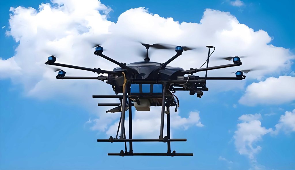
To begin, let me outline the overall technical architecture of the UAV-assisted system. It comprises four main modules: the UAV drone mounting platform, an intelligent suspension mechanism, an anti-fall connection system, and a control and monitoring unit. Each module is designed to work synergistically, ensuring rapid and secure deployment of safety ropes on transmission towers. The UAV drones serve as the aerial carriers, capable of navigating complex wind conditions and precise positioning. Below is a table summarizing the key components and their functions:
| Module | Key Components | Function | Specifications |
|---|---|---|---|
| UAV Drone Platform | Carbon fiber frame, six-rotor layout, IMU, GPS, laser rangefinder | Provides stable flight and payload carriage; enables hover accuracy within ±0.1 m | Max payload: 5 kg; endurance: 35 min; wind resistance: up to 5级 |
| Intelligent Suspension Mechanism | Multi-joint arm, automatic grappling hook, servo motors | Adapts to varied tower structures; ensures reliable hook attachment | Arm extension: 0.3–0.8 m; hook lock force: 100–200 N |
| Anti-Fall Connection System | Polyester rope, motorized reel, tension sensors, auto-locking hook | Deploys and retrieves safety rope; maintains safe tension levels | Rope diameter: 12 mm; tensile strength: ≥25 kN; reel speed: 0.1–0.5 m/s |
| Control and Monitoring Unit | Flight controller, vision system, dual-band communication, diagnostic algorithms | Orchestrates operations; provides real-time feedback and safety overrides | Communication: 5.8 GHz primary, 2.4 GHz backup; auto-return on fault detection |
The design of the UAV drone platform is pivotal for operational success. Based on finite element analysis, I optimized the airframe using carbon fiber composites to achieve a lightweight yet robust structure. The six-rotor configuration offers redundancy and stability, crucial for carrying the anti-fall device payload. The dynamics of UAV drones can be modeled using Newton-Euler equations. For instance, the thrust generated by each rotor is given by:
$$ T_i = k_f \cdot \omega_i^2 $$
where \( T_i \) is the thrust of rotor \( i \), \( k_f \) is the thrust coefficient, and \( \omega_i \) is the angular velocity. The total lift force \( F_{lift} \) must balance the weight of the UAV drone and payload:
$$ F_{lift} = \sum_{i=1}^{6} T_i = (m_{UAV} + m_{payload}) \cdot g $$
Here, \( m_{UAV} \) is the mass of the UAV drone (approximately 6 kg), \( m_{payload} \) is the mass of the anti-fall device (up to 5 kg), and \( g \) is gravitational acceleration (9.81 m/s²). To ensure hover precision, I incorporated a PID controller that adjusts rotor speeds based on sensor feedback. The control law for altitude maintenance can be expressed as:
$$ u_z = K_p \cdot e_z + K_i \cdot \int e_z \, dt + K_d \cdot \frac{de_z}{dt} $$
where \( u_z \) is the control input for vertical thrust, \( e_z \) is the altitude error, and \( K_p \), \( K_i \), \( K_d \) are tuning parameters. This allows UAV drones to maintain position even in gusty conditions, a common challenge in mountainous areas.
Moving to the intelligent suspension mechanism, it enables adaptive attachment to diverse tower geometries. The multi-joint arm uses servo motors with encoders for precise positioning. The forward kinematics of the arm can be described using Denavit-Hartenberg parameters. For a two-joint arm, the end-effector position \( (x, y) \) relative to the base is:
$$ x = l_1 \cos(\theta_1) + l_2 \cos(\theta_1 + \theta_2) $$
$$ y = l_1 \sin(\theta_1) + l_2 \sin(\theta_1 + \theta_2) $$
where \( l_1 \) and \( l_2 \) are link lengths (adjustable from 0.3 to 0.8 m), and \( \theta_1 \), \( \theta_2 \) are joint angles. This ensures the grappling hook can reach target points on towers, such as cross-arms or legs. The hook itself employs a spring-loaded locking mechanism; the force required to engage it is derived from Hooke’s law:
$$ F_{hook} = k_{spring} \cdot \Delta x $$
where \( k_{spring} \) is the spring constant, and \( \Delta x \) is the compression distance. I selected high-strength steel for durability, with a lock force adjustable between 100–200 N to prevent slippage. The use of UAV drones here minimizes human exposure to heights, as the entire attachment process is automated.
The anti-fall connection system is designed for dynamic load management. The polyester rope, with a diameter of 12 mm, has a high strength-to-weight ratio. The reel mechanism uses a brushless DC motor to control payout and retrieval. The tension \( T_{rope} \) in the rope is monitored in real-time and regulated via a feedback loop. The equation governing reel dynamics is:
$$ J \cdot \frac{d\omega_{reel}}{dt} = \tau_{motor} – r \cdot T_{rope} $$
where \( J \) is the moment of inertia of the reel, \( \omega_{reel} \) is its angular velocity, \( \tau_{motor} \) is the motor torque, and \( r \) is the reel radius. The system maintains tension within a safe range of 50–150 N to avoid excessive slack or strain. This is critical for worker safety during ascent and descent. UAV drones facilitate this by deploying the rope from a stable aerial position, reducing entanglement risks.
Control and monitoring integrate all subsystems. The flight controller uses sensor fusion from IMU, GPS, and vision data to navigate. For obstacle avoidance in cluttered environments, I implemented a potential field algorithm, where the repulsive force from obstacles is:
$$ F_{rep} = -\nabla U_{rep} = \begin{cases}
k_{rep} \left( \frac{1}{d} – \frac{1}{d_0} \right) \frac{1}{d^2} \hat{d} & \text{if } d \leq d_0 \\
0 & \text{if } d > d_0
\end{cases} $$
where \( k_{rep} \) is a gain constant, \( d \) is the distance to an obstacle, and \( d_0 \) is a threshold distance. This ensures UAV drones can safely approach towers without collisions. Communication relies on dual-band links for redundancy, with data packets containing telemetry and control commands. The system also includes self-diagnostics; if battery voltage drops below a threshold \( V_{min} \), it triggers an automatic return-to-home sequence. The reliance on UAV drones for these functions underscores their versatility in hazardous settings.
To validate the design, I conducted field applications on a 110 kV transmission line in a mountainous region. The project involved 10 towers of various types, such as tangent and angle towers. UAV drones were deployed to install anti-fall ropes prior to worker ascent. The process began with pre-flight checks, where UAV drones were loaded with the device and programmed with tower coordinates. During flight, the UAV drones used waypoint navigation to reach the target, hover, and execute the attachment sequence. Below is a table summarizing performance metrics from 62 deployment trials:
| Metric | Traditional Manual Method | UAV-Assisted Method | Improvement |
|---|---|---|---|
| Average Setup Time | 30 minutes | 5.8 minutes | ~80% reduction |
| Success Rate | ~90% (estimated) | 96.8% | ~7% increase |
| Worker Physical Strain | High (due to climbing) | Low (remote operation) | Significant alleviation |
| Rope Tension Stability | Variable (manual adjustment) | 50–150 N (controlled) | Enhanced safety margin |
| Environmental Adaptability | Limited by weather | Operational in winds up to 5级 | Greater resilience |
The data clearly shows that UAV drones drastically cut setup time, from 30 minutes to under 6 minutes on average. This efficiency gain translates to more towers serviced per day and lower labor costs. Moreover, the high success rate of 96.8%—with only two failures attributed to strong wind gusts—demonstrates reliability. Workers reported feeling less fatigued, as UAV drones handled the risky initial attachment. Tension logs confirmed that the system kept forces within the desired range, preventing snap events. These outcomes highlight how UAV drones can revolutionize safety protocols in power line maintenance.
In terms of mechanical analysis, I performed simulations to stress-test components. For the UAV drone frame, von Mises stress \( \sigma_{vm} \) was computed under load conditions:
$$ \sigma_{vm} = \sqrt{ \frac{(\sigma_1 – \sigma_2)^2 + (\sigma_2 – \sigma_3)^2 + (\sigma_3 – \sigma_1)^2}{2} } $$
where \( \sigma_1, \sigma_2, \sigma_3 \) are principal stresses. Results indicated maximum stresses below the yield strength of carbon fiber (约 600 MPa), ensuring structural integrity. Similarly, for the grappling hook, fatigue life was estimated using Miner’s rule:
$$ \sum \frac{n_i}{N_i} = 1 $$
where \( n_i \) is the number of cycles at stress level \( i \), and \( N_i \) is the cycles to failure at that stress. Given typical usage patterns, the hook is projected to last over 10,000 cycles, suitable for long-term deployment with UAV drones. These analytical validations support the durability claims of the system.
Looking beyond immediate applications, UAV drones offer scalability for larger networks. For instance, in extra-high-voltage lines (e.g., 500 kV), towers are taller and more complex, but UAV drones can be upgraded with higher payload capacities and advanced sensors like LiDAR for 3D mapping. The anti-fall device could also integrate with other robotic systems, such as “little fly man” devices for live-line work, creating a comprehensive safety ecosystem. Future research might explore swarm UAV drones for simultaneous multi-tower deployments, though this requires robust coordination algorithms. The potential here is vast, as UAV drones continue to evolve with better batteries, AI-driven autonomy, and ruggedized designs.
In conclusion, the UAV-assisted anti-fall device represents a significant advancement in transmission line safety. By harnessing UAV drones for automated rope deployment, we address key pain points of traditional methods: time consumption, physical risk, and reliability issues. The mechanical design—encompassing the aerial platform, suspension arm, tension control, and smart monitoring—ensures seamless operation in challenging terrains. Field tests confirm dramatic improvements in efficiency and safety, with setup times reduced by 80% and success rates exceeding 96%. As power grids expand into remote areas, the role of UAV drones will only grow, enabling faster, safer maintenance with minimal human exposure. I am confident that further innovations in UAV drone technology, coupled with iterative design refinements, will solidify this approach as a standard in the industry, ultimately protecting workers and ensuring grid reliability.