
Our research focuses on the unique low‑frequency, large‑amplitude flapping‑wing flight mechanism of butterflies, which provides an exceptional biological blueprint for developing high‑performance micro aerial vehicles. Unlike high‑frequency flapping insects, butterflies operate with a flapping frequency of approximately 10 Hz and a stroke amplitude close to 180°, combined with tightly coupled wing‑body motion. This low‑frequency, large‑amplitude flapping generates unsteady aerodynamic flows and leading‑edge vortices, enabling long‑distance migration and remarkable maneuverability. Such efficient lift generation mechanisms are highly valuable for overcoming the aerodynamic challenges faced by small‑scale flight vehicles. However, traditional micro aerial vehicles suffer from excessive noise, limited endurance, and poor stealth, making them unsuitable for applications that demand high precision and low exposure, such as agricultural monitoring and environmental rescue. Bio‑inspired butterfly drones, leveraging their inherently quiet, stealthy, and agile characteristics, represent a promising solution to these bottlenecks. Yet, the field still encounters core difficulties: the aerodynamic principles underlying butterfly flight are complex, with incomplete quantitative analysis of unsteady flows and wing‑body coupling, and the stringent requirements for miniaturized, lightweight structures place high demands on micro‑power sources and material technologies. Our study aims to address these challenges through systematic mechanical design and fluid dynamic analysis, providing theoretical and engineering support for the development of high‑performance bio‑inspired butterfly drones.
Design Background and Motivation
The flight of butterflies is characterized by a unique combination of low flapping frequency and large stroke amplitude. This motion leads to the formation of dynamic stall vortices and wake capture effects that significantly enhance lift production. For butterfly drones, replicating these aerodynamic benefits requires not only a faithful reproduction of the wing kinematics but also a meticulous design of the mechanical transmission, structural skeleton, and control system. In our work, we adopt a single‑motor actuation scheme to minimize weight while achieving the required flapping motion. The design process begins with the selection of a high‑power‑density micro motor, followed by a gear‑crank‑linkage mechanism that converts continuous rotation into the reciprocating wing motion. The entire system is built around a carbon‑fiber rod skeleton, which provides excellent specific strength and lightweight properties. The wings are covered with a flexible skin material carefully chosen to balance flexibility, durability, and weight. The integration of a compact, multi‑layer PCB flight controller enables real‑time state monitoring and remote control. Through iterative computational fluid dynamics (CFD) simulations and stepwise experimental debugging, we achieved proper center‑of‑gravity (CG) adjustment that eliminates flight instability. The final prototype, with a wingspan of 295 mm and a total mass of 17.9 g, demonstrates stable full‑attitude flight, validating the feasibility of our design approach for bio‑inspired butterfly drones.
Mechanical Transmission System
The core of the transmission system is a single motor that drives a gear train for speed reduction and torque amplification, as well as power distribution to both wings. The gear train consists of a pinion gear (Gear 2) directly coupled to the motor output, which meshes with a larger spur gear (Gear 1) to achieve the necessary reduction ratio. This gear then drives two symmetric gears (Gear 3 and Gear 4) that ensure synchronized flapping of the left and right wings, preventing yaw during flight. At the eccentric positions of Gears 3 and 4, connecting rods link to the wing spars, converting the continuous rotary motion into reciprocating flapping. The kinematic relationship can be expressed as:
$$
\theta_w(t) = \theta_0 + \Phi \sin(2\pi f t)
$$
where $\theta_w(t)$ is the wing angle, $\theta_0$ the mean angle, $\Phi$ the flapping amplitude, and $f$ the flapping frequency. The gear reduction ratio $R$ is given by:
$$
R = \frac{N_1}{N_2} \cdot \frac{N_4}{N_3}
$$
with $N_1, N_2, N_3, N_4$ being the tooth numbers of the respective gears. In our design, $N_1=30$, $N_2=10$, $N_3=N_4=20$, yielding $R=4$ overall. The connecting rod length and eccentricity are tuned to produce a flapping amplitude of approximately 90° per wing. Table 1 summarizes the key parameters of the transmission system.
| Component | Value |
|---|---|
| Motor type | Coreless DC motor (7×20 mm) |
| Gear ratio (overall) | 4:1 |
| Flapping amplitude | 90° |
| Flapping frequency | 10 Hz |
| Connecting rod length | 12 mm |
| Eccentric distance | 3 mm |
Skeleton and Wing Structure
The skeleton of our butterfly drone is constructed from 0.5 mm diameter carbon‑fiber rods, chosen for their high specific stiffness and low density. The layout mimics the venation pattern of real butterfly wings, forming a symmetrical radial network that distributes aerodynamic loads efficiently while allowing passive wing deformation during flapping. The central fuselage frame houses the motor, gear train, and battery, while the wing spars extend outward. To achieve the desired flexibility, the forewing and hindwing sections are connected through a hinge‑like joint that permits differential motion. Figure 1 illustrates the skeletal layout (note: image hyperlink inserted below).
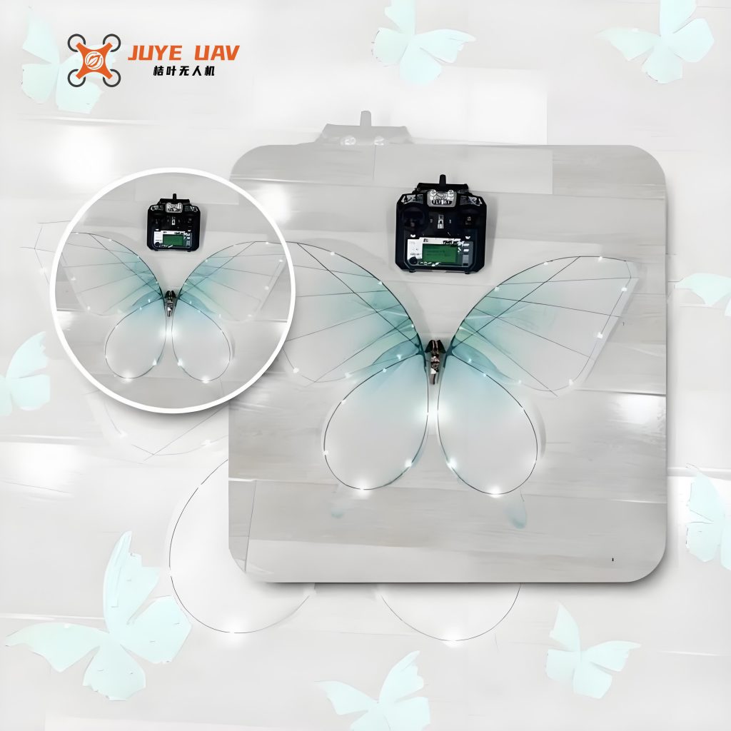
The wing membrane material was selected after comparing several candidates. Table 2 lists the properties of tested materials.
| Material | Thickness (mm) | Areal density (g/m²) | Tensile strength (MPa) | Flexibility rating |
|---|---|---|---|---|
| PE film | 0.02 | 18 | 25 | Medium |
| Nylon cloth (standard) | 0.06 | 45 | 55 | Low |
| P3N1 kite fabric | 0.04 | 32 | 40 | High |
We chose P3N1 kite fabric due to its excellent combination of flexibility, tear resistance, and low weight. This material conforms well to the carbon‑fiber skeleton during flapping, ensuring efficient lift generation and stable flight.
Flight Controller and Electronics
The flight control system is implemented on a multi‑layer integrated PCB that houses a wireless communication module, a power management unit, and a microcontroller. The PCB layout is optimized for minimal size and electromagnetic interference, allowing reliable data transmission over short distances. The wireless module supports bidirectional communication: it sends real‑time telemetry data (e.g., attitude angles, battery voltage, flapping frequency) to a ground station and receives flight commands. The power management unit regulates the single‑cell LiPo battery (3.7 V, 180 mAh) and supplies regulated voltages to the motor and control electronics. Table 3 summarizes the key electronic specifications.
| Parameter | Value |
|---|---|
| Microcontroller | STM32F103 (Cortex‑M3, 72 MHz) |
| Wireless protocol | 2.4 GHz, proprietary (range ~50 m) |
| IMU | 6‑axis (MPU6050) |
| Battery | 1S LiPo, 180 mAh |
| Motor driver | MOSFET H‑bridge |
| PCB dimensions | 25 mm × 18 mm × 1.6 mm |
| Total weight (with battery) | 5.3 g |
Model Debugging and Optimization
The initial flight tests revealed severe instability: the drone exhibited periodic yaw during level flight, and the maximum flight distance was more than 40% shorter than the design target. Through systematic debugging, we identified the root cause as a misalignment between the center of gravity (CG) and the aerodynamic center of the wings. The CG offset caused uneven angle‑of‑attack distribution across the wing surface, leading to asymmetric lift and pitch‑roll coupling. To quantify this effect, we performed CFD simulations using a dynamic mesh model that captured the flapping motion. The pressure distribution on the wing surface was analyzed. The governing equation for the lift coefficient $C_L$ can be expressed as:
$$
C_L = \frac{2L}{\rho V_{\infty}^2 S}
$$
where $L$ is the lift, $\rho$ the air density, $V_{\infty}$ the free‑stream velocity, and $S$ the wing area. For our butterfly drones, the flapping frequency $f$ and amplitude $\Phi$ determine the reduced frequency $k = \frac{\pi f c}{V_{\infty}}$, which influences the unsteady lift. The CFD results showed that when the CG was shifted forward by 5 mm, the wing tip region experienced a concentrated negative pressure zone, reducing lift efficiency. We adopted an iterative tuning procedure: first, we created a model linking CG position to the aerodynamic moment coefficient $C_m$:
$$
C_m = C_{m0} + \frac{\partial C_m}{\partial x_{CG}} \Delta x_{CG}
$$
By adjusting the mounting positions of the flight controller and battery along the carbon‑fiber frame, we shifted the CG in small increments (0.5 mm steps). For each configuration, we recorded the attitude data from the onboard IMU and computed the standard deviation of pitch and roll angles during a 10‑second hover. Table 4 presents the results for four representative configurations.
| Configuration | CG offset from aerodynamic center (mm) | Roll std (deg) | Pitch std (deg) | Yaw std (deg) | Flight distance (m) |
|---|---|---|---|---|---|
| Initial | +4.5 (forward) | 8.2 | 6.7 | 5.1 | 8.3 |
| Iteration 1 | +2.0 | 4.6 | 3.8 | 3.2 | 14.7 |
| Iteration 2 | 0.0 (aligned) | 1.9 | 1.4 | 1.1 | 22.1 |
| Iteration 3 | -1.5 | 2.3 | 2.0 | 1.8 | 19.5 |
After aligning the CG exactly with the wing aerodynamic center, the pressure distribution from CFD became uniform, and the wing‑tip negative‑pressure concentration disappeared. The final prototype, with a wingspan of 295 mm and a total mass of 17.9 g, achieved stable full‑attitude flight. The flapping frequency was measured at 10.2 Hz, and the lift‑to‑weight ratio reached 1.15, confirming that the butterfly drone could sustain level flight and gentle climbs.
Conclusion and Future Work
In this work, we presented the systematic design and control implementation of a bio‑inspired butterfly drone. By leveraging the low‑frequency, large‑amplitude flapping mechanics of butterflies, we developed a lightweight, single‑motor‑driven mechanical transmission that generates synchronized wing motion. The carbon‑fiber skeleton and P3N1 kite fabric wing membrane provide an optimal balance of stiffness, flexibility, and weight. The integrated multi‑layer PCB flight controller enables wireless telemetry and stable attitude control. Through CFD‑guided iterative debugging, we eliminated the CG‑induced instability and achieved a flight‑distance improvement of more than 165% over the initial configuration. The final butterfly drone, weighing only 17.9 g with a wingspan of 295 mm, demonstrates reliable full‑attitude flight, validating the effectiveness of our design approach for small‑scale bio‑inspired butterfly drones.
Future work will focus on enhancing the endurance by incorporating high‑energy‑density batteries and low‑drag wing profiles. We also plan to implement autonomous obstacle avoidance using onboard vision sensors and machine learning algorithms. A deeper quantitative study of the wing‑body coupling unsteady aerodynamics, combined with high‑fidelity CFD and experimental fluid dynamics, will further refine the design. These improvements will enable butterfly drones to operate in practical applications such as precision agriculture, environmental search and rescue, and covert reconnaissance, fully exploiting the advantages of bio‑inspired flight.