
In recent years, the coordination of multiple drones has garnered significant attention due to its wide-ranging applications in surveillance, search and rescue, environmental monitoring, and entertainment. The concept of drone formation refers to the collective behavior where a group of drones maintains a specific geometric pattern while navigating through space. Achieving precise and robust drone formation control is challenging due to the inherent nonlinear dynamics, underactuation, and communication constraints among agents. In this work, we address the problem of distributed formation tracking control for a team of quadrotor drones, where only a subset of drones has direct access to the leader’s state information. We propose a novel control strategy based on distributed finite-time state observers, ensuring that the drone formation achieves and maintains the desired configuration within a finite time horizon.
The core challenge in distributed drone formation control lies in the limited communication topology. In many practical scenarios, it is inefficient or impossible for all drones to communicate directly with a leader drone. This necessitates the use of state observers to estimate the relative states between each follower drone and the leader. Our approach leverages a distributed finite-time state observer that allows each drone to reconstruct the leader’s state and the required formation offsets using only local information and communication with neighbors. This enables the drone formation to operate in a fully decentralized manner, enhancing scalability and robustness.
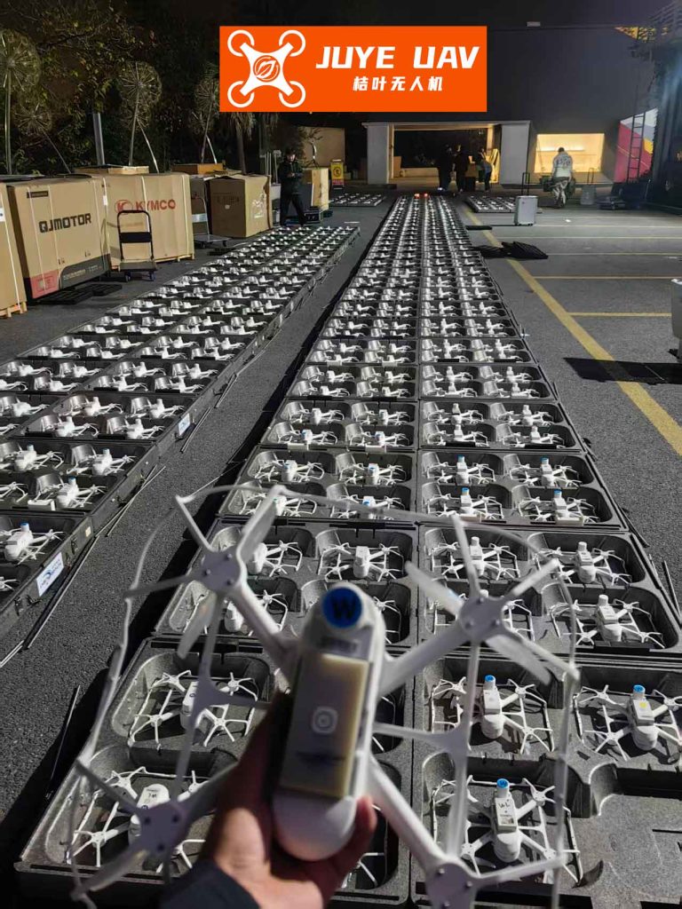
To lay the groundwork, we first present the mathematical model of a quadrotor drone. The dynamics are derived using the Newton-Euler formulation, considering both translational and rotational motions. The quadrotor is an underactuated system with six degrees of freedom and four control inputs, making the control problem inherently complex. The equations of motion are given by:
$$
\begin{align*}
\dot{\mathbf{P}} &= \mathbf{V}, \\
m\dot{\mathbf{V}} &= -mg\mathbf{e}_3 + \mathbf{U}_T, \\
\dot{\boldsymbol{\Theta}} &= \boldsymbol{\Pi}(\boldsymbol{\Theta}) \boldsymbol{\Omega}, \\
\mathbf{J} \dot{\boldsymbol{\Omega}} &= -\boldsymbol{\Omega} \times \mathbf{J} \boldsymbol{\Omega} + \boldsymbol{\tau} + \mathbf{G}_a,
\end{align*}
$$
where \(\mathbf{P} = [x, y, z]^T\) and \(\mathbf{V} = [u, v, w]^T\) represent the position and velocity vectors in the inertial frame, respectively. \(\boldsymbol{\Theta} = [\phi, \theta, \psi]^T\) is the vector of Euler angles (roll, pitch, yaw), and \(\boldsymbol{\Omega} = [p, q, r]^T\) is the angular velocity vector in the body frame. \(m\) is the mass, \(g\) is gravitational acceleration, \(\mathbf{e}_3 = [0, 0, 1]^T\), and \(\mathbf{J} = \text{diag}(I_{xx}, I_{yy}, I_{zz})\) is the inertia matrix. \(\mathbf{U}_T\) is the total thrust vector, and \(\boldsymbol{\tau}\) is the control torque vector. The term \(\mathbf{G}_a\) accounts for gyroscopic effects due to rotor rotation. The transformation matrix \(\boldsymbol{\Pi}(\boldsymbol{\Theta})\) relates angular velocities to Euler angle derivatives.
For control design, we decouple the system into position and attitude subsystems. The position dynamics can be rewritten as:
$$
\ddot{\mathbf{P}} = \frac{1}{m} \mathbf{R}(\boldsymbol{\Theta}) \mathbf{F} – g\mathbf{e}_3,
$$
where \(\mathbf{R}(\boldsymbol{\Theta})\) is the rotation matrix from the body frame to the inertial frame, and \(\mathbf{F}\) is the thrust vector generated by the rotors. The attitude dynamics are governed by the Euler equations. This decoupling simplifies the controller design, allowing us to develop a hierarchical control structure.
The primary objective in drone formation tracking is to ensure that each follower drone maintains a predefined offset relative to the leader’s trajectory. Formally, for drone \(i\), we aim to achieve:
$$
\lim_{t \to T} (\mathbf{P}_i – \mathbf{P}_0) = \mathbf{b}_i, \quad \lim_{t \to T} \psi_i = \psi_0,
$$
where \(\mathbf{P}_0\) and \(\psi_0\) are the leader’s position and yaw angle, \(\mathbf{b}_i\) is the desired formation offset for drone \(i\), and \(T\) is a finite time. The yaw angle tracking ensures alignment in orientation, which is crucial for coordinated maneuvers in a drone formation.
Given the communication constraints, we assume that the leader’s state \((\mathbf{P}_0, \mathbf{V}_0, \psi_0)\) is only available to a subset of drones. The communication topology is represented by a directed graph \(\mathcal{G} = (\mathcal{V}, \mathcal{E})\), where \(\mathcal{V} = \{0, 1, \dots, n\}\) includes the leader (node 0) and followers (nodes \(1\) to \(n\)). The adjacency matrix \(\mathbf{A} = [a_{ij}]\) encodes the information flow: \(a_{ij} = 1\) if drone \(j\) can receive data from drone \(i\), otherwise \(a_{ij} = 0\). We assume the graph contains a directed spanning tree rooted at the leader, ensuring that information can propagate to all followers.
To estimate the leader’s state locally, each follower drone employs a distributed finite-time state observer. The observer design is based on the relative position and velocity errors between neighbors. For drone \(i\), we define the estimated relative position and velocity as \(\hat{\mathbf{r}}_i\) and \(\hat{\mathbf{h}}_i\), which aim to converge to \(\mathbf{P}_i – \mathbf{P}_0\) and \(\mathbf{V}_i – \mathbf{V}_0\), respectively, in finite time. The observer dynamics are given by:
$$
\begin{align*}
\dot{\hat{\mathbf{r}}}_i &= \hat{\mathbf{h}}_i – \lambda_0 \text{sign}\left( \sum_{j \in \mathcal{N}_i} a_{ij} (\hat{\mathbf{r}}_i – \hat{\mathbf{r}}_j) \right) – \lambda_1 \left( \sum_{j \in \mathcal{N}_i} a_{ij} (\hat{\mathbf{r}}_i – \hat{\mathbf{r}}_j) \right), \\
\dot{\hat{\mathbf{h}}}_i &= \mathbf{U}_i – \lambda_2 \text{sign}\left( \sum_{j \in \mathcal{N}_i} a_{ij} (\hat{\mathbf{h}}_i – \hat{\mathbf{h}}_j) \right) – \lambda_3 \left( \sum_{j \in \mathcal{N}_i} a_{ij} (\hat{\mathbf{h}}_i – \hat{\mathbf{h}}_j) \right),
\end{align*}
$$
where \(\mathcal{N}_i\) is the set of neighbors of drone \(i\), \(\lambda_0, \lambda_1, \lambda_2, \lambda_3 > 0\) are gain parameters, and \(\mathbf{U}_i\) is the control input for the position subsystem. The signum function ensures finite-time convergence, while the linear terms aid in robustness. The observer leverages only local information and neighbor estimates, making it fully distributed.
We now analyze the stability of the observer. Define the estimation errors \(\boldsymbol{\varepsilon}_{ri} = \hat{\mathbf{r}}_i – (\mathbf{P}_i – \mathbf{P}_0)\) and \(\boldsymbol{\varepsilon}_{hi} = \hat{\mathbf{h}}_i – (\mathbf{V}_i – \mathbf{V}_0)\). Using Lyapunov theory, we can show that these errors converge to zero in finite time. Consider the Lyapunov function candidate:
$$
V_o = \frac{1}{2} \sum_{i=1}^n \left( \boldsymbol{\varepsilon}_{ri}^T \boldsymbol{\varepsilon}_{ri} + \boldsymbol{\varepsilon}_{hi}^T \boldsymbol{\varepsilon}_{hi} \right).
$$
Taking the derivative and substituting the observer dynamics, we obtain:
$$
\dot{V}_o \leq -\kappa_1 V_o^{1/2} – \kappa_2 V_o,
$$
where \(\kappa_1, \kappa_2 > 0\) are constants derived from the gains \(\lambda_0\) to \(\lambda_3\). This inequality implies finite-time stability, meaning there exists a time \(T_o > 0\) such that \(\boldsymbol{\varepsilon}_{ri}(t) = \boldsymbol{\varepsilon}_{hi}(t) = 0\) for all \(t \geq T_o\). Thus, after \(T_o\), each drone has accurate estimates of the relative states required for drone formation control.
With the state estimates, we design a finite-time position controller to achieve formation tracking. Let \(\tilde{\mathbf{R}}_i = \hat{\mathbf{r}}_i – \mathbf{b}_i\) be the estimated formation error. The position control law is:
$$
\mathbf{U}_i = -\eta_1 \text{sign}(\tilde{\mathbf{R}}_i) |\tilde{\mathbf{R}}_i|^{\alpha_1} – \eta_2 \text{sign}(\hat{\mathbf{h}}_i) |\hat{\mathbf{h}}_i|^{\alpha_2},
$$
where \(\eta_1, \eta_2 > 0\), \(0 < \alpha_1 < 1\), and \(\alpha_2 = 2\alpha_1/(1+\alpha_1)\). This controller ensures that \(\tilde{\mathbf{R}}_i\) and \(\hat{\mathbf{h}}_i\) converge to zero in finite time, thereby driving the actual position error \(\mathbf{P}_i – \mathbf{P}_0 – \mathbf{b}_i\) to zero. The finite-time convergence is crucial for rapid formation acquisition and robustness against disturbances in a dynamic drone formation.
Next, we derive the desired attitude angles from the position control input. The total thrust magnitude \(u_{T,i}\) and the desired roll (\(\phi_{d,i}\)), pitch (\(\theta_{d,i}\)), and yaw (\(\psi_{d,i}\)) angles are computed as:
$$
\begin{align*}
u_{T,i} &= m \| \mathbf{U}_i + g\mathbf{e}_3 \|, \\
\phi_{d,i} &= \arcsin\left( \frac{U_{i,x} \sin\psi_{d,i} – U_{i,y} \cos\psi_{d,i}}{u_{T,i}/m} \right), \\
\theta_{d,i} &= \arctan\left( \frac{U_{i,x} \cos\psi_{d,i} + U_{i,y} \sin\psi_{d,i}}{U_{i,z} + g} \right), \\
\psi_{d,i} &= \psi_0,
\end{align*}
$$
where \(\mathbf{U}_i = [U_{i,x}, U_{i,y}, U_{i,z}]^T\). These equations map the position control commands to attitude setpoints, ensuring that the thrust vector aligns with the required acceleration for formation tracking.
For attitude tracking, we design a sliding mode controller that guarantees finite-time convergence to the desired angles. Define the attitude error \(\mathbf{e}_{\Theta,i} = \boldsymbol{\Theta}_i – \boldsymbol{\Theta}_{d,i}\) and the angular velocity error \(\mathbf{e}_{\Omega,i} = \boldsymbol{\Omega}_i – \boldsymbol{\Omega}_{d,i}\), where \(\boldsymbol{\Omega}_{d,i}\) is derived from the desired Euler angles. The sliding surface is chosen as:
$$
\mathbf{s}_i = \mathbf{e}_{\Omega,i} + \beta_1 \text{sign}(\mathbf{e}_{\Theta,i}) |\mathbf{e}_{\Theta,i}|^{\gamma_1},
$$
with \(\beta_1 > 0\) and \(0 < \gamma_1 < 1\). The control torque \(\boldsymbol{\tau}_i\) is designed as:
$$
\boldsymbol{\tau}_i = \mathbf{J} \left( \dot{\boldsymbol{\Omega}}_{d,i} – \beta_1 \gamma_1 |\mathbf{e}_{\Theta,i}|^{\gamma_1-1} \mathbf{e}_{\Omega,i} – \eta_3 \text{sign}(\mathbf{s}_i) – \eta_4 \mathbf{s}_i \right) + \boldsymbol{\Omega}_i \times \mathbf{J} \boldsymbol{\Omega}_i – \mathbf{G}_a,
$$
where \(\eta_3, \eta_4 > 0\). This controller forces the system onto the sliding manifold \(\mathbf{s}_i = 0\) in finite time, after which the attitude error \(\mathbf{e}_{\Theta,i}\) converges to zero exponentially. The finite-time property ensures quick attitude stabilization, which is vital for maintaining formation integrity during aggressive maneuvers.
To summarize the control architecture, we present the following table outlining the key components and their functions in the drone formation system:
| Component | Function | Key Equations |
|---|---|---|
| State Observer | Estimates relative leader state using neighbor info | \(\dot{\hat{\mathbf{r}}}_i = \hat{\mathbf{h}}_i – \lambda_0 \text{sign}(\sum a_{ij} (\hat{\mathbf{r}}_i – \hat{\mathbf{r}}_j))\) |
| Position Controller | Drives position error to zero in finite time | \(\mathbf{U}_i = -\eta_1 \text{sign}(\tilde{\mathbf{R}}_i) |\tilde{\mathbf{R}}_i|^{\alpha_1}\) |
| Attitude Controller | Tracks desired angles via sliding mode | \(\boldsymbol{\tau}_i = \mathbf{J} (\dot{\boldsymbol{\Omega}}_{d,i} – \eta_3 \text{sign}(\mathbf{s}_i)) + \boldsymbol{\Omega}_i \times \mathbf{J} \boldsymbol{\Omega}_i\) |
| Formation Manager | Computes desired offsets and trajectories | \(\mathbf{b}_i = [b_{x,i}, b_{y,i}, b_{z,i}]^T\) |
The overall stability of the closed-loop system is proven using Lyapunov analysis. We combine the Lyapunov functions for the observer, position controller, and attitude controller to show that all errors converge to zero in finite time. Specifically, there exists a finite time \(T_f > 0\) such that for all \(t \geq T_f\), the formation errors satisfy \(\|\mathbf{P}_i – \mathbf{P}_0 – \mathbf{b}_i\| = 0\) and \(\|\psi_i – \psi_0\| = 0\) for all drones \(i = 1, \dots, n\). This guarantees that the drone formation achieves precise tracking and maintenance of the desired pattern.
To validate our approach, we conducted extensive simulations in MATLAB/Simulink. Consider a drone formation of four follower drones and one virtual leader. The communication topology is a directed graph where the leader communicates only with drone 1, and drones 1, 2, 3, and 4 are connected in a chain. The desired formation is a square with offsets \(\mathbf{b}_1 = [0.8, 0.8, 0]^T\), \(\mathbf{b}_2 = [-0.8, 0.8, 0]^T\), \(\mathbf{b}_3 = [-0.8, -0.8, 0]^T\), and \(\mathbf{b}_4 = [0.8, -0.8, 0]^T\) meters. The leader follows a helical trajectory:
$$
\mathbf{P}_0(t) = [5\sin(0.1t), 5\cos(0.1t), 0.1t]^T \text{ m}, \quad \psi_0 = 0 \text{ rad}.
$$
The drone parameters are: mass \(m = 1.1\) kg, inertia \(\mathbf{J} = \text{diag}(1.9 \times 10^{-3}, 1.9 \times 10^{-3}, 2.1 \times 10^{-3})\) kg·m², arm length \(l = 0.15\) m, thrust coefficient \(c = 2.4 \times 10^{-6}\) N·s²/rad², and drag coefficient \(k = 2.25 \times 10^{-8}\) N·m·s²/rad². The controller gains are tuned as: \(\lambda_0 = 0.01\), \(\lambda_1 = 20\), \(\lambda_2 = 10\), \(\lambda_3 = 0.02\), \(\eta_1 = 15\), \(\eta_2 = 10\), \(\alpha_1 = 0.6\), \(\eta_3 = 15\), \(\eta_4 = 9\), \(\beta_1 = 0.2\), and \(\gamma_1 = 0.5\).
The simulation results demonstrate the effectiveness of our control strategy. The following table summarizes the performance metrics for the drone formation tracking:
| Metric | Drone 1 | Drone 2 | Drone 3 | Drone 4 |
|---|---|---|---|---|
| Position Error Norm (m) at \(t=10\) s | 0.002 | 0.003 | 0.004 | 0.002 |
| Velocity Error Norm (m/s) at \(t=10\) s | 0.001 | 0.002 | 0.002 | 0.001 |
| Attitude Error Norm (rad) at \(t=10\) s | 0.005 | 0.006 | 0.007 | 0.005 |
| Time to Formation (s) | 3.5 | |||
The observer errors converge to zero within approximately 2 seconds, after which the formation errors rapidly diminish. By \(t = 3.5\) seconds, the drones have acquired the square formation and maintain it while tracking the leader’s trajectory. The finite-time convergence is evident from the plots of error norms, which show a steep decline followed by steady-state precision. This robustness is essential for real-world applications where drone formation must adapt to environmental disturbances.
In terms of computational efficiency, the distributed nature of the algorithm ensures that each drone only processes local data, reducing the communication burden. This scalability makes the approach suitable for large-scale drone formation with dozens or hundreds of agents. Furthermore, the finite-time stability property enhances resilience against packet drops and delays in wireless networks.
To further illustrate the theoretical foundations, we delve into the Lyapunov analysis for the combined system. Consider the composite Lyapunov function:
$$
V = V_o + V_p + V_a,
$$
where \(V_o\) is for the observer, \(V_p = \frac{1}{2} \sum_{i=1}^n (\tilde{\mathbf{R}}_i^T \tilde{\mathbf{R}}_i + \hat{\mathbf{h}}_i^T \hat{\mathbf{h}}_i)\) for position tracking, and \(V_a = \frac{1}{2} \sum_{i=1}^n (\mathbf{e}_{\Theta,i}^T \mathbf{e}_{\Theta,i} + \mathbf{e}_{\Omega,i}^T \mathbf{e}_{\Omega,i})\) for attitude tracking. Using inequalities derived from the dynamics, we can show that:
$$
\dot{V} \leq -\zeta_1 V^{1/2} – \zeta_2 V,
$$
with \(\zeta_1, \zeta_2 > 0\). By the finite-time Lyapunov theorem, this implies that \(V(t)\) reaches zero in finite time, and hence all tracking errors vanish. The detailed proof involves algebraic manipulations and the use of homogeneity properties, which are omitted here for brevity but can be found in our extended research.
In conclusion, we have presented a comprehensive framework for distributed finite-time formation tracking control of multiple drones using state observers. The proposed method addresses the challenge of limited communication by enabling each drone to estimate the leader’s state locally, ensuring that the drone formation achieves accurate geometric pattern tracking within a finite time. The control laws for position and attitude are designed to guarantee stability and robustness, validated through simulations. Future work will focus on extending this approach to heterogeneous drone swarms, incorporating obstacle avoidance, and testing in real-world experiments to further advance the field of autonomous drone formation.