
In recent years, agricultural unmanned aerial vehicles (UAVs), particularly multi-rotor types, have gained widespread adoption in crop protection due to their efficiency, safety, and ability to conserve water and pesticides. The rotor of an agricultural UAV is a critical component, directly influencing rotor thrust and the resulting wind field, which in turn affects operational efficiency and spray deposition. To optimize these factors, computational fluid dynamics (CFD) numerical simulation serves as an effective tool, with the acquisition of accurate three-dimensional rotor models being a key step. This study addresses this challenge by employing a reverse engineering-based modeling approach to reconstruct the rotor of a DJI T20 agricultural UAV, followed by experimental validation and CFD simulation. I will detail the entire workflow, from point cloud data acquisition to numerical analysis, emphasizing the feasibility and accuracy of the method for agricultural UAV applications.
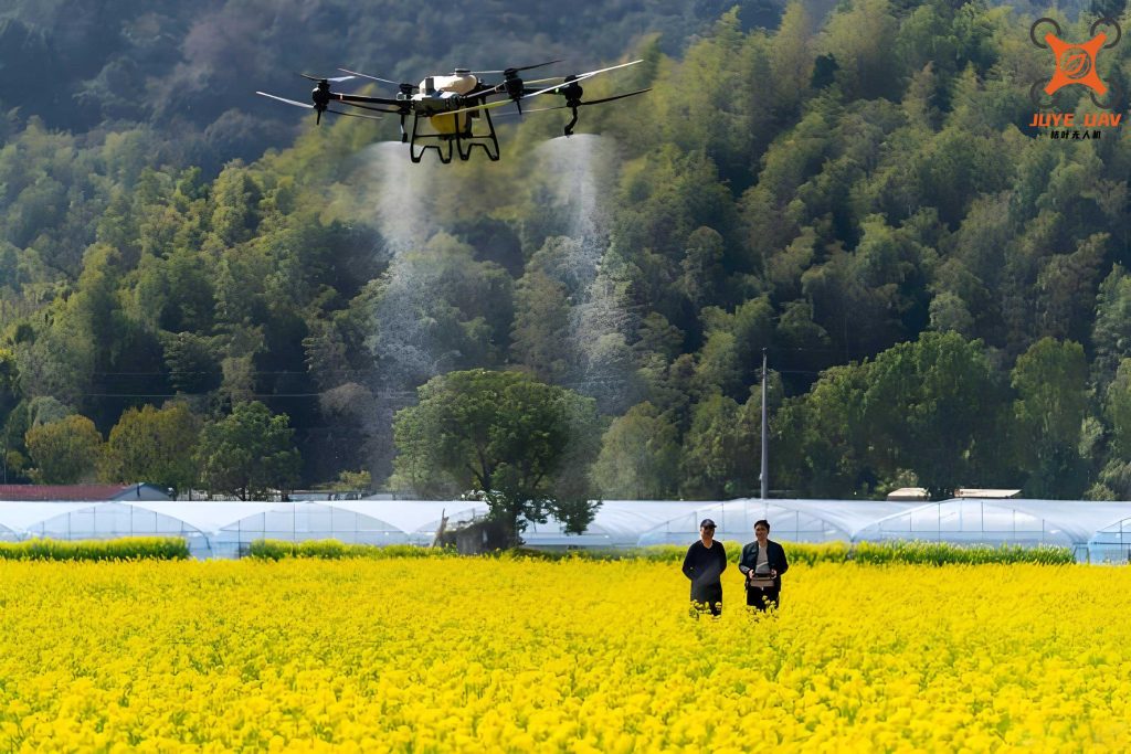
The integration of advanced modeling techniques with CFD simulations is essential for enhancing the performance of agricultural UAVs. In this work, I focus on the rotor, as its aerodynamic characteristics dictate the distribution of spray droplets and overall mission effectiveness. Reverse engineering offers a precise way to obtain digital models of physical components without relying on original design files, making it ideal for studying commercial agricultural UAV rotors. By combining this with experimental thrust measurements and CFD analysis, I aim to validate the reconstructed model’s fidelity. This approach not only supports rotor optimization but also contributes to broader research on agricultural UAV aerodynamics and spray systems.
The methodology is divided into three main phases: reverse modeling of the rotor, experimental thrust testing, and CFD numerical simulation. Each phase is meticulously designed to ensure data accuracy and reproducibility. For reverse modeling, I use a non-contact 3D scanner to capture point cloud data, process it in specialized software to generate surfaces, and finally create a solid model. The experimental setup involves a thrust test rig to measure rotor thrust across various rotational speeds. Finally, CFD simulations are conducted on the reverse-engineered model, with results compared against experimental data to assess errors. This comprehensive framework demonstrates how reverse engineering can be leveraged for agricultural UAV component analysis.
Reverse engineering begins with data acquisition. I employ an EinScan-SP 3D scanner, an optical non-contact device, to scan the DJI T20 rotor. The scanner uses white LED light and has a camera resolution of 1.3 megapixels, with a scanning depth ranging from 290 mm to 480 mm. To ensure optimal light reflection, the rotor is coated with a white contrast enhancer (FA-5 disparity enhancer) and positioned for top-down scanning. The rotor model is 3390 (33-inch diameter, 9-inch pitch), requiring multiple scans with overlapping feature points for accurate stitching. In total, 15 scans are performed, covering all details of the rotor surface. The scanner’s accuracy is 0.05 mm, with point spacing between 0.17 mm and 0.20 mm, and automatic stitching capabilities. The resulting point cloud contains approximately 3 million points, as shown in the data acquisition phase.
Point cloud processing is conducted in Geomagic Wrap software. Initial steps include removing non-connected items and outliers to eliminate noise from scanning artifacts. Subsequently, point cloud decimation is applied to reduce data volume while preserving points in high-curvature regions and boundaries. Through iterative sampling, the point cloud is精简 to around 300,000 points. This processed point cloud is then encapsulated to form a polygonal mesh. A new coordinate system is established: the XZ plane is defined as the mid-plane between the upper and lower surfaces of the rotor hub, the X-axis aligns parallel to the rotor tip plane, and the Y-axis is perpendicular to the XZ plane. This coordinate system is aligned globally to facilitate further modeling.
The polygonal mesh often contains defects such as holes, spikes, or intersecting faces, which are repaired using filling, smoothing, and mesh doctor tools. Once a clean mesh is obtained, precise surface reconstruction is performed. Instead of automatic surfacing, a stepwise approach is adopted due to the high curvature at the leading and trailing edges. This involves detecting contour lines, adjusting boundaries, partitioning the surface into regions, constructing surface patches, and fitting a final surface model. The resulting surface model is exported as a geometric file for further processing.
To evaluate the accuracy of the reverse-engineered model, a deviation analysis is conducted. The deviation cloud map indicates that most deviations range from -0.0494 mm to 0.0494 mm. The maximum deviation is 0.4201 mm, primarily at the leading and trailing edges, with a standard deviation of 0.0233 mm and an RMS estimate of 0.0235 mm. This level of precision is acceptable for engineering simulations involving agricultural UAV rotors. The surface model is then imported into SolidWorks, where actual assembly dimensions are measured, and a mirror operation is performed to create a complete three-dimensional solid model of the rotor. This model serves as the basis for subsequent CFD simulations.
The experimental phase involves thrust testing to obtain empirical data for validation. A test rig is constructed using components from the DJI T20 agricultural UAV: a motor (weight 666 g), a pair of rotors (weight 180 g), a Hobbywing Skywalker electronic speed controller (maximum continuous current 60 A, input voltage 22.2 V), an ACE format lithium polymer battery (rated voltage 22.2 V, capacity 16,000 mAh), a Mayatech MT10PRO thrust tester (maximum load 10 kg, error 1 g), a FUTABA 14SG remote controller, and a UNI-T UT330 tachometer (range 10 rpm to 9,999 rpm, error 0.1 rpm). The motor is mounted on a custom base attached to the thrust tester, ensuring the rotor plane is horizontal to avoid gravitational effects on measurements. The tachometer is fixed on a tripod and aligned with reflective tape on the motor for speed measurement.
Calibration is performed using standard weights (100 g, 500 g, 1000 g), confirming measurement errors within 1%. Tests are conducted by incrementally increasing throttle settings, allowing the rotor to stabilize at each speed, and recording thrust and rotational speed. The operational speed range is from 0 to 1,600 rpm, limited by the power supply’s maximum voltage. Three repeated tests yield consistent results, with thrust increasing monotonically with speed. The data is summarized in Table 1, which compares experimental thrust values with CFD simulation results at various speeds.
| Rotational Speed (rpm) | Experimental Thrust (g) | CFD Simulated Thrust (g) | Error (%) |
|---|---|---|---|
| 256 | 82 | 84 | 2.4 |
| 468 | 313 | 307 | -1.9 |
| 740 | 860 | 833 | -3.1 |
| 992 | 1,618 | 1,543 | -4.6 |
| 1,246 | 2,595 | 2,429 | -6.4 |
| 1,496 | 3,678 | 3,357 | -8.7 |
The CFD numerical simulation is conducted to predict rotor thrust and validate the reverse-engineered model. The flow field around the agricultural UAV rotor is considered three-dimensional, incompressible, and viscous, governed by the Navier-Stokes equations. In integral form, the conservation equations are expressed as:
$$ \frac{\partial}{\partial t} \int_{\Omega} \mathbf{Q} \, dV + \int_{\partial \Omega} \mathbf{F}(\mathbf{Q}) \cdot \mathbf{n} \, dS = \int_{\partial \Omega} \mathbf{G}(\mathbf{Q}) \cdot \mathbf{n} \, dS $$
where \( \Omega \) is the control volume, \( \partial \Omega \) is its boundary, \( \mathbf{Q} \) is the vector of conservative variables, \( dV \) is the volume element, \( dS \) is the surface area element, \( \mathbf{F} \) is the convective flux vector, \( \mathbf{n} \) is the outward normal vector, and \( \mathbf{G} \) is the viscous flux vector. For turbulence closure, the Realizable \( k-\epsilon \) model is employed, which enhances accuracy for rotating flows. The multiple reference frame (MRF) approach is used to handle rotor rotation, dividing the computational domain into a rotating zone enclosing the rotor and a stationary outer zone, simplifying the simulation to a steady-state problem.
Preprocessing involves domain creation and meshing. The computational domain, as illustrated in Figure 10, consists of a cylindrical rotating zone with diameter 1.05D and height 0.15D (where D is the rotor diameter), embedded within a larger stationary domain. The stationary domain extends 6D radially from the rotating zone, 6D upstream from the inlet, and 12D downstream to the outlet. Mesh generation is critical for resolving flow details; after grid independence tests at 1,500 rpm, optimal parameters are set: maximum surface mesh size of 5 mm, local minimum size of 1 mm, boundary layer first layer thickness of 0.25 mm, total thickness of 2 mm, and interface mesh size of 25 mm. The total mesh count is approximately 2 million elements.
Boundary conditions are defined as follows: inlet and outlet are set as pressure boundaries with reference pressure at standard atmosphere, walls are fixed no-slip boundaries, and the rotor surface is a moving wall with zero relative velocity in the rotating frame. The solver uses the SIMPLE algorithm for pressure-velocity coupling, with second-order discretization schemes and a convergence criterion of 0.00001. Simulations are run at rotational speeds matching the experimental range, and thrust is extracted from the converged solutions.
The CFD results show good agreement with experimental data, as depicted in Figure 11 and Table 1. Thrust increases with speed in both cases, but simulation values tend to be slightly lower at higher speeds, with errors growing up to 8.7% at 1,496 rpm. This trend is consistent with literature on propeller simulations, often attributed to simplifications in turbulence modeling or mesh limitations. The overall fit validates the reverse-engineered model’s accuracy for agricultural UAV rotor studies.
To further analyze the aerodynamic behavior, I derive key performance metrics. The thrust coefficient \( C_T \) and power coefficient \( C_P \) are defined as:
$$ C_T = \frac{T}{\rho n^2 D^4}, \quad C_P = \frac{P}{\rho n^3 D^5} $$
where \( T \) is thrust, \( \rho \) is air density, \( n \) is rotational speed in revolutions per second, \( D \) is rotor diameter, and \( P \) is power. Using experimental data, these coefficients can be calculated to compare with theoretical models. For instance, at 1,246 rpm, \( n \approx 20.77 \, \text{rps} \), \( D = 0.8382 \, \text{m} \) (33 inches), \( \rho = 1.225 \, \text{kg/m}^3 \), and \( T = 2.595 \, \text{kg} \cdot 9.81 \, \text{m/s}^2 = 25.44 \, \text{N} \). Thus,
$$ C_T = \frac{25.44}{1.225 \times (20.77)^2 \times (0.8382)^4} \approx 0.012 $$
Similar calculations for other speeds reveal how \( C_T \) varies, providing insight into rotor efficiency. This is crucial for optimizing agricultural UAV rotors for specific operational conditions.
The reverse modeling process highlights several advantages for agricultural UAV applications. By capturing exact geometry, it enables detailed studies of blade twist, airfoil shape, and tip effects, which influence spray dispersion. Moreover, the method is non-destructive, allowing analysis of existing rotors without modification. However, challenges include handling reflective surfaces and complex curvatures, necessitating careful scanning and processing. Future work could integrate this with spray simulation to model droplet trajectories under rotor downwash, further enhancing agricultural UAV design.
In terms of CFD validation, the errors observed warrant discussion. Potential sources include: (1) simplifications in the turbulence model, which may not fully capture vortical structures at high speeds; (2) mesh resolution limitations near the blade edges; (3) assumptions in the MRF approach, which neglects unsteady effects; and (4) experimental uncertainties, such as motor vibrations or environmental factors. To mitigate these, finer meshing, transient simulations, or advanced turbulence models like DES could be explored. Nonetheless, for practical agricultural UAV engineering, the current error margin is acceptable, supporting the use of reverse-engineered models in iterative design processes.
The impact of rotor design on agricultural UAV performance cannot be overstated. Efficient rotors reduce energy consumption, extend flight time, and improve spray uniformity. By combining reverse engineering with CFD, designers can rapidly prototype and test modifications, such as changing blade pitch or adding winglets. This accelerates innovation in agricultural UAV technology, contributing to sustainable farming practices. For example, optimized rotors might enhance droplet penetration into crop canopies, reducing pesticide drift and increasing efficacy.
Beyond thrust, the reverse-engineered model facilitates analysis of other aerodynamic quantities. Pressure distributions on the blade surface can be extracted from CFD to identify regions of high load or separation. Velocity contours in the wake reveal the downwash structure, which is critical for understanding how spray is transported. These insights are valuable for developing next-generation agricultural UAVs with tailored rotor systems for specific crops or terrains.
To contextualize this work, I compare it with existing studies on agricultural UAV rotors. Previous research often relies on simplified analytical models or proprietary CAD data, limiting accessibility. The reverse engineering approach democratizes analysis, enabling researchers and practitioners to study commercial rotors without internal design files. Additionally, the integration of experimental validation strengthens confidence in simulation results, a step sometimes overlooked in prior work.
The methodology presented here is scalable to other agricultural UAV components, such as fuselages or spray nozzles. By applying similar scanning and simulation techniques, holistic optimization of entire UAV systems becomes feasible. This aligns with trends in digital agriculture, where data-driven tools enhance precision farming. As agricultural UAVs evolve, such methodologies will play a pivotal role in achieving higher efficiency and environmental friendliness.
In conclusion, this study demonstrates a comprehensive workflow for reverse modeling and numerical simulation of an agricultural UAV rotor. The process involves 3D scanning, point cloud processing, surface reconstruction, experimental thrust testing, and CFD analysis. Results show that the reverse-engineered model achieves sufficient accuracy, with simulation errors within 8.7% across the operational speed range. This validates the feasibility of using reverse engineering for agricultural UAV rotor studies, providing a foundation for future research on aerodynamics and spray dynamics. The approach not only aids in rotor optimization but also underscores the importance of interdisciplinary techniques in advancing agricultural UAV technology for sustainable crop protection.
Future directions include extending the simulation to include spray droplets, coupling with flight dynamics models, and exploring additive manufacturing of optimized rotor designs. By continuing to refine these methods, the agricultural UAV community can develop more effective solutions to global farming challenges, ensuring food security and environmental stewardship.