
In recent years, the quadrotor drone has emerged as a highly versatile unmanned aerial vehicle (UAV) due to its compact design, agility, and strong integration capabilities. Compared to conventional UAVs, the quadrotor drone offers significant advantages in applications such as traffic monitoring, fire detection, environmental surveillance, and search-and-rescue operations. The quadrotor drone operates with four rotors arranged in a cross configuration, allowing for precise control of flight attitude and direction through differential rotor speeds. However, the quadrotor drone presents challenges including nonlinear dynamics, inherent instability, strong coupling between axes, and significant error accumulation in inertial navigation systems. To address these issues, this research focuses on developing a navigation method for a quadrotor drone based on a strap-down inertial navigation system (SINS). By leveraging micro-electromechanical systems (MEMS) sensors, we integrate real-time attitude data from an MPU6050 combination sensor (3-axis gyroscope and 3-axis accelerometer) and an HMC5883L 3-axis magnetoresistive sensor, using the Digital Motion Processor (DMP) algorithm provided by InvenSenseTM for attitude resolution. A Proportional-Integral-Derivative (PID) control algorithm is employed for closed-loop adjustment of the quadrotor drone’s flight attitude. Experimental results demonstrate that the quadrotor drone achieves stable flight, validating the effectiveness of the proposed approach.
The system architecture of the quadrotor drone comprises several key components, as summarized in Table 1. The core processor is an STM32F103 microcontroller, which handles sensor data acquisition, attitude calculation, and control signal generation. The inertial measurement unit includes an MPU6050 for angular rate and linear acceleration sensing, and an HMC5883L for magnetic field measurement to determine heading. The propulsion system consists of brushless motors driven by electronic speed controllers (ESCs), while communication is facilitated via a wireless remote control platform and a ground-based上位机 (ground station) for monitoring. This integrated design ensures lightweight construction and high flexibility for the quadrotor drone.
| Component | Description |
|---|---|
| Microprocessor | STM32F103 for processing and control |
| Inertial Sensors | MPU6050 (gyroscope + accelerometer) and HMC5883L (magnetometer) |
| Motor Drivers | ESC modules for brushless motors |
| Communication | Wireless remote and ground station interface |
| Power System | Lithium-polymer battery and distribution board |
To model the quadrotor drone, we establish a dynamics framework based on Newton-Euler equations. The quadrotor drone utilizes four rotors, with two rotating clockwise and two counterclockwise to cancel out reactive torques, enabling stable hover. The forces and moments generated by the rotors dictate the motion. Let $F_i$ denote the lift force from rotor $i$ ($i=1,2,3,4$), $m$ the mass of the quadrotor drone, $g$ gravitational acceleration, $r$ the arm length from center to rotor, and $I_x$, $I_y$, $I_z$ the moments of inertia about the body-fixed $X$, $Y$, and $Z$ axes, respectively. The dynamics can be expressed as:
$$
\sum_{i=1}^{4} F_i = m g
$$
$$
\ddot{\alpha} = \frac{r (F_4 – F_2)}{I_y}
$$
$$
\ddot{\beta} = \frac{r (F_1 – F_3)}{I_x}
$$
$$
\ddot{\gamma} = \frac{k_2 F_2 + k_4 F_4 – k_1 F_1 – k_3 F_3}{I_z}
$$
$$
\ddot{x} = F_x / m
$$
$$
\ddot{y} = F_y / m
$$
$$
\ddot{z} = F_z / m
$$
Here, $\alpha$, $\beta$, and $\gamma$ represent the pitch, roll, and yaw angles of the quadrotor drone, respectively, while $x$, $y$, $z$ denote positions in the inertial frame. The coefficients $k_i$ relate rotor lift to torque. For attitude control, we define the input vector $\mathbf{u}$ as:
$$
\mathbf{u} = \begin{bmatrix}
u_1 \\
u_2 \\
u_3 \\
u_4
\end{bmatrix} = \begin{bmatrix}
\sum_{i=1}^{4} F_i \\
r (F_4 – F_2) \\
r (F_1 – F_3) \\
k (F_1 – F_2 + F_3 – F_4)
\end{bmatrix}
$$
The transformation between the body frame ($OX_bY_bZ_b$) and the geographic reference frame ($OX_mY_mZ_m$) is crucial for navigation. Assuming rotations in the order yaw ($\gamma$), pitch ($\beta$), and roll ($\alpha$), the rotation matrix $\mathbf{R}$ is:
$$
\mathbf{R} = \begin{bmatrix}
\cos\beta \cos\gamma & \sin\alpha \sin\beta \cos\gamma – \sin\gamma \cos\alpha & -\sin\alpha \cos\gamma – \sin\gamma \sin\beta \cos\alpha \\
-\cos\beta \sin\gamma & \cos\alpha \cos\gamma – \sin\gamma \sin\alpha \sin\beta & \sin\gamma \sin\beta \cos\alpha + \cos\gamma \sin\alpha \\
\sin\beta & -\sin\alpha \cos\beta & \cos\alpha \cos\beta
\end{bmatrix}
$$
This allows us to express the dynamics in state-space form. Let $\mathbf{X} = (\dot{x}, \dot{y}, \dot{z}, \dot{\alpha}, \dot{\beta}, \dot{\gamma}, \alpha, \beta, \gamma)^T$ and $\mathbf{Y} = (\dot{x}, \dot{y}, \dot{z}, \dot{\alpha}, \dot{\beta}, \dot{\gamma}, \alpha, \beta, \gamma)^T$. The state and output equations are:
$$
\dot{\mathbf{X}} = \mathbf{A} \mathbf{X} + \mathbf{B} \mathbf{u}
$$
$$
\mathbf{Y} = \mathbf{C} \mathbf{X} + \mathbf{D} \mathbf{u}
$$
With small-angle approximations and neglecting couplings, the transfer functions for each channel of the quadrotor drone can be derived. Using parameters from our custom-built quadrotor drone (Table 2), we obtain the following transfer functions (Table 3).
| Parameter | Value |
|---|---|
| Arm length, $r$ (m) | 0.245 |
| Mass, $m$ (kg) | 1.05 |
| Moment of inertia, $I_x$ (kg·m²) | 6.2 × 10⁻³ |
| Moment of inertia, $I_y$ (kg·m²) | 6.2 × 10⁻³ |
| Moment of inertia, $I_z$ (kg·m²) | 3.0 × 10⁻² |
| Control Channel | Transfer Function |
|---|---|
| Altitude (Z-axis) | $G_1(s) = \dfrac{0.9524}{s^2}$ |
| Pitch | $G_2(s) = \dfrac{161.29}{s^2}$ |
| Roll | $G_3(s) = \dfrac{161.29}{s^2}$ |
| Yaw | $G_4(s) = \dfrac{33.33}{s^2}$ |
Attitude measurement for the quadrotor drone relies on MEMS sensors. The gyroscope provides angular rate data with high dynamic response but suffers from drift over time. The accelerometer measures linear acceleration, offering stable low-frequency data but is sensitive to vibrations. The magnetometer senses Earth’s magnetic field for heading, yet is prone to external magnetic disturbances. To fuse these data, we explore several attitude resolution algorithms. The complementary filter combines high-frequency components from the gyroscope with low-frequency components from the accelerometer and magnetometer. Let $\mathbf{R}$ be the true attitude matrix, $\mathbf{R}_{\text{gyro}}$ the gyroscope output with high-frequency noise $\mathbf{N}_H$, and $\mathbf{R}_{\text{mix}}$ the combined accelerometer-magnetometer output with low-frequency noise $\mathbf{N}_L$. The estimated attitude $\hat{\mathbf{R}}$ is:
$$
\hat{\mathbf{R}}(s) = F_L(s) \mathbf{R}_{\text{mix}}(s) + F_H(s) \mathbf{R}_{\text{gyro}}(s) \approx \mathbf{R}(s)
$$
where $F_L(s) = \dfrac{K}{s + K}$ and $F_H(s) = \dfrac{s}{s + K}$ with $F_L(s) + F_H(s) = 1$. For the quadrotor drone, separate filter coefficients $K_1$ and $K_2$ are used for accelerometer and magnetometer data, respectively.
Kalman filtering offers another approach for the quadrotor drone, optimizing state estimation in the presence of noise. The system model includes state vector $\mathbf{X} = [\theta, \omega_e]^T$, where $\theta$ is the attitude angle and $\omega_e$ is gyroscope bias. The state and observation equations are:
$$
\dot{\mathbf{X}} = \begin{bmatrix} 0 & -1 \\ 0 & 0 \end{bmatrix} \mathbf{X} + \begin{bmatrix} 1 \\ 0 \end{bmatrix} u + \mathbf{W}
$$
$$
\mathbf{Z} = \begin{bmatrix} 1 & 0 \end{bmatrix} \mathbf{X} + \mathbf{V}
$$
Here, $u = \omega_{\text{gyro}}$ is the gyroscope output, $\mathbf{W}$ and $\mathbf{V}$ are process and observation noise with covariances $\mathbf{Q}$ and $\mathbf{R}$. Discretizing with sample time $T_s$:
$$
\mathbf{X}(k) = \begin{bmatrix} 1 & T_s \\ 0 & 1 \end{bmatrix} \mathbf{X}(k-1) + \begin{bmatrix} T_s \\ 0 \end{bmatrix} u(k-1) + \mathbf{W}(k)
$$
$$
\mathbf{Z}(k) = \begin{bmatrix} 1 & 0 \end{bmatrix} \mathbf{X}(k) + \mathbf{V}(k)
$$
The Kalman filter proceeds with prediction and update steps. The prediction equations are:
$$
\hat{\mathbf{X}}(k|k-1) = \mathbf{A} \hat{\mathbf{X}}(k-1|k-1) + \mathbf{B} u(k)
$$
$$
\mathbf{P}(k|k-1) = \mathbf{A} \mathbf{P}(k-1|k-1) \mathbf{A}^T + \mathbf{Q}
$$
where $\mathbf{P}$ is the error covariance. The update equations include the Kalman gain $\mathbf{K}_g(k)$:
$$
\mathbf{K}_g(k) = \frac{\mathbf{P}(k|k-1) \mathbf{H}^T}{\mathbf{H} \mathbf{P}(k|k-1) \mathbf{H}^T + \mathbf{R}}
$$
$$
\hat{\mathbf{X}}(k|k) = \hat{\mathbf{X}}(k|k-1) + \mathbf{K}_g(k) (\mathbf{Z}(k) – \mathbf{H} \hat{\mathbf{X}}(k|k-1))
$$
$$
\mathbf{P}(k|k) = (\mathbf{I} – \mathbf{K}_g(k) \mathbf{H}) \mathbf{P}(k|k-1)
$$
For the quadrotor drone, this reduces attitude estimation errors but requires tuning of $\mathbf{Q}$ and $\mathbf{R}$.
Alternatively, the DMP algorithm embedded in the MPU6050 provides a hardware-accelerated solution for the quadrotor drone. The DMP fuses sensor data internally and outputs attitude in quaternion, Euler angle, or rotation matrix formats, minimizing computational load on the microcontroller. This method is efficient for real-time control of the quadrotor drone, as it avoids complex software filtering and reduces power consumption.
In our implementation for the quadrotor drone, we utilize the DMP to compute attitude angles, which are then fed into a PID controller. The PID control law for each axis (e.g., pitch) is:
$$
u(t) = K_p e(t) + K_i \int_0^t e(\tau) d\tau + K_d \frac{de(t)}{dt}
$$
where $e(t)$ is the error between desired and measured attitude, and $K_p$, $K_i$, $K_d$ are tuned gains. This closed-loop system ensures stable flight of the quadrotor drone.
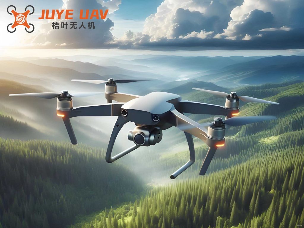
The custom-built quadrotor drone platform was tested to validate the navigation approach. Attitude data from the DMP were transmitted wirelessly to a ground station for monitoring. As shown in the response curves, the quadrotor drone maintains pitch, roll, and yaw angles within ±5° during flight, indicating effective stabilization. The PID parameters were empirically adjusted to achieve this performance, demonstrating that the strap-down inertial system with DMP resolution is viable for quadrotor drone applications.
In conclusion, this research presents a comprehensive method for navigating a quadrotor drone using a strap-down inertial navigation system. By modeling the dynamics, fusing MEMS sensor data via the DMP algorithm, and applying PID control, we achieve stable flight with minimal attitude errors. The quadrotor drone proves to be a robust platform for various low-altitude tasks, and future work could enhance autonomy through advanced control strategies or machine learning. The integration of lightweight sensors and efficient algorithms makes this approach scalable for diverse quadrotor drone deployments.