In the context of global carbon reduction goals, the aviation sector faces pressing demands to lower emissions, with civil aviation accounting for approximately 2.5% to 4.0% of global carbon output. The NASA N+3 initiative targets a 60% reduction in aircraft fuel consumption by 2025, driving innovation in green aviation technologies. Among unmanned aerial vehicles (UAVs), vertical take-off and landing (VTOL) fixed-wing UAVs combine the advantages of multi-rotor and fixed-wing designs, offering versatility in applications such as surveillance, delivery, and environmental monitoring. However, electric propulsion systems, particularly battery-based ones, often suffer from limited endurance, constraining their operational scope. Proton exchange membrane fuel cells (PEMFCs) emerge as a promising solution due to their high energy density, zero emissions, and high conversion efficiency. Yet, PEMFCs exhibit soft output characteristics and low power density, struggling to meet instantaneous power demands during flight disturbances or mode transitions in VTOL UAVs. To address this, hybrid power systems integrating PEMFCs with high-power-density auxiliary sources like lithium-ion batteries are essential. This article presents a comprehensive parameter matching methodology for a hybrid power system in a VTOL fixed-wing UAV, employing a PEMFC and lithium-ion battery configuration. We detail the system topology, component selection, energy management strategy, and validation through simulation and hardware-in-the-loop experiments, aiming to enhance endurance and performance while ensuring zero-emission flight.
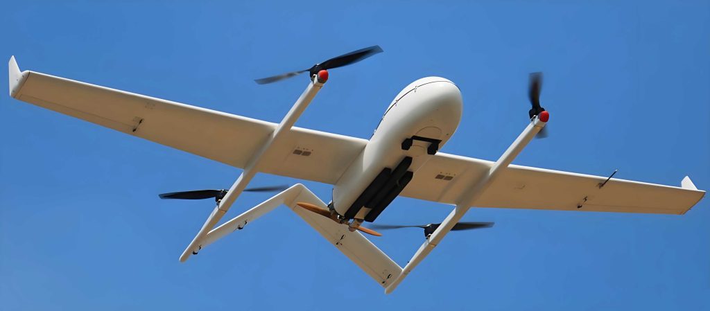
The VTOL fixed-wing UAV in this study features a design with four rotor propellers for vertical lift and one pusher propeller for forward thrust in fixed-wing mode. Key technical parameters are summarized in Table 1. This configuration enables efficient hover and cruise capabilities, but it demands a power system that can handle diverse operational profiles, including vertical take-off, climb, hover, transition, cruise, and landing. The hybrid power system adopts a parallel topology, as illustrated in the system configuration diagram. The PEMFC connects to the load bus via a unidirectional DC/DC converter, primarily supplying energy during cruise and recharging the battery when needed. The lithium-ion battery links directly to the bus, providing peak power during high-demand phases like take-off and transient maneuvers. This setup leverages the high energy density of the PEMFC and the high power density of the battery, ensuring reliable performance across all flight conditions for the VTOL UAV.
| Parameter | Value |
|---|---|
| Maximum Take-off Mass (kg) | 85 |
| Cruise Speed (m/s) | 33.34 |
| Maximum Flight Speed (m/s) | 41.67 |
| Number of Brushless DC Motors | 5 |
| Wing Loading (kg/m²) | 35.66 |
| Lift-to-Drag Ratio | 12 |
| Vertical Take-off Acceleration (m/s²) | 0.125 |
Parameter matching for the hybrid power system is critical to meet the VTOL UAV’s flight profile demands. We begin with the brushless DC motor and propeller selection. For vertical take-off and hover, the VTOL UAV relies on four rotor propellers. The thrust required per propeller during hover is derived from the equilibrium of lift and weight:
$$ T = \frac{m_{\text{copter}}}{n_p} g $$
where \( T \) is the thrust per propeller, \( m_{\text{copter}} = 85 \, \text{kg} \) is the maximum take-off mass, \( n_p = 4 \) is the number of rotor propellers, and \( g = 9.81 \, \text{m/s}^2 \). Including a safety factor \( a_{\text{safe}} = 1.6 \), the maximum thrust per propeller during hover is:
$$ T_{\text{hover}} = a_{\text{safe}} T $$
Calculations yield \( T = 208.46 \, \text{N} \) and \( T_{\text{hover}} = 333.54 \, \text{N} \). During vertical ascent with acceleration \( a = 0.125 \, \text{m/s}^2 \), the thrust per propeller becomes:
$$ T_1 = \frac{m_{\text{copter}}}{n_p} (g + a) $$
with \( T_1 = 210.99 \, \text{N} \) and maximum thrust \( T_{\text{max}} = a_{\text{safe}} T_1 = 337.79 \, \text{N} \). This corresponds to a per-motor thrust of approximately 34.4 kg. Based on this, we select the T-motor U15II KV100 motor, paired with T-motor 40×13.1 propellers. The motor specifications are listed in Table 2. The total propulsion efficiency \( \eta_{t}^{mp} \) of the motor-propeller system is expressed as:
$$ \eta_{t}^{mp} = \frac{1}{\left( \frac{\pi C_M D_P}{30 K_E C_T} \right)^2 R_m T + \frac{2 \pi C_M}{D_P \rho C_T^3} T } $$
where \( C_T = 0.0996 \) and \( C_M = 0.0054 \) are the thrust and torque coefficients, \( D_P \) is the propeller diameter, \( R_m \) is the motor internal resistance, and \( K_E \) is a motor parameter given by:
$$ K_E = \frac{U_{m0} – I_{m0} R_m}{K_V U_{m0}} $$
Using values from Table 2, we compute \( \eta_{t}^{mp} = 0.0449 \, \text{N/W} \), meaning 44.9 N of thrust per kW of input. Thus, the power required per propeller during maximum ascent is:
$$ P_{\text{Load max}} = \frac{T_{\text{max}}}{\eta_{t}^{mp}} $$
resulting in \( P_{\text{Load max}} = 7.52 \, \text{kW} \) per propeller. For four rotors, the total power demand during vertical ascent is 30.09 kW. This high power requirement underscores the need for a hybrid system in the VTOL UAV to manage peak loads effectively.
| Parameter | Value |
|---|---|
| Voltage (V) | 50 |
| No-load Current (A) | 4.5 |
| KV (rpm/V) | 100 |
| Internal Resistance (mΩ) | 20 |
| Mass (g) | 1740 |
| Maximum Current (A) | 171 |
Next, we size the PEMFC for the VTOL UAV. During cruise, the power required is determined by the aerodynamic performance:
$$ P_{VC} = \frac{m_{\text{copter}} g}{(L/D)_{V_C}} V_C $$
where \( V_C = 33.34 \, \text{m/s} \) is the cruise speed and \( (L/D)_{V_C} = 12 \) is the lift-to-drag ratio. With the safety factor, \( P_{VC} = 3.71 \, \text{kW} \). For maximum level flight at \( V_{C \text{max}} = 41.67 \, \text{m/s} \), the power is:
$$ P_{VC \text{max}} = \frac{m_{\text{copter}} g}{(L/D)_{V_{C \text{max}}}} V_{C \text{max}} $$
yielding \( P_{VC \text{max}} = 4.64 \, \text{kW} \). The PEMFC output power should cover these needs, ideally operating near its peak efficiency. We select a PEMFC with a rated power of 4.8 kW and peak power of 10 kW, as detailed in Table 3. This ensures the VTOL UAV can sustain cruise while providing margin for auxiliary functions.
| Parameter | Value |
|---|---|
| Rated Power (kW) | 4.8 |
| Peak Power (kW) | 10 |
| Maximum Current (A) | 300 |
| Operating Temperature (°C) | -40 to 60 |
The lithium-ion battery complements the PEMFC by supplying transient and high-power demands. Its maximum power must satisfy:
$$ P_{\text{Li max}} \geq P_{\text{Load max}} – P_{\text{fc}} $$
where \( P_{\text{Load max}} = 30.09 \, \text{kW} \) and \( P_{\text{fc}} = 4.8 \, \text{kW} \), giving \( P_{\text{Li max}} \geq 25.28 \, \text{kW} \). Considering the VTOL UAV’s vertical take-off phase, where the PEMFC response is slow, we choose a battery with a peak power of 30 kW. The capacity is estimated based on operational durations: 60 s for take-off and 100 s for transition. The required capacity \( Q \) is calculated as:
$$ Q_1 = \frac{m_1 I_{\text{motor}} t_1}{3600 \times 1000} \quad \text{and} \quad Q_2 = \frac{m_2 I_{\text{motor}} t_2}{3600 \times 1000} $$
with \( m_1 = 4 \) motors during take-off, \( I_{\text{motor}} = 171 \, \text{A} \), \( t_1 = 60 \, \text{s} \), \( m_2 = 5 \) motors during transition, \( t_2 = 100 \, \text{s} \). This gives \( Q_1 = 11.4 \, \text{A·h} \) and \( Q_2 = 23.75 \, \text{A·h} \), so \( Q > 35.15 \, \text{A·h} \). We select four ACE 22000 mAh 6S 25C lithium-ion batteries arranged in a 2S2P configuration, providing a total voltage of 50 V and capacity of 44 A·h, as shown in Table 4. This setup meets the VTOL UAV’s energy and power requirements robustly.
| Parameter | Value |
|---|---|
| Voltage (V) | 50 |
| Capacity (A·h) | 44 |
| Configuration | 2S2P |
| Number of Batteries | 4 |
| Mass per Battery (kg) | 2.325 |
The unidirectional DC/DC converter interfaces the PEMFC to the bus, stepping up its voltage. Its power rating should exceed the PEMFC’s maximum output, so we choose a converter with 16 kW capacity and 98% efficiency, as per Table 5. This ensures efficient power transfer in the VTOL UAV hybrid system.
| Parameter | Value |
|---|---|
| Voltage (V) | >50 |
| Current (A) | >300 |
| Power (kW) | 16 |
| Efficiency (%) | 98 |
Energy management is crucial for optimizing the hybrid power system in the VTOL UAV. We design a finite state machine (FSM) strategy with the following constraints: (1) the battery state of charge (SOC) is maintained between 60% and 85% during flight; (2) during take-off, the battery provides peak power, while the PEMFC operates near rated power during cruise; and (3) transient power demands are handled by the battery. The FSM strategy, depicted in a state diagram, allocates power based on load requirements and SOC levels. For instance, if the SOC is high, both sources share the load; if SOC drops below 60%, the PEMFC charges the battery while powering the load. This approach ensures efficient utilization of both energy sources, enhancing the endurance and reliability of the VTOL UAV.
To validate the parameter matching, we develop a simulation model in MATLAB/Simulink, comprising PEMFC, lithium-ion battery, DC/DC converter, energy management controller, and load modules. The load power profile, as shown in Figure 1, encompasses vertical take-off, transition, cruise, and transient phases, reflecting real-world operational demands for the VTOL UAV. The FSM controller modulates the DC/DC converter duty cycle to regulate PEMFC output, while the battery responds dynamically to load changes. Simulation results with an initial battery SOC of 80% demonstrate effective power sharing. At startup, the battery supplies immediate power due to the PEMFC’s slow response; subsequently, both sources contribute. When SOC falls below 60%, the PEMFC prioritizes charging while meeting load demands. The power distribution and SOC trends, illustrated in Figure 2, confirm that the hybrid system meets the VTOL UAV’s flight profile requirements, with the PEMFC operating efficiently near its rated point during cruise.
We further conduct hardware-in-the-loop (HIL) experiments using an M2C controller development platform with an MPC5634M chip and SNC controller. The HIL setup, shown in Figure 3, implements the FSM strategy in an embedded environment, compiling C code via CodeWarrior. Results for battery SOC and PEMFC power output align closely with simulations, as compared in Figure 4 and Figure 5, validating the parameter matching approach. The battery current and voltage profiles, depicted in Figure 6 and Figure 7, show that the system tracks load power effectively, with the battery handling peaks up to 300 A and 50 V. This consistency between simulation and HIL experiments underscores the robustness of the hybrid power system design for the VTOL UAV.
In summary, this article presents a systematic parameter matching methodology for a PEMFC-lithium-ion hybrid power system in a VTOL fixed-wing UAV. The process involves selecting components based on detailed calculations of thrust, power, and energy requirements across flight phases. The FSM energy management strategy ensures optimal power allocation, maintaining battery health and PEMFC efficiency. Simulation and HIL experiments confirm that the system meets the VTOL UAV’s operational demands, enabling zero-emission flight with enhanced endurance. Future work could explore advanced control algorithms or component optimizations to further improve performance. This study provides a foundational framework for hybrid power system design in VTOL UAVs, contributing to green aviation advancements.