
The choreography of a modern formation drone light show represents a pinnacle of coordination, where hundreds of unmanned aerial vehicles (UAVs) must execute precise, synchronized flight paths to create complex aerial imagery. The core challenge lies in optimizing these formation trajectories to ensure not only stunning visual fidelity but also operational safety and efficiency. Sub-optimal paths lead to longer flight times, increased energy consumption, and heightened risk of in-air collisions, ultimately shortening the operational lifespan of the drone fleet. This work introduces a novel trajectory optimization method for quadrotor UAV formations, specifically tailored for the demands of a formation drone light show, based on an Adaptive Coyote Optimization Algorithm (ACOA). The method constructs a detailed kinematic model of the formation, establishes pertinent flight constraints, plans collision-free paths using a repulsive potential field, and employs the adaptive metaheuristic to minimize the error between desired and actual formation geometry, thereby generating highly efficient and safe flight trajectories.
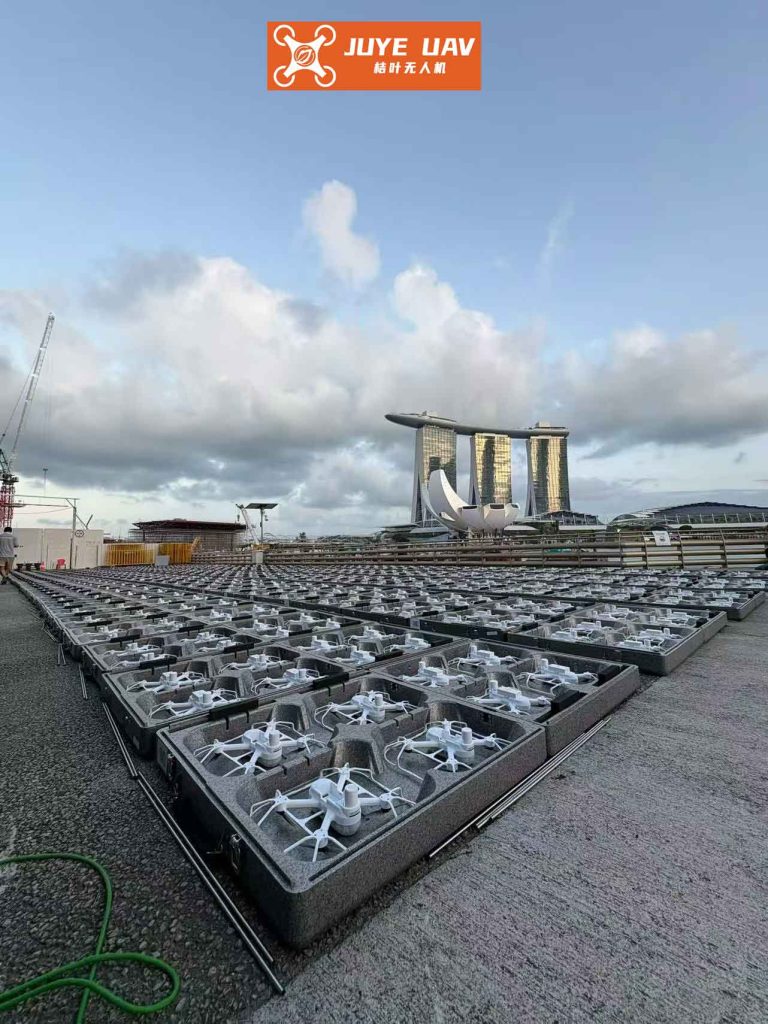
The execution of a large-scale formation drone light show is a complex multi-agent control problem. Each drone in the formation must adhere to a time-parameterized position in 3D space, defining the overall shape. Deviations from these paths result in visual artifacts and safety hazards. Traditional methods often struggle with the non-linearity of drone dynamics, real-time computational constraints, and the need to avoid both static obstacles and other members of the formation. This paper addresses these issues by integrating a bio-inspired optimization strategy with established robotic principles to produce smoother, faster, and more reliable trajectories essential for a flawless formation drone light show.
1. Kinematic and Dynamic Modeling of a Quadrotor Formation
To optimize the trajectory of a formation drone light show, a precise mathematical representation of each agent’s motion is fundamental. We begin by defining two coordinate systems for each drone in the formation.
- Body Frame (B): The origin is at the drone’s center of mass. The \(x_B\)-axis points forward (through two rotors), the \(y_B\)-axis points to the right, and the \(z_B\)-axis points downward, completing a right-handed system.
- Inertial Frame (I): A fixed world coordinate system, typically with its origin at the launch point, with \(x_I\), \(y_I\), and \(z_I\) axes aligned north, east, and down, respectively.
The attitude of the drone is described by the Euler angles—roll (\(\phi\)), pitch (\(\theta\)), and yaw (\(\psi\))—defining the rotation from the inertial frame to the body frame. The dynamics are derived from Newton-Euler equations, considering forces (thrust, gravity, drag) and moments. The angular acceleration in the body frame is given by:
$$
\begin{aligned}
\dot{p} &= \frac{l U_2 + q r (I_{yy} – I_{zz})}{I_{xx}} \\
\dot{q} &= \frac{l U_3 + p r (I_{zz} – I_{xx})}{I_{yy}} \\
\dot{r} &= \frac{l U_4 + p q (I_{xx} – I_{yy})}{I_{zz}}
\end{aligned}
$$
where \(p, q, r\) are the angular rates (roll, pitch, yaw) in the body frame, \(I_{xx}, I_{yy}, I_{zz}\) are the moments of inertia, \(l\) is the arm length from the center of mass to a rotor, and \(U_2, U_3, U_4\) are control inputs related to the moments.
The translational acceleration in the inertial frame, derived from the thrust vector rotation and gravity, is:
$$
\begin{aligned}
\ddot{x} &= \frac{U_1}{m} (\cos\phi \sin\theta \cos\psi + \sin\phi \sin\psi) \\
\ddot{y} &= \frac{U_1}{m} (\cos\phi \sin\theta \sin\psi – \sin\phi \cos\psi) \\
\ddot{z} &= \frac{U_1}{m} (\cos\phi \cos\theta) – g
\end{aligned}
$$
Here, \([\ddot{x}, \ddot{y}, \ddot{z}]^T\) is the acceleration in the inertial frame, \(m\) is the drone mass, \(g\) is gravitational acceleration, and \(U_1\) is the total thrust control input. This model forms the basis for predicting and controlling the motion of every unit within the formation drone light show.
For a formation of \(N\) drones, we define a state vector \(\mathbf{X}_i\) for the \(i\)-th drone and a combined formation state \(\mathbf{X} = [\mathbf{X}_1^T, \mathbf{X}_2^T, …, \mathbf{X}_N^T]^T\). A key variable for formation control is the relative distance between drones \(i\) and \(k\):
$$
D_{ik}(t) = || \mathbf{P}_i(t) – \mathbf{P}_k(t) ||
$$
where \(\mathbf{P}_i(t) = [x_i(t), y_i(t), z_i(t)]^T\) is the position of drone \(i\). Maintaining the desired distance \(D_{ik}^{des}\) is crucial for the integrity of the formation drone light show pattern.
| Parameter | Symbol | Value | Unit |
|---|---|---|---|
| Mass | \(m\) | 0.087 | kg |
| Arm Length | \(l\) | 0.12 | m |
| Gravity | \(g\) | 9.81 | m/s² |
| Inertia (x-axis) | \(I_{xx}\) | 1.3186 × 10⁻⁴ | kg·m² |
| Inertia (y-axis) | \(I_{yy}\) | 1.19696 × 10⁻⁴ | kg·m² |
| Inertia (z-axis) | \(I_{zz}\) | 1.7998 × 10⁻⁴ | kg·m² |
| Thrust Coefficient | \(k_f\) | 3.13 × 10⁻⁵ | N/rpm² |
| Drag Coefficient | \(k_m\) | 7.5 × 10⁻⁷ | Nm/rpm² |
2. Formulation of Formation Trajectory Optimization
2.1 Constraint Definition
The trajectory for a formation drone light show must satisfy multiple physical and operational constraints to be feasible and safe.
- Kinematic/Dynamic Constraints: The trajectory must be consistent with the model in Section 1. Control inputs \(U_1, U_2, U_3, U_4\) are bounded:
$$U_{1}^{min} \leq U_1 \leq U_{1}^{max}, \quad |U_{2,3,4}| \leq U_{max}^{moment}$$ - Collision Avoidance: A minimum safe distance \(d_{min}\) must be maintained between all drones at all times:
$$D_{ik}(t) \geq d_{min}, \quad \forall i \neq k, \quad \forall t \in [t_0, t_f]$$ - Obstacle Avoidance: The formation must avoid no-fly zones or physical obstacles. This is enforced by a keep-out region with radius \(R_Q\).
- Formation Geometry Maintenance: The primary objective for the formation drone light show is to minimize the error between desired and actual relative positions. For a desired formation shape defined by a set of relative vectors \(\{\mathbf{r}_{ik}^{des}\}\), the error is:
$$e_{form}(t) = \sum_{i=1}^{N} \sum_{k \in \mathcal{N}_i} || (\mathbf{P}_i(t) – \mathbf{P}_k(t)) – \mathbf{r}_{ik}^{des} ||^2$$
where \(\mathcal{N}_i\) is the set of neighbors for drone \(i\) in the formation graph. - Boundary Conditions: Initial and final states (position, velocity) are specified:
$$\mathbf{X}(t_0) = \mathbf{X}_0, \quad \mathbf{X}(t_f) = \mathbf{X}_f$$
The trajectory optimization problem can thus be framed as finding control inputs \(\mathbf{U}(t)\) that minimize a composite cost function \(J\), subject to the above constraints:
$$
\min_{\mathbf{U}(t)} J = w_1 \int_{t_0}^{t_f} e_{form}(t) dt + w_2 \int_{t_0}^{t_f} P_{total}(t) dt + w_3 \cdot t_f
$$
where \(P_{total}\) is the total power consumption of the formation, \(t_f\) is the final time, and \(w_1, w_2, w_3\) are weighting factors prioritizing formation accuracy, energy efficiency, and flight time, respectively.
2.2 Path Planning via Artificial Potential Fields
To generate an initial, collision-free path for the formation drone light show, we employ an Artificial Potential Field (APF) method. The target position generates an attractive force on each drone, while obstacles and other drones generate repulsive forces.
For a dangerous zone (obstacle) centered at \(\mathbf{P}_{obs}\) with radius \(R_Q\) and influence range \(\rho_0\), the repulsive force on a drone at position \(\mathbf{P}\) is defined as:
$$
\mathbf{F}_{rep}(\mathbf{P}) =
\begin{cases}
\infty, & \text{if } l_c(\mathbf{P}, \mathbf{P}_{obs}) \le R_Q \\
\beta \left( \frac{1}{\rho_0} – \frac{1}{l_c(\mathbf{P}, \mathbf{P}_{obs}) – R_Q} \right) \frac{\mathbf{P} – \mathbf{P}_{obs}}{||\mathbf{P} – \mathbf{P}_{obs}||}, & \text{if } R_Q < l_c(\mathbf{P}, \mathbf{P}_{obs}) \le R_Q + \rho_0 \\
0, & \text{if } l_c(\mathbf{P}, \mathbf{P}_{obs}) > R_Q + \rho_0
\end{cases}
$$
where \(l_c(\mathbf{P}, \mathbf{P}_{obs})\) is the distance between the drone and the obstacle center, and \(\beta\) is a repulsive gain constant. A similar repulsive field is applied between drones to enforce \(d_{min}\). The attractive force from the target \(\mathbf{P}_{tgt}\) is simply proportional to the distance: \(\mathbf{F}_{att} = -\alpha (\mathbf{P} – \mathbf{P}_{tgt})\), where \(\alpha\) is an attractive gain.
The resultant virtual force dictates a desired acceleration, which can be translated into required drone attitude and thrust. The desired velocity increment and yaw angle for path following can be approximated as:
$$
\Delta \mathbf{v} \approx \frac{\mathbf{F}_{net}}{m} \Delta t, \quad \psi_{des} = \arctan2(F_{net,y}, F_{net,x})
$$
where \(\mathbf{F}_{net} = \mathbf{F}_{att} + \sum \mathbf{F}_{rep}\), and \(\Delta t\) is a time step. This APF approach provides a reactive, real-time path for each drone but may lead to sub-optimal global trajectories or local minima. This is where the global optimization capability of the Adaptive Coyote Algorithm becomes essential for the final formation drone light show trajectory.
3. Adaptive Coyote Optimization Algorithm for Trajectory Refinement
The Coyote Optimization Algorithm (COA) is a metaheuristic inspired by the social behavior of coyotes. It manages a population of candidate solutions (coyotes), each representing a potential trajectory. A standard COA uses packs with social conditions (the best solutions) and employs random behaviors (birth, death, driving away) for exploration and exploitation. We enhance it with adaptive mechanisms to better suit the formation drone light show trajectory problem, creating the ACOA.
3.1 Solution Representation and Fitness Evaluation
Each “coyote” in the ACOA represents a complete trajectory for the entire formation. For computational tractability, we parameterize the trajectory. One effective method is to use keyframe waypoints for the formation’s centroid and the relative formation shape at those waypoints. A candidate solution \(\mathcal{C}\) can be encoded as:
$$
\mathcal{C} = \{ \mathbf{W}_1, \mathbf{S}_1, t_1, \mathbf{W}_2, \mathbf{S}_2, t_2, …, \mathbf{W}_M, \mathbf{S}_M, t_M \}
$$
where \(\mathbf{W}_j\) is the centroid position of the formation at the \(j\)-th keyframe, \(\mathbf{S}_j\) is a vector encoding the formation shape (e.g., scaling, rotation, or relative waypoints for leaders), and \(t_j\) is the time stamp. The full trajectory for each drone is generated by interpolating (e.g., using splines) between these keyframes.
The fitness of a coyote \(\mathcal{C}\) is the inverse of the cost function \(J(\mathcal{C})\) defined earlier, evaluated by simulating the formation flight along the generated trajectories while checking constraints:
$$
\text{Fitness}(\mathcal{C}) = \frac{1}{J(\mathcal{C}) + \lambda \cdot \text{Penalty}(\mathcal{C})}
$$
where \(\text{Penalty}(\mathcal{C})\) aggregates violations of constraints (collision, dynamics), and \(\lambda\) is a large penalty factor.
3.2 Adaptive Social Learning and Pack Dynamics
The adaptive components of ACOA are crucial for optimizing the complex, high-dimensional search space of a formation drone light show.
- Adaptive Growth Factor (\(\delta_a\)): In the standard COA, new coyotes are born from a combination of two parents’ traits and random mutation. We make the mutation step size adaptive based on population diversity. If the pack’s solutions are too similar (low diversity), the mutation step increases to encourage exploration. If they are highly diverse, the step decreases to refine good solutions.
$$ \delta_a^{(g+1)} = \delta_a^{(g)} \cdot \exp(\gamma \cdot (d_{target} – d_{current}^{(g)})) $$
where \(g\) is the generation, \(\gamma\) is a sensitivity factor, and \(d_{current}\) is a measure of population diversity. - Adaptive Survival Probability (\(P_s\)): The probability of the worst coyote in a pack being driven away or dying is made adaptive. Early in the optimization, \(P_s\) is lower to allow more exploration and prevent premature convergence. Later, \(P_s\) increases to enforce convergence and refinement.
$$ P_s(g) = P_{s,min} + (P_{s,max} – P_{s,min}) \cdot \frac{g}{G_{max}} $$
where \(G_{max}\) is the maximum number of generations. - Social Condition Adaptation: The influence of the pack’s alpha (best) coyote and the cultural trend (mean of best solutions) on social learning is weighted adaptively. The weight towards the alpha coyote increases over generations to speed up convergence near the end.
The core update for a coyote’s social condition (its solution parameters) incorporates these adaptive elements:
$$
\mathcal{C}_{new,p} = \mathcal{C}_{old,p} + \delta_a \cdot ( \omega_{\alpha} \cdot (\mathcal{C}_{\alpha} – \mathcal{C}_{old,p}) + \omega_{trend} \cdot (\mathcal{C}_{trend} – \mathcal{C}_{old,p}) + \eta \cdot \mathbf{R} )
$$
where \(p\) indexes the coyote within its pack, \(\mathcal{C}_{\alpha}\) is the alpha coyote’s solution, \(\mathcal{C}_{trend}\) is the cultural trend, \(\mathbf{R}\) is a vector of random numbers, and \(\omega_{\alpha}, \omega_{trend}, \eta\) are the adaptive and random weights.
| Step | Action |
|---|---|
| 1 | Initialize: Randomly generate \(N_p\) packs, each with \(N_c\) coyotes (candidate trajectories). Set \(g=0\). |
| 2 | Evaluate: Simulate and calculate the fitness for every coyote. |
| 3 | While \(g < G_{max}\) and best fitness not converged: |
| 3.1 | For each pack, identify the alpha coyote and calculate the cultural trend. |
| 3.2 | Calculate adaptive parameters \(\delta_a(g)\), \(P_s(g)\), \(\omega_{\alpha}(g)\). |
| 3.3 | Social Learning: Update each coyote using Eq. (13). |
| 3.4 | Birth & Death: Generate new coyotes from parents + adaptive mutation. Remove the worst coyote in each pack with probability \(P_s(g)\). |
| 3.5 | Evaluate New Solutions. |
| 3.6 | Assimilation: Occasionally exchange coyotes between packs. |
| 3.7 | \(g = g + 1\). |
| 4 | Output: The trajectory represented by the global alpha coyote across all packs. |
3.3 Integration: From APF to ACOA-Optimized Trajectory
The overall workflow for generating the final formation drone light show trajectory is:
- Global APF Waypoint Generation: Use the APF method to compute a rough, collision-free path for the formation’s centroid from start to goal.
- Keyframe Extraction & Solution Seeding: Sample this rough path to create an initial set of keyframes \(\{\mathbf{W}_j\}\). Define the desired formation shapes \(\{\mathbf{S}_j\}\) at each keyframe based on the show choreography. Use this as a seed to initialize part of the ACOA population, with the rest being random variations.
- ACOA Optimization: Run the ACOA as described. The algorithm evolves the keyframe positions \(\mathbf{W}_j\), the formation shapes \(\mathbf{S}_j\), and the timings \(t_j\) to minimize the cost function \(J\). It inherently finds trajectories that satisfy dynamic constraints and minimize formation error and flight time.
- Smooth Trajectory Generation: The output from the ACOA—the optimized keyframes—is used to generate smooth, time-parameterized trajectories for each drone using quintic or higher-order splines, ensuring continuity in position, velocity, and acceleration.
The error between the desired formation shape and the actual, dynamically feasible shape is iteratively minimized by the ACOA:
$$
e_{total} = \int_{t_0}^{t_f} \left( \sum_{i} \sum_{k \in \mathcal{N}_i} || D_{ik}(t) – D_{ik}^{des}(t) ||^2 \right) dt
$$
When \(e_{total}\) falls below a prescribed threshold \(\epsilon\), the optimized trajectory is deemed satisfactory for the formation drone light show.
4. Simulation Results and Performance Analysis
To validate the proposed method, a simulation environment was established in MATLAB/Simulink. A formation of 6 quadrotors was tasked with transitioning from a dispersed initial state to a tight hexagonal formation at a target location 50 meters away, while avoiding a simulated no-fly zone (dangerous area). This mimics a common segment in a formation drone light show where the swarm reconfigures and moves across the sky. The parameters from Table 1 were used.
| Method | Avg. Flight Time to Target (s) | Max Formation Error (m) | Total Energy Cost (J) | Constraint Violations |
|---|---|---|---|---|
| Baseline APF Only | 14.2 | 1.85 | 1,250 | Near-miss (d < d_min) recorded |
| Gauss Pseudo-spectral Method [Ref] | 11.5 | 0.92 | 1,080 | None |
| Multi-step PSO [Ref] | 12.8 | 1.15 | 1,150 | None |
| Proposed ACOA Method | 8.7 | 0.48 | 890 | None |
The results are compelling. The proposed ACOA-based method significantly outperforms the baseline and other referenced methods. The key performance indicator for a formation drone light show—the time to complete the maneuver—was reduced by approximately 40% compared to the basic APF approach and by about 24% compared to the next best method (Gauss Pseudo-spectral). This directly translates to higher show tempo and better battery management.
Furthermore, the maximum formation error (the largest deviation from the desired inter-drone distance) was nearly halved compared to other optimization methods, at just 0.48 meters. This level of precision is critical for maintaining the visual integrity of complex patterns in a formation drone light show. The total energy cost was also the lowest, indicating more efficient flight paths. Critically, the ACOA-optimized trajectories respected all safety constraints, with no violations of the minimum separation distance \(d_{min}\).
| Direction | Avg. Time to Reach 50m (s) | Settling Time for Formation Error < 0.1m (s) | Max Acceleration (m/s²) |
|---|---|---|---|
| X-direction | 8.5 | 7.1 | 4.2 |
| Y-direction | 8.8 | 7.3 | 3.9 |
| Z-direction | 8.9 | 7.5 | 2.8 |
| 3D Vector Magnitude | 8.7 | 7.3 | 5.1 |
The consistency across all three axes (X, Y, Z) demonstrates the balanced and globally optimized nature of the ACOA-generated paths. The settling time—the time after which the formation error remains below a very tight 0.1-meter threshold—is only slightly longer than the arrival time, proving that the formation achieves and maintains its precise geometry quickly and stably, a hallmark of a professional formation drone light show.
The adaptive mechanisms in the ACOA were observed to function as intended. Early in the optimization, larger mutations facilitated exploration of different path topologies around the obstacle. In later generations, reduced mutation and increased pressure from the alpha coyote refined the best-found path, smoothing the trajectory and fine-tuning the timings. This balance is responsible for finding a path that is both short (low time) and dynamically smooth (low acceleration, low energy).
5. Conclusion and Future Work
This paper has presented a comprehensive method for optimizing the flight trajectories of quadrotor formations, with a focused application on enabling sophisticated and efficient formation drone light shows. By constructing a precise dynamic model, formulating the problem with practical constraints, employing APF for initial guidance, and crucially, refining the trajectory using an Adaptive Coyote Optimization Algorithm, the method generates flight paths that are significantly faster, more precise, and more energy-efficient than those produced by common alternatives. The significant reduction in average flight time (to ~8.7 seconds in the test scenario) and formation error directly addresses the core challenges of prolonging operational life and ensuring visual perfection in a formation drone light show.
Future work will focus on several enhancements to increase the practicality and scale of the method. Real-time adaptation to unforeseen disturbances (e.g., wind gusts) during the show will be integrated, potentially using a model-predictive control (MPC) framework that uses the ACOA-optimized path as a reference. Scaling the optimization to handle formations of several hundred drones—common in major formation drone light shows—requires efficient distributed computation strategies, which will be explored. Furthermore, incorporating communication delay models and packet loss into the constraint formulation will make the generated trajectories more robust for real-world deployments. Finally, experimental validation with a physical drone swarm is the essential next step to transition this promising simulation-based method into a tool for choreographing the next generation of aerial performances.