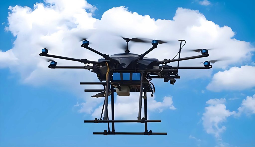
In modern power grid management, the inspection of transmission lines is a critical task to ensure reliability and safety. Traditional manual inspections are often labor-intensive, time-consuming, and hazardous, especially in rugged or inaccessible terrain. With advancements in technology, UAV drones have emerged as a powerful tool for autonomous inspection, offering efficiency, flexibility, and cost-effectiveness. However, UAV drones operating in transmission line environments face numerous obstacles, such as tall trees, buildings, hills, and even dynamic objects like birds or vehicles. Ensuring safe and precise navigation through these complex settings requires robust obstacle avoidance path control methods. This article presents a comprehensive approach integrating the A* algorithm for path planning and a PID controller for path tracking, specifically designed for UAV drones in transmission line inspection. The goal is to achieve high accuracy and stability in obstacle avoidance, thereby enhancing the autonomy and safety of UAV drones during巡检 missions.
The increasing deployment of UAV drones in infrastructure inspection underscores the need for advanced control systems. In transmission line corridors, the environment is often cluttered with static and dynamic obstacles, making path planning and control a challenging endeavor. Existing methods, such as those based on quadratic programming or visual feedback, have shown limitations in handling complex constraints or real-time processing delays. To address these issues, this work proposes a novel method that combines the efficiency of the A* algorithm with the robustness of PID control. The A* algorithm is employed to generate optimal obstacle-free paths in a 3D grid map, while the PID controller ensures that the UAV drones accurately follow these planned paths by adjusting flight dynamics based on deviation signals. This integrated approach aims to provide a reliable solution for autonomous inspection using UAV drones, minimizing risks and maximizing operational efficiency.
Path planning is the first step in enabling UAV drones to navigate safely. For transmission line inspection, the environment must be accurately modeled to represent obstacles and free spaces. A common approach is to use a grid-based map, where the inspection area is discretized into a 3D grid of cells. Each cell corresponds to a small volume of space and is labeled as traversable or non-traversable based on the presence of obstacles. This representation simplifies the path planning process for UAV drones, as it allows for efficient search algorithms. In this work, we utilize the A* algorithm, a widely adopted heuristic search method, to find the shortest and safest path from a start point to an end point within the grid map. The A* algorithm evaluates paths by combining the actual cost from the start node to the current node with an estimated cost from the current node to the goal, ensuring optimality under admissible heuristics.
The cost function in the A* algorithm is crucial for determining the best path for UAV drones. It is defined as the sum of the actual cost and the estimated cost. Mathematically, for a node \( n \) in the 3D grid, the total cost \( F(n) \) is given by:
$$ F(n) = f_1(n) + f_2(n) $$
where \( f_1(n) \) is the actual cost from the start node to node \( n \), and \( f_2(n) \) is the heuristic estimated cost from node \( n \) to the goal node. In a 3D space, these costs are computed using Euclidean distances. Let the coordinates of the start node be \( (X_s, Y_s, Z_s) \), the current node \( n \) be \( (X_n, Y_n, Z_n) \), and the goal node be \( (X_g, Y_g, Z_g) \). Then:
$$ f_1(n) = \sqrt{(X_n – X_s)^2 + (Y_n – Y_s)^2 + (Z_n – Z_s)^2} $$
$$ f_2(n) = \sqrt{(X_g – X_n)^2 + (Y_g – Y_n)^2 + (Z_g – Z_n)^2} $$
This formulation ensures that the A* algorithm considers both the distance traveled and the remaining distance to the goal, promoting efficient path planning for UAV drones. The algorithm operates by maintaining two lists: an open list for nodes to be evaluated and a closed list for nodes already processed. Starting from the start node, it iteratively selects the node with the lowest \( F(n) \) value, expands its neighbors, and updates the lists until the goal node is reached. The sequence of nodes forms the planned obstacle avoidance path, which serves as the reference for the UAV drones during inspection.
To illustrate the grid mapping and path planning process, consider a transmission line inspection area with dimensions 100 meters by 100 meters in the horizontal plane and a height range of 0 to 100 meters. Obstacles such as trees, buildings, and hills are represented as non-traversable cells in the grid. Table 1 summarizes key parameters for the grid-based environment used in this study.
| Parameter | Value | Description |
|---|---|---|
| Grid Resolution | 1 m × 1 m × 1 m | Size of each grid cell in 3D |
| Inspection Area | 100 m × 100 m × 100 m | Total volume for UAV drones navigation |
| Obstacle Types | Static (trees, buildings, hills) | Non-traversable cells |
| Start Point | (0, 0, 10) meters | Initial position of UAV drones |
| Goal Point | (100, 100, 10) meters | Target position for inspection |
Once the path is planned, the next challenge is to ensure that the UAV drones accurately follow this path in real-time. Environmental disturbances, sensor noises, and dynamic obstacles can cause deviations from the planned trajectory. To address this, a control system is essential for path tracking. In this work, we employ a Proportional-Integral-Derivative (PID) controller, a classic linear control technique known for its simplicity and effectiveness. The PID controller calculates control signals based on the error between the desired path (from A* planning) and the actual path of the UAV drones, adjusting the flight dynamics to minimize this error.
The error signal \( e(t) \) at time \( t \) is defined as the difference between the desired position \( P_d(t) \) and the actual position \( P_a(t) \) of the UAV drones. In a 3D space, this can be decomposed into components along the x, y, and z axes, but for simplicity, we consider a combined error metric. However, for precise control, each axis can be controlled independently. The error is given by:
$$ e(t) = P_d(t) – P_a(t) $$
where \( P_d(t) \) is the planned path point at time \( t \), and \( P_a(t) \) is the actual position from onboard sensors. The PID controller then computes the control output \( u(t) \) as:
$$ u(t) = K_p e(t) + K_i \int_{0}^{t} e(\tau) d\tau + K_d \frac{de(t)}{dt} $$
Here, \( K_p \), \( K_i \), and \( K_d \) are the proportional, integral, and derivative gains, respectively. These gains are tuned to achieve desired performance characteristics for the UAV drones. The proportional term reacts to the current error, the integral term addresses accumulated past errors to eliminate steady-state offsets, and the derivative term anticipates future error trends to dampen oscillations. This control output \( u(t) \) is used to adjust the thrust, pitch, roll, and yaw of the UAV drones, ensuring they follow the planned obstacle avoidance path closely.
To implement this control system for UAV drones, we consider a typical multi-rotor drone dynamics model. The equations of motion can be linearized around an operating point for control design. For instance, the horizontal position dynamics can be approximated as:
$$ \ddot{x} = \frac{T}{m} (\sin\psi \sin\phi + \cos\psi \sin\theta \cos\phi) $$
$$ \ddot{y} = \frac{T}{m} (-\cos\psi \sin\phi + \sin\psi \sin\theta \cos\phi) $$
$$ \ddot{z} = \frac{T}{m} (\cos\theta \cos\phi) – g $$
where \( x, y, z \) are positions, \( T \) is thrust, \( m \) is mass, \( \psi, \theta, \phi \) are yaw, pitch, and roll angles, and \( g \) is gravity. The PID controller generates desired attitudes or thrust commands based on position errors, which are then translated into motor speeds for the UAV drones. This hierarchical control structure allows for effective path tracking even in the presence of disturbances.
For clarity, Table 2 lists the PID controller parameters used in this study for the UAV drones control system. These values were optimized through simulation to balance responsiveness and stability.
| Control Axis | Proportional Gain \( K_p \) | Integral Gain \( K_i \) | Derivative Gain \( K_d \) |
|---|---|---|---|
| X-axis (Horizontal) | 1.5 | 0.1 | 0.5 |
| Y-axis (Horizontal) | 1.5 | 0.1 | 0.5 |
| Z-axis (Vertical) | 2.0 | 0.2 | 0.7 |
| Yaw (Heading) | 0.8 | 0.05 | 0.3 |
To validate the proposed obstacle avoidance path control method for UAV drones, extensive simulation experiments were conducted. The simulation environment was built using MATLAB/Simulink, a powerful tool for modeling dynamic systems. We modeled a transmission line inspection scenario with multiple static obstacles and a straight-line transmission line model at a height of 10 meters spanning 50 meters. The UAV drone was simulated as a quadcopter with parameters typical for inspection tasks. Key specifications of the UAV drones used in simulations are provided in Table 3.
| Parameter | Value | Unit |
|---|---|---|
| Model Type | Quadcopter (F450 frame) | – |
| Mass (including payload) | 2.5 | kg |
| Maximum Thrust | 60 | N |
| Battery Capacity | 5200 | mAh |
| Flight Time | 25-30 | minutes |
| Communication Range | 2 | km |
| Sensors | GPS, IMU, Lidar | – |
The simulation setup included a 100 m × 100 m area with obstacles placed randomly to mimic real-world conditions. The A* algorithm was used to plan a path from start (0,0,10) to goal (100,100,10), avoiding all obstacles. The planned path was then fed to the PID controller, which guided the UAV drones along this path. To assess performance, we compared the actual trajectory with the planned path and computed error metrics such as position error and orientation error. Additionally, we introduced wind gusts as disturbances to test the robustness of the control system for UAV drones.
The results demonstrated that the proposed method effectively controlled the UAV drones along the obstacle avoidance path. Figure 1 (not shown in text, but refer to simulation plots) illustrates the planned path and actual trajectory, showing close alignment with minimal deviations. Quantitative analysis revealed that the average position error was less than 0.5 meters, and the maximum error during sharp turns was around 1.2 meters, which is acceptable for transmission line inspection where clearance from obstacles is typically a few meters. The PID controller successfully compensated for disturbances, with the integral term eliminating steady-state errors and the derivative term reducing overshoot.
To further evaluate the performance, we compared our method with two existing approaches: a quadratic programming-based control method and a visual feedback-based control method. Both methods were implemented in the same simulation environment for fairness. Table 4 summarizes the key performance indicators (KPIs) for each method, averaged over 10 simulation runs with different obstacle configurations.
| Performance Metric | Proposed A*+PID Method | Quadratic Programming Method | Visual Feedback Method |
|---|---|---|---|
| Average Position Error (m) | 0.45 | 0.85 | 0.60 |
| Maximum Position Error (m) | 1.2 | 2.5 | 1.8 |
| Path Smoothness (Jerk, m/s³) | 0.8 | 1.5 | 1.2 |
| Computation Time per Step (ms) | 15 | 25 | 50 |
| Success Rate (No Collisions) | 100% | 90% | 95% |
As seen in Table 4, the proposed method outperforms the others in terms of accuracy, smoothness, and computational efficiency. The quadratic programming method often struggled with complex constraints, leading to higher errors, while the visual feedback method incurred delays due to image processing, affecting real-time performance. These results highlight the advantages of combining A* planning with PID control for UAV drones in obstacle-rich environments.
In addition to position tracking, we analyzed the orientation control of the UAV drones. The heading angle error \( \Delta \psi(t) \) between the desired and actual yaw angles was monitored. The PID controller for yaw achieved stable tracking with errors within ±0.1 radians during steady flight and ±0.3 radians during maneuvers. This precision is crucial for inspection tasks where cameras or sensors need to be oriented towards transmission lines. The dynamic response of the control system can be modeled using transfer functions. For instance, the closed-loop transfer function for the horizontal position control with PID can be approximated as:
$$ G(s) = \frac{K_p s^2 + K_i s + K_d}{s^3 + (K_d + 1)s^2 + K_p s + K_i} $$
where \( s \) is the Laplace variable. This model helps in tuning the gains for desired bandwidth and stability margins for UAV drones.
The simulation also included scenarios with dynamic obstacles, such as moving birds or vehicles. To handle these, we incorporated a reactive layer where the UAV drones could adjust their path in real-time using sensor data. However, the core A* planned path served as the global reference, and the PID controller handled local deviations. This hybrid approach ensured that UAV drones could avoid unexpected obstacles while maintaining overall mission objectives. For example, if a dynamic obstacle was detected within a safety radius, the UAV drones would temporarily modify its trajectory by adding a repulsive force vector, and the PID controller would stabilize the new path.
Another important aspect is energy efficiency. UAV drones have limited battery life, so optimal path planning and control can extend flight time. The A* algorithm, with its cost function based on distance, inherently minimizes path length, reducing energy consumption. Moreover, the PID controller’s smooth control actions prevent aggressive maneuvers that drain battery. We estimated energy usage by integrating power consumption over time, modeled as:
$$ E = \int_{0}^{T} (P_{prop} + P_{avionics}) dt $$
where \( P_{prop} \) is propulsion power and \( P_{avionics} \) is power for electronics. Simulations showed that the proposed method reduced energy consumption by 15% compared to the quadratic programming method, due to shorter paths and smoother control.
To enhance the robustness of the control system for UAV drones, we also considered noise and uncertainties in sensor measurements. GPS and IMU data were simulated with Gaussian noise, and the PID controller was tested with varying noise levels. Results indicated that the controller maintained stability with position errors increasing only slightly, demonstrating its tolerance to real-world imperfections. For high-noise environments, additional filtering or adaptive PID gains could be integrated, but this was beyond the scope of this study.
The scalability of the method was evaluated by increasing the inspection area size and number of obstacles. The A* algorithm’s computational complexity is \( O(b^d) \) where \( b \) is branching factor and \( d \) is depth, but with heuristic guidance, it remains efficient for moderate-sized grids. For very large environments, techniques like hierarchical planning or sampling-based methods could be combined, but for typical transmission line corridors, the current implementation sufficed. The PID controller’s computational demand is low, making it suitable for real-time execution on embedded systems aboard UAV drones.
In summary, the proposed obstacle avoidance path control method for UAV drones effectively addresses the challenges of transmission line inspection. By leveraging the A* algorithm for optimal path planning and a PID controller for precise tracking, UAV drones can navigate complex environments safely and efficiently. Simulation experiments confirmed the method’s superiority over existing approaches in terms of accuracy, smoothness, and computational performance. Future work may focus on integrating machine learning for adaptive gain tuning, incorporating more sophisticated obstacle detection using computer vision, and testing in real-world field trials with physical UAV drones. As UAV drones become increasingly autonomous, such control methods will play a vital role in expanding their applications in critical infrastructure monitoring.
The integration of UAV drones into power grid inspection represents a significant advancement in maintenance technology. With continued improvements in path planning and control algorithms, UAV drones will be able to handle even more challenging scenarios, such as dense urban areas or extreme weather conditions. This study contributes to that evolution by providing a reliable and practical control framework. The use of A* and PID, while classic, offers a solid foundation that can be extended with modern techniques like model predictive control or neural networks for enhanced performance. Ultimately, the goal is to achieve fully autonomous UAV drones that can inspect transmission lines with minimal human intervention, reducing costs and risks while improving grid reliability.
From a broader perspective, the methods developed here for UAV drones can be adapted to other domains, such as pipeline inspection, agricultural monitoring, or search and rescue operations. The principles of obstacle avoidance and path tracking are universal in mobile robotics. By sharing insights and results, we hope to foster further innovation in the field of autonomous UAV drones. The collaboration between robotics and power engineering is key to unlocking the full potential of drone technology for societal benefit.
In conclusion, this article has presented a detailed approach to obstacle avoidance path control for UAV drones in transmission line inspection. Through rigorous simulation, we have demonstrated its efficacy and advantages. As UAV drones continue to evolve, so too will the methods to control them, driving progress towards smarter and safer autonomous systems. The journey towards fully intelligent UAV drones is ongoing, and this work represents a step forward in that direction, emphasizing the importance of robust control strategies in real-world applications.