As a researcher in the field of unmanned aerial systems, I have dedicated significant effort to understanding the intricate workings of multirotor drones. These versatile aircraft have revolutionized various industries, from aerial photography to military applications, due to their unique flight capabilities and adaptability. In this article, I will delve into the comprehensive system composition, flight characteristics, and control rigid-body modeling of multirotor drones, drawing from my extensive experience in designing and analyzing these systems. The multirotor drone represents a pinnacle of modern engineering, integrating advanced technologies to achieve stable and efficient flight. I will explore each component in detail, using tables and formulas to summarize key concepts, and provide a foundational framework for further research and development.
The evolution of the multirotor drone has been propelled by advancements in microelectromechanical systems (MEMS), which have miniaturized critical components like gyroscopes, accelerometers, and GPS modules to mere grams. Coupled with the commercialization of lithium-ion batteries offering doubled or tripled energy storage capacity, and improvements in magnetic materials and electronic controls, these innovations have enabled the production of high-torque, compact motors. This progress has made multirotor drones more accessible and capable, fostering their widespread adoption. In my analysis, I focus on the systemic breakdown of a multirotor drone into five primary systems: structural, propulsion, navigation control, telemetry, and payload systems. Each plays a vital role in ensuring the drone’s functionality, and I will elaborate on them with practical insights.
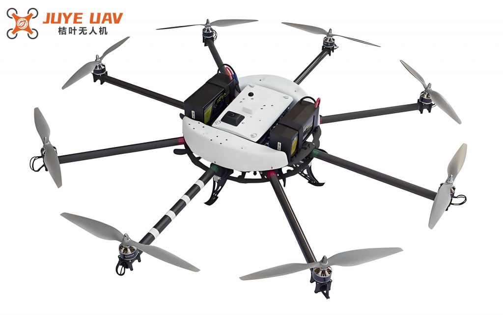
To begin, the structural system of a multirotor drone forms the backbone of the aircraft, comprising the airframe, arms, and landing gear. The airframe serves as the central skeleton, housing various components and enduring forces such as tension, torsion, and shear from the propulsion system. The arms, typically extending from the airframe, provide mounting points for brushless motors and propellers, transmitting lift forces generated by propeller rotation. The landing gear facilitates safe takeoff and landing, ensuring stability during ground operations. In my designs, I prioritize lightweight yet durable materials to enhance agility and payload capacity. The table below summarizes the key components and their functions in the structural system of a multirotor drone.
| Component | Function |
|---|---|
| Airframe | Core skeleton supporting all systems and resisting mechanical stresses |
| Arms | Conduits for lift transmission from propellers to airframe |
| Landing Gear | Ensures stable takeoff and landing operations |
Next, the propulsion system is the heart of the multirotor drone, generating the necessary thrust for flight. It consists of a power battery, electronic speed controllers (ESCs), brushless motors, and propellers. The lithium-ion battery supplies electrical energy, while ESCs convert control signals into three-phase waveforms—square or sine waves—to drive the motors. The brushless motors, upon receiving this power, spin the propellers to produce lift. In my experiments, I have observed that the efficiency of this system directly impacts flight time and stability. For instance, the thrust $T$ generated by a propeller can be modeled as $T = k_T \cdot \omega^2$, where $k_T$ is the thrust coefficient and $\omega$ is the angular velocity. The total lift $L$ for a multirotor drone with $n$ rotors is given by $L = \sum_{i=1}^{n} T_i$, which must balance the gravitational force $mg$ during hover, where $m$ is the mass and $g$ is gravity. The table below outlines the propulsion system components.
| Component | Role |
|---|---|
| Power Battery | Provides electrical energy for motor operation |
| Electronic Speed Controllers | Converts signals to control motor speed and direction |
| Brushless Motors | Drives propellers to generate lift through rotation |
| Propellers | Produces aerodynamic lift via blade motion |
The navigation control system is the brain of the multirotor drone, enabling autonomous flight through precise sensing and computation. It includes a main control unit, an inertial measurement unit (IMU), and a GPS-compass module. The main control unit integrates data from the IMU—which contains a 3-axis accelerometer, 3-axis gyroscope, and barometric altimeter—and the GPS-compass to determine orientation, position, and altitude. Using advanced control algorithms, it calculates flight attitudes and sends commands to the propulsion system. In my implementations, I have used PID controllers to achieve millisecond-level response times for stable hovering and maneuvering. The dynamics can be expressed through equations such as $\dot{\mathbf{p}} = \mathbf{v}$ for position $\mathbf{p}$ and velocity $\mathbf{v}$, and $\dot{\mathbf{R}} = \mathbf{R} \cdot \mathbf{\Omega}_{\times}$ for the rotation matrix $\mathbf{R}$ and skew-symmetric matrix $\mathbf{\Omega}_{\times}$ of angular rates. This system ensures that the multirotor drone can perform complex tasks with high accuracy.
Telemetry systems facilitate real-time data exchange between the multirotor drone and ground stations, supporting remote control and monitoring. These systems consist of air-based and ground-based data links, which can be configured in one-to-one, one-to-many, or many-to-many communication modes. In my fieldwork, I have leveraged these for applications like live video streaming and sensor data transmission, enhancing operational efficiency. The payload system, tailored to specific missions, allows the multirotor drone to carry equipment such as cameras for surveillance, meteorological instruments for atmospheric analysis, or speakers for public address. Military variants may include weapon systems, expanding their utility in defense scenarios. The versatility of the multirotor drone in adapting to various payloads underscores its significance in modern technology.
Moving to flight characteristics, the multirotor drone exhibits distinct behaviors due to its underactuated, nonlinear nature. It operates in six degrees of freedom: three translational and three rotational. Key flight modes include hover, vertical ascent, vertical descent, lateral flight, climb, descent, and turning. During hover, the multirotor drone maintains a fixed position and altitude, with propeller lift $L$ equaling weight $mg$, and motor speeds adjusting minutely to counteract disturbances like wind. This is described by the force balance $L = mg$, where $L = \sum T_i$. For vertical ascent, $L > mg$, resulting in upward acceleration, while for descent, $L < mg$, causing downward motion. However, descent speeds are often limited to avoid instability from vortex ring state, where airflow recirculation reduces lift. The maximum ascent speed $v_{\text{max, up}}$ can be derived from $m \dot{v} = L – mg – D$, with $D$ as drag, whereas descent speed $v_{\text{max, down}}$ is constrained by safety considerations.
Lateral flight involves rolling or pitching the multirotor drone to generate horizontal thrust components, overcoming drag forces. For example, in forward flight, a pitch angle $\theta$ is introduced, and the equations of motion include $m \dot{v}_x = L \sin\theta – D_x$, where $D_x$ is the drag in the x-direction. Climb and descent combine vertical and horizontal motions, with flight path angles $\gamma$ ranging from 0° to 90°. The equilibrium speed in climb occurs when $L \cos\gamma = mg$ and $L \sin\gamma = D$, optimizing performance. Turning maneuvers include point turns, coordinated turns, and adaptive turns, each affecting the trajectory differently. Point turns involve stopping to rotate, coordinated turns maintain speed with wider arcs, and adaptive turns reduce speed for tighter turns. These behaviors highlight the agility of the multirotor drone in complex environments.
To model the flight dynamics, I employ a control rigid-body approach, assuming the multirotor drone is a symmetric, rigid body with constant mass and inertia, and that forces act only at the center of gravity. Using inertial (ground) and body-fixed coordinates, I define the ground frame $O_eX_eY_eZ_e$ with $Z_e$ downward, and the body frame $O_bX_bY_bZ_b$ fixed to the drone. The rotation matrix $\mathbf{R}_b^e$ from body to ground frames is given by:
$$ \mathbf{R}_b^e = \begin{bmatrix} \cos\theta \cos\psi & \sin\phi \sin\theta \cos\psi – \cos\phi \sin\psi & \cos\phi \sin\theta \cos\psi + \sin\phi \sin\psi \\ \cos\theta \sin\psi & \sin\phi \sin\theta \sin\psi + \cos\phi \cos\psi & \cos\phi \sin\theta \sin\psi – \sin\phi \cos\psi \\ -\sin\theta & \sin\phi \cos\theta & \cos\phi \cos\theta \end{bmatrix} $$
where $\phi$, $\theta$, and $\psi$ are roll, pitch, and yaw Euler angles. The position dynamics follow Newton’s second law: $m \ddot{\mathbf{p}} = \mathbf{R}_b^e \cdot \mathbf{F}_b + m \mathbf{g}$, with $\mathbf{F}_b = [0, 0, -T]^T$ as the thrust vector in body frame, and $\mathbf{g} = [0, 0, g]^T$. This expands to:
$$ \begin{aligned} m \ddot{x} &= T (\sin\phi \sin\psi + \cos\phi \cos\psi \sin\theta) \\ m \ddot{y} &= T (\cos\phi \sin\theta \sin\psi – \sin\phi \cos\psi) \\ m \ddot{z} &= T \cos\phi \cos\theta – mg \end{aligned} $$
Attitude dynamics are derived from Euler’s equations: $\mathbf{I} \dot{\boldsymbol{\omega}} + \boldsymbol{\omega} \times \mathbf{I} \boldsymbol{\omega} = \boldsymbol{\tau}$, where $\mathbf{I}$ is the inertia matrix, $\boldsymbol{\omega} = [p, q, r]^T$ is the angular velocity in body frame, and $\boldsymbol{\tau} = [\tau_\phi, \tau_\theta, \tau_\psi]^T$ is the torque vector. For a quadrotor, the torques relate to rotor speeds $\omega_i$ as $\tau_\phi = l k_T (\omega_4^2 – \omega_2^2)$, $\tau_\theta = l k_T (\omega_3^2 – \omega_1^2)$, and $\tau_\psi = k_Q (\omega_1^2 + \omega_3^2 – \omega_2^2 – \omega_4^2)$, with $l$ as arm length and $k_Q$ as drag coefficient.
The kinematics model connects velocities to positions and attitudes: $\dot{\mathbf{p}} = \mathbf{v}$ and $\dot{\boldsymbol{\Theta}} = \mathbf{E} \cdot \boldsymbol{\omega}$, where $\boldsymbol{\Theta} = [\phi, \theta, \psi]^T$ and $\mathbf{E}$ is the transformation matrix. For small angles, $\mathbf{E} \approx \mathbf{I}$, simplifying to $\dot{\boldsymbol{\Theta}} \approx \boldsymbol{\omega}$. Combining dynamics and kinematics, the full nonlinear model for a multirotor drone is:
$$ \begin{aligned} \ddot{\mathbf{p}} &= \frac{1}{m} \mathbf{R}_b^e \mathbf{F}_b + \mathbf{g} \\ \dot{\boldsymbol{\omega}} &= \mathbf{I}^{-1} (\boldsymbol{\tau} – \boldsymbol{\omega} \times \mathbf{I} \boldsymbol{\omega}) \\ \dot{\mathbf{p}} &= \mathbf{v} \\ \dot{\boldsymbol{\Theta}} &= \mathbf{E} \boldsymbol{\omega} \end{aligned} $$
This model facilitates simulation and control design for multirotor drones, enabling precision in tasks like path following and disturbance rejection. In my work, I have applied this to optimize flight controllers, ensuring robust performance under varying conditions. The table below summarizes the key variables in the control model.
| Variable | Description |
|---|---|
| $\mathbf{p}$ | Position vector in ground frame |
| $\mathbf{v}$ | Velocity vector in ground frame |
| $\boldsymbol{\Theta}$ | Euler angles (roll, pitch, yaw) |
| $\boldsymbol{\omega}$ | Angular velocity in body frame |
| $T$ | Total thrust from propellers |
| $\boldsymbol{\tau}$ | Torque vector in body frame |
| $\mathbf{I}$ | Inertia matrix |
| $\mathbf{R}_b^e$ | Rotation matrix from body to ground frame |
In conclusion, the multirotor drone represents a complex yet elegantly designed system that integrates multiple disciplines. Through detailed analysis of its systems and flight characteristics, and the development of a control rigid-body model, I have provided a comprehensive framework that aids in the design and optimization of these aircraft. This approach not only enhances understanding but also drives innovation in multirotor drone technology, paving the way for future advancements in autonomous flight and application-specific adaptations. The multirotor drone continues to evolve, and I am confident that this foundation will support ongoing research and practical implementations across various fields.