
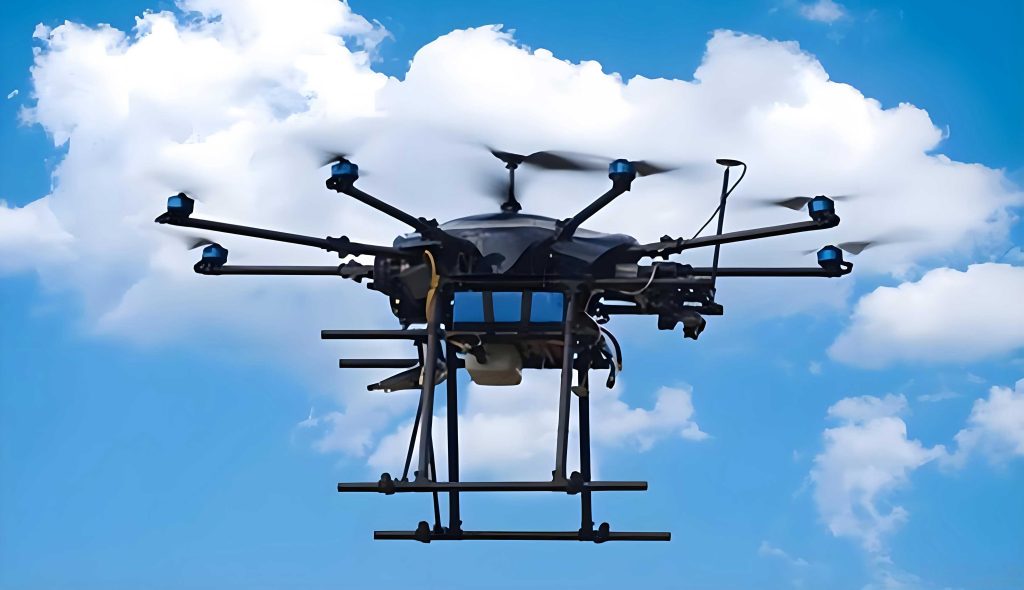
As society continues to evolve, the variety of special aircraft and UAV drones has grown significantly. Different mission payloads require dedicated management devices tailored to their specific operational needs. When a single aircraft, especially a UAV drone, must execute multiple concurrent missions, it becomes essential to uniformly manage and dispatch all carried payloads. This demands advanced technologies to streamline the process, enabling UAV drones to perform their tasks more effectively. In this article, I present a comprehensive design and implementation approach for a multi-mission management computer tailored for special aircraft and UAV drones, covering system architecture, hardware modules, software frameworks, modularity, and reliability considerations.
1. Design Philosophy of the Onboard Mission Management Computer
The mission payload system of special aircraft and UAV drones is inherently complex. When a single UAV drone is equipped with multiple payloads to perform various tasks simultaneously, a unified system architecture is required. Typical mission payloads include aerial cameras, multi‑function radars, laser fluorescence detectors, and corresponding display‑control devices. However, due to the limited bandwidth of data links, only one or two payloads’ target information can be transmitted at a time. To overcome this bottleneck, an onboard mission management computer (OMMC) is introduced. The OMMC must satisfy five critical requirements:
- Interface conversion: The output interfaces of mission payloads often mismatch the data terminal interfaces of the aircraft; the OMMC must convert between them.
- Payload scheduling and integrated management: When a UAV drone carries multiple payloads, the OMMC coordinates and manages them to ensure efficient mission execution.
- Unified monitor output: The OMMC provides a single output interface for onboard monitors, enabling seamless surveillance of target information from all payloads.
- Control input: It supplies corresponding input interfaces for the cockpit control devices that issue commands to each payload.
- Data recording and retrieval: The OMMC must record and allow retrieval of mission payload target data.
2. Working Principle of the Onboard Mission Management Computer
Internally, the OMMC consists of several functional modules: the computer motherboard module, data storage module, power module, etc. The computer module acts as the main controller, communicating with other modules via high‑speed serial buses. The core workflow involves receiving payload data and control signals, processing them, and distributing them to the appropriate subsystems. The system’s operational flow can be summarized by the following fundamental data‑rate equation:
$$ R_{\text{total}} = \sum_{i=1}^{n} R_{\text{payload}, i} $$
where $R_{\text{total}}$ is the total data throughput required and $R_{\text{payload}, i}$ is the data rate of the $i$‑th payload. The OMMC ensures that $R_{\text{total}}$ does not exceed the available internal bus bandwidth $B_{\text{bus}}$:
$$ R_{\text{total}} \le B_{\text{bus}} $$
This constraint drives the selection of high‑speed interconnects such as PCIe, USB 3.0, and Gigabit Ethernet.
3. Hardware Design of the Onboard Mission Management Computer
3.1 Payload Data Interface Module
This module handles format conversion of mission payload target data and forwards status information. It comprises three main components: FPGA, interface conversion logic, and DDR memory. The FPGA performs real‑time data parsing and protocol translation. The interface conversion block adapts various payload output standards (e.g., Camera Link, GigE Vision, Analog Video) to a unified internal format. DDR memory buffers transient data bursts to prevent loss. Key performance parameters are listed in Table 1.
| Parameter | Value | Remarks |
|---|---|---|
| Number of input channels | 4 | Supports up to 4 payloads simultaneously |
| Input data rate (per channel) | ≤ 3.2 Gbps | Based on Camera Link Full configuration |
| Output data rate (internal bus) | ≤ 12.8 Gbps | Aggregate via PCIe Gen2 x4 |
| FPGA logic cells | 150K | Xilinx Kintex‑7 series |
| DDR memory | 1 GB DDR3 | 1333 MHz |
3.2 Data Transmission Interface Module
This module connects directly to the onboard data terminal. It receives and forwards mission payload target data and status information, and processes control commands from the data terminal. The module also implements error correction encoding to ensure link reliability. Figure 1 below shows the module’s hardware block diagram.
The data transmission interface supports dual‑redundant Ethernet (1000BASE‑T) and two USB 3.0 ports for external connectivity. The module’s key specifications are provided in Table 2.
| Parameter | Value | Remarks |
|---|---|---|
| Ethernet ports | 2 × 1000BASE‑T | Redundant for fault tolerance |
| USB 3.0 ports | 2 × USB 3.0 | Up to 5 Gbps each |
| RS‑422/485 | 4 channels | For legacy payload control |
| Data throughput | Up to 10 Gbps | Aggregate with proper flow control |
3.3 Data Storage Module
Storage of mission payload target data and status information is realized via PCIe bus access to an SSD. The data can be read out using the computer motherboard’s USB 3.0 interface. The storage capacity is scalable; typical configuration uses a 512 GB M.2 NVMe SSD. The storage write speed must match the incoming data rate:
$$ v_{\text{write}} \ge R_{\text{total}} $$
where $v_{\text{write}}$ is the sustained write speed of the SSD. For a configuration with four payloads each at 3.2 Gbps, $R_{\text{total}} = 12.8\,\text{Gbps} = 1.6\,\text{GB/s}$, which is achievable with modern NVMe drives (≥ 2.0 GB/s). Table 3 summarizes the storage module.
| Parameter | Value | Remarks |
|---|---|---|
| Storage medium | M.2 NVMe SSD | 512 GB / 1 TB / 2 TB options |
| Interface | PCIe Gen3 x4 | Theoretical 32 Gbps |
| Sustained write speed | ≥ 2.0 GB/s | Ensures non‑blocking recording |
| Data retrieval | USB 3.0 or Ethernet | External download |
3.4 VPX Computer Motherboard
The VPX computer motherboard is the core processing unit. It receives payload target data and status information from the data interface module, processes payload control commands, and runs the mission payload display‑control software. The motherboard also manages data transfer to the storage module via PCIe, and exports stored data through its USB 3.0 interface. The motherboard features an Intel Core i7‑6700 processor (or equivalent ruggedized CPU), 16 GB DDR4 RAM, and a dedicated GPU for video processing. The computational load for real‑time target tracking can be modeled as:
$$ T_{\text{process}} = \frac{N_{\text{frames}} \times P_{\text{frame}}}{f_{\text{CPU}}} $$
where $N_{\text{frames}}$ is the number of frames per second, $P_{\text{frame}}$ is the processing cycles per frame, and $f_{\text{CPU}}$ is the CPU clock frequency. For typical surveillance data, this remains well within the motherboard’s capacity.
3.5 VPX Backplane
The VPX backplane provides physical connectivity for all modules. It routes internal signals and connects the modules’ external interfaces to the aircraft’s avionics connectors via flexible circuit boards. Since the computer motherboard provides only one USB 2.0 and one USB 3.0 port, but the system requires two of each for external interfaces, the backplane incorporates a USB hub controller to expand one USB 3.0 port into two ports. Similarly, the single 1000‑Mbit network interface is expanded to two via an onboard Ethernet switch. Two spare module slots are also available on the backplane; these are connected to the motherboard’s remaining PCIe lanes to support future expansion modules (e.g., additional storage or specialized I/O). The backplane’s power distribution follows a star topology, with each module receiving regulated +12 V, +5 V, +3.3 V supplies. The total power consumption of the OMMC is given by:
$$ P_{\text{total}} = P_{\text{MB}} + P_{\text{storage}} + P_{\text{payload\_if}} + P_{\text{tx\_if}} + P_{\text{backplane\_overhead}} $$
where typical values are: $P_{\text{MB}} \approx 45\,\text{W}$, $P_{\text{storage}} \approx 5\,\text{W}$, $P_{\text{payload\_if}} \approx 12\,\text{W}$, $P_{\text{tx\_if}} \approx 8\,\text{W}$, $P_{\text{backplane\_overhead}} \approx 2\,\text{W}$, yielding $P_{\text{total}} \approx 72\,\text{W}$.
3.6 Power Supply Module
The power supply module delivers clean, regulated power to all submodules. Due to the motherboard’s higher consumption, it uses a dedicated power supply unit (PSU). The other modules share a second PSU. Each PSU input is protected by a fuse and includes an EMI filter and transient protection circuit. The power module is designed to meet MIL‑STD‑704 (aircraft power quality) and DO‑160 requirements. Efficiency $\eta$ must be high to minimize heat dissipation:
$$ \eta = \frac{P_{\text{out}}}{P_{\text{in}}} \ge 85\% $$
Table 4 provides the power specifications.
| Parameter | PSU 1 (Motherboard) | PSU 2 (Other modules) |
|---|---|---|
| Input voltage | 28 V DC (18‑36 V range) | 28 V DC |
| Output voltage | +12 V / 5 A, +5 V / 3 A, +3.3 V / 2 A | +12 V / 8 A, +5 V / 5 A, +3.3 V / 3 A |
| Maximum output power | 80 W | 120 W |
| Efficiency | > 87% | > 85% |
| Protection | Overvoltage, overcurrent, reverse polarity | Same |
4. Software Design of the Onboard Mission Management Computer
4.1 Main Control Software
The main control software is developed using Qt framework in C++ under Windows 10 (or a real‑time OS for critical UAV drones). It provides a human‑machine interface (HMI) for mission planning, payload status display, and command issuance. User commands are transferred to the FPGA’s PCIe interface via the PCIe bus driver. The FPGA firmware then dispatches these commands to internal submodules. The communication protocol between the main software and FPGA is based on a custom packet structure with CRC‑32 error detection. The software architecture is modular, comprising the following components as shown in Table 5.
| Module | Function | Technology |
|---|---|---|
| User Interface (UI) | Mission configuration, payload control, visualization | Qt Widgets / QML |
| Command & Control (C2) | Encapsulate commands, send to FPGA, receive acknowledgements | C++ / PCIe driver API |
| Data Recording | Manage streaming to SSD, file indexing, playback | Asynchronous I/O, SQLite metadata |
| Health Monitor | Monitor module temperatures, voltages, link status | Sensor polling, event‑driven alerts |
| Network Interface | Communicate with ground control station via link | TCP/UDP sockets, custom protocol |
4.2 FPGA Software
The FPGA firmware handles real‑time processing of video data from multiple payloads. It performs input capture, format conversion (e.g., decoding Camera Link, converting to LVDS), scaling, and output encoding (e.g., HDMI or SDI for the cockpit monitor). The data flow through the FPGA can be represented as a pipeline:
$$ \text{Input}_{k} \xrightarrow{\text{format\_convert}} \text{Buffer} \xrightarrow{\text{scaler}} \text{MUX} \xrightarrow{\text{output\_encoder}} \text{Output}_{k} $$
where $k$ indexes the payload channel. The selection of active channels is controlled by the main CPU via PCIe registers. The FPGA also implements a watchdog timer to reset the system if communication with the main CPU is lost for more than 200 ms.
5. Generalization, Serialization, and Modularization (Three‑Standard Design)
The OMMC is designed with a strong emphasis on modularity, serialization, and standardization (often referred to as “three‑standard design” in the industry). This approach simplifies fault detection and isolation, and allows rapid interchange of mission payload data modules. Key aspects include:
- Functional Modularity: Each hardware module (payload interface, transmission interface, storage, motherboard, power) is a self‑contained unit with standard connectors (VPX, USB, Ethernet). This enables quick replacement without re‑cabling.
- Series of Performance Options: For the VPX computer motherboard, multiple variants are available, ranging from low‑power i5 for basic missions to high‑performance Xeon for heavy processing. Similarly, storage modules can be ordered with 256 GB, 512 GB, 1 TB, or 2 TB SSDs. This allows tailoring the OMMC to different UAV drone platforms and mission profiles.
- Combinatorial Upgrades: Because the system is modular, upgrading one module (e.g., replacing the data interface module with a newer FPGA design) does not affect other modules. Furthermore, modules from different performance tiers can be combined to create a new system that meets specific cost‑performance targets. This reusability accelerates development of derivative systems for various special aircraft and UAV drones.
6. Six‑Characteristic Design (Reliability, Safety, Maintainability, Testability, Supportability, Environmental Adaptability)
The OMMC’s design incorporates six critical characteristics, often abbreviated as “R‑M‑S‑T‑S‑E” in military and aerospace contexts. I detail each below.
6.1 Reliability
Reliability is achieved through mature technology and proven manufacturing processes. All circuits use low‑power components operating at derated stress levels. Each module is equipped with a heat sink (or forced‑air cooling) to maintain junction temperatures below 85°C. The chassis is locked to the aircraft ground via a dedicated grounding strap to prevent electrostatic discharge. Manufacturing defects were minimized by implementing IPC‑Class 3 standards for soldering and conformal coating. Predicted Mean Time Between Failures (MTBF) is calculated using MIL‑HDBK‑217F:
$$ \text{MTBF} = \frac{1}{\sum_{i} \lambda_i} $$
where $\lambda_i$ is the failure rate of the $i$‑th component under its actual stress. The computed MTBF for the entire OMMC exceeds 20,000 hours.
6.2 Safety
The OMMC employs only low‑voltage digital and analog circuits (max 12 V), eliminating shock hazards to personnel. All exposed metal parts are connected to chassis ground. Power inputs are protected by fuses and transient suppressors. The software detects anomalous conditions (e.g., overtemperature, loss of communication) and gracefully shuts down non‑critical functions or issues a warning to the UAV drone ground station.
6.3 Maintainability
Modular design ensures that any faulty module can be swapped out rapidly. All connectors are keyed and color‑coded to prevent mis‑insertion. The chassis uses quick‑release fasteners. The average repair time is under 30 minutes for a trained technician. Maintenance manuals include step‑by‑step replacement procedures with error‑code tables.
6.4 Testability
Every module features built‑in status LEDs indicating power‑on, activity, and fault conditions. At system power‑up, a built‑in test (BIT) sequence is executed autonomously. The BIT verifies internal memory, bus connectivity, and communication with all payload interfaces. Results are displayed on the HMI; if a test fails, the system halts and displays a fault code. Additionally, each module supports boundary‑scan (JTAG) for deeper diagnostics during depot maintenance.
6.5 Supportability
Before deployment, each OMMC undergoes a 72‑hour burn‑in test with simulated mission loads. Spare modules (one each of the five main types) are supplied with every system. A support kit includes programming cables, a diagnostic laptop with custom software, and a set of common replacement parts. Technical support is available through the manufacturer’s helpdesk with a 4‑hour response time.
6.6 Environmental Adaptability
The OMMC is qualified to operate over a temperature range of –40°C to +70°C (non‑condensing). For humidity, it meets 95% RH at 35°C per DO‑160. The chassis is sealed against salt fog and fungal growth (using conformal coating and gaskets). Vibration and shock resistance are designed to RTCA/DO‑160 categories S (helicopter) and M (fixed‑wing). An acceleration of up to 6 g in any axis is tolerated without performance degradation. These capabilities allow the OMMC to be installed in a wide range of special aircraft and UAV drones, from high‑altitude long‑endurance (HALE) platforms to agile tactical drones.
7. Conclusion
The design and implementation of a multi‑mission management computer for special aircraft and UAV drones is a challenging yet essential task. Through careful hardware partitioning, robust software architecture, and rigorous adherence to modularity and six‑characteristic design principles, the OMMC delivers a reliable, flexible, and maintainable solution. As the capabilities of UAV drones continue to expand, the need for even more integrated and intelligent mission management systems will grow. Future work will focus on incorporating artificial intelligence for autonomous payload scheduling, enhancing cybersecurity for data links, and further reducing power consumption to extend mission endurance. The approach presented here provides a solid foundation for next‑generation mission management computers in the evolving landscape of unmanned aerial systems.