
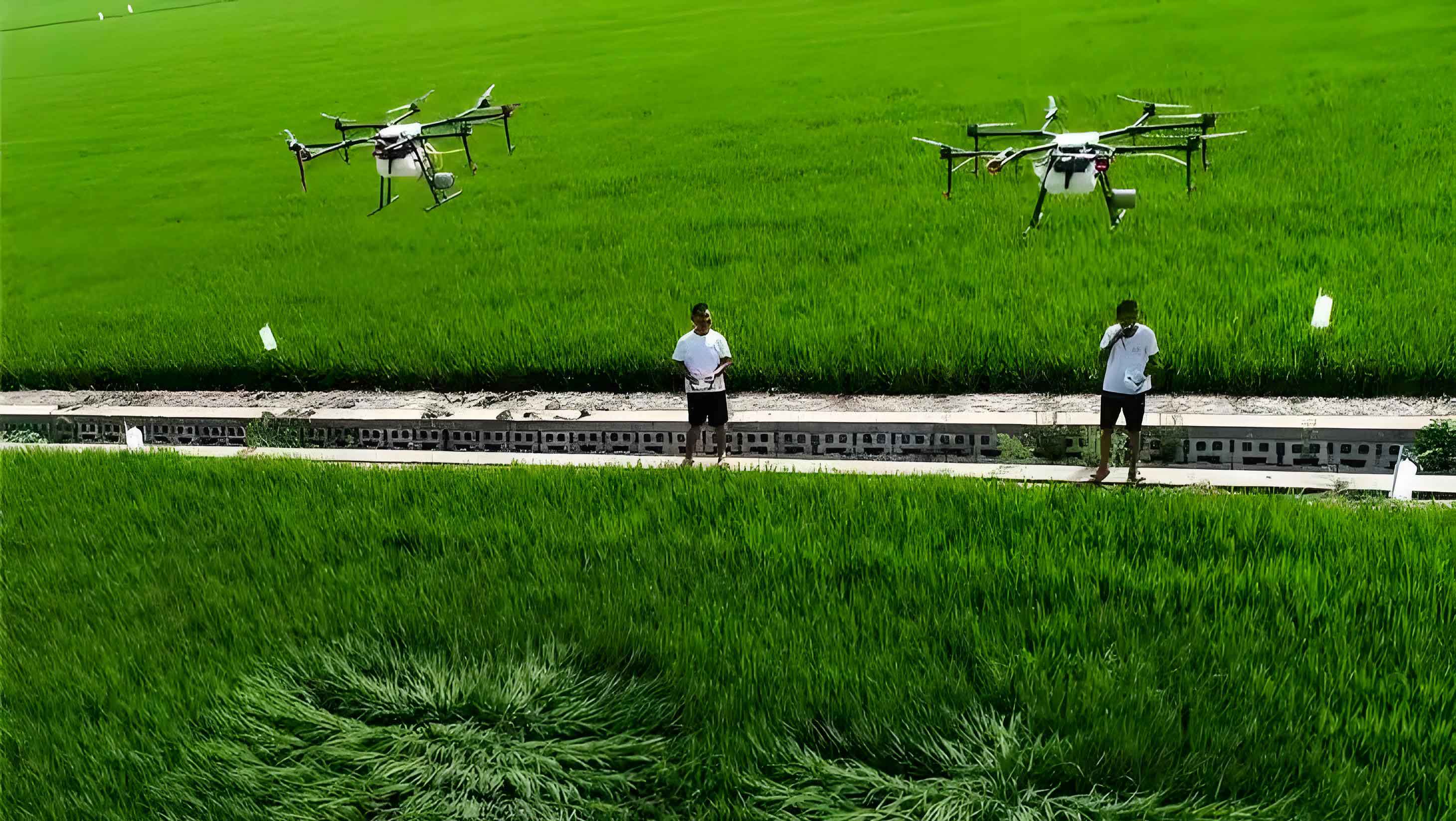
The continuous advancement of the national economy has catalyzed remarkable achievements in the industrial sector. As a major agricultural nation possessing 1.8 billion mu of fundamental farmland, China is witnessing a growing emphasis on the application of agricultural drones, propelled by the broader development of civil unmanned aerial vehicles and the ongoing exploration of their application domains. Among various launch methods, the rocket-boosted zero-length launch offers distinct advantages, including a simple launch apparatus, minimal ground footprint, low initial investment, and reduced susceptibility to launch environment variations. It also fulfills requirements for flexibility and mobility. However, this launch process inherently carries certain risks. While existing research has investigated the launch phase of drones, the modeling and simulation efforts have often incorporated only a subset of influential factors.
This article addresses the launch process of an agricultural drone, considering a comprehensive set of factors that influence its launch. The primary focus is on investigating the attitude variations during the launch phase under different launch conditions. During launch, any change in launch-related parameters can affect the drone’s launch attitude and flight performance. Therefore, through simulation studies of varying parameters, we aim to derive the trend and sensitivity of how different parameter changes impact launch performance. This analysis provides a crucial foundation for designing launch “margins” and ensuring the safe launch of agricultural drones.
1. Mathematical Model for Agricultural Drone Zero-Length Launch
Numerous factors influence the launch process of an agricultural drone, such as variations in thrust misalignment, booster thrust, launch angle, and different launch environments. Due to the presence of these diverse influencing factors, it is insufficient to simplify the analysis by considering only the longitudinal launch scenario. Consequently, a six-degree-of-freedom (6-DOF) nonlinear dynamic model incorporating all significant terms is established for this study.
1.1 Dynamic Model of the Agricultural Drone
To ensure the authenticity and reliability of the research, the influence of wind speed in the launch environment cannot be neglected when establishing the 6-DOF equations of motion for the agricultural drone. The relationship is given by \(\mathbf{V_K} = \mathbf{V_A} + \mathbf{V_W}\), where \(\mathbf{V_K}\) is the ground velocity, \(\mathbf{V_A}\) is the airspeed, and \(\mathbf{V_W}\) is the wind velocity vector. The dynamic equations established in the drone’s body coordinate system are as follows:
$$
\begin{aligned}
m(\dot{u}_K + q w_K – r v_K) &= F_x \\
m(\dot{v}_K + r u_K – p w_K) &= F_y \\
m(\dot{w}_K + p v_K – q u_K) &= F_z \\
J_x \dot{p} – J_{zx}(\dot{r} + p q) – J_{xy}(\dot{q} – r p) + (J_z – J_y)q r – J_{yz}(q^2 – r^2) &= M_x \\
J_y \dot{q} – J_{xy}(\dot{p} + q r) – J_{yz}(\dot{r} – p q) + (J_x – J_z)r p – J_{zx}(r^2 – p^2) &= M_y \\
J_z \dot{r} – J_{yz}(\dot{q} + r p) – J_{zx}(\dot{p} – q r) + (J_y – J_x)p q – J_{xy}(p^2 – q^2) &= M_z
\end{aligned}
$$
where \(u_K, v_K, w_K\) are the components of the ground velocity vector \(\mathbf{V_K}\) in the body coordinate system; \(p, q, r\) are the angular rates (i.e., angular velocities about the body axes); \(J_x, J_y, J_z\) are the moments of inertia; and \(J_{xy}, J_{yz}, J_{zx}\) are the products of inertia. For the face-symmetric configuration of the studied agricultural drone, \(J_{xy}=J_{yz}=0\).
The kinematic equations are:
$$
\begin{aligned}
\dot{\phi} &= p + (q \sin\phi + r \cos\phi) \tan\theta \\
\dot{\theta} &= q \cos\phi – r \sin\phi \\
\dot{\psi} &= (q \sin\phi + r \cos\phi) \sec\theta
\end{aligned}
$$
where \(\psi, \theta, \phi\) are the drone’s attitude angles (yaw, pitch, and roll, respectively). The relationship between ground velocity components in the body frame \((u_K, v_K, w_K)\) and the Earth-fixed frame \((u_{Kg}, v_{Kg}, w_{Kg})\) is given by the transformation matrix \(L_{EB}\):
$$
\begin{bmatrix} u_{Kg} \\ v_{Kg} \\ w_{Kg} \end{bmatrix} = L_{EB} \begin{bmatrix} u_K \\ v_K \\ w_K \end{bmatrix}
$$
| Symbol | Description | Unit |
|---|---|---|
| \(u_K, v_K, w_K\) | Body-axis components of ground velocity \(\mathbf{V_K}\) | m/s |
| \(p, q, r\) | Roll, pitch, yaw angular rates | rad/s |
| \(\phi, \theta, \psi\) | Roll, pitch, yaw angles | rad |
| \(J_x, J_y, J_z\) | Moments of inertia | kg·m² |
| \(m\) | Mass of the agricultural drone | kg |
| \(F_x, F_y, F_z\) | Total external force components in body axes | N |
| \(M_x, M_y, M_z\) | Total external moment components in body axes | N·m |
1.2 External Force System and Mathematical Model
A safe launch for the agricultural drone requires sufficient altitude and airspeed. This demands adequate thrust during launch, which is achieved by employing a rocket booster and the drone’s main engine working simultaneously. Typically, the booster rocket is installed according to the structural characteristics of the agricultural drone, with common configurations including a single ventral booster, a single dorsal booster, or symmetrical dual boosters on the fuselage sides.
During launch, due to the high thrust of the rocket booster and the continuous operation of the engine, installation angle errors and center-of-gravity (CG) position variations arising from production and assembly can generate significant thrust misalignment moments. These moments may compromise the safety and stability of the agricultural drone launch. Therefore, when formulating the mathematical model for external forces, changes in installation angles and CG position must be reflected. The resultant force and moment equations are:
$$
\begin{aligned}
\mathbf{F} &= \mathbf{F}_r + \mathbf{F}_e + \mathbf{A} + \mathbf{G} \\
\mathbf{M} &= \mathbf{M}_r + \mathbf{M}_e + \mathbf{M}_a
\end{aligned}
$$
where \(\mathbf{F}\) is the total external force, \(\mathbf{F}_r\) is the rocket booster thrust, \(\mathbf{F}_e\) is the engine thrust, \(\mathbf{A}\) is the aerodynamic force, \(\mathbf{G}\) is the gravitational force, \(\mathbf{M}\) is the total external moment, \(\mathbf{M}_r\) is the moment from the booster thrust, \(\mathbf{M}_e\) is the moment from the engine thrust, and \(\mathbf{M}_a\) is the aerodynamic moment.
The rocket booster thrust \(\mathbf{F}_r\) in component form, accounting for longitudinal (\(\delta_\alpha\)) and lateral (\(\delta_\beta\)) installation angles relative to the body X-axis, is:
$$
\mathbf{F}_r = F_r \begin{bmatrix} \cos\delta_\alpha \cos\delta_\beta \\ -\cos\delta_\alpha \sin\delta_\beta \\ -\sin\delta_\alpha \end{bmatrix}
$$
where \(F_r\) is the magnitude of the booster thrust.
The moments generated by the booster and the main engine have similar component forms, determined by the thrust vector and its point of application relative to the CG \((x_{cg}, y_{cg}, z_{cg})\). For a thrust component \(\mathbf{F}_i = [F_{ix}, F_{iy}, F_{iz}]^T\) applied at point \((x_i, y_i, z_i)\), the induced moment is:
$$
\mathbf{M}_i = \begin{bmatrix} (y_i – y_{cg})F_{iz} – (z_i – z_{cg})F_{iy} \\ (z_i – z_{cg})F_{ix} – (x_i – x_{cg})F_{iz} \\ (x_i – x_{cg})F_{iy} – (y_i – y_{cg})F_{ix} \end{bmatrix}
$$
This formulation explicitly captures the moments arising from thrust misalignment due to CG shifts or installation errors, which are critical for assessing the launch stability of the agricultural drone.
1.3 Aerodynamic Coefficients and Supplementary Equations
Based on wind tunnel test data, the aerodynamic force and moment coefficients are fitted numerically. During the fitting process, the influence of lateral-directional parameters on the aerodynamic coefficients is taken into account to capture coupling effects. To close the complete mathematical model, supplementary equations relating flight velocity components to angle of attack (\(\alpha\)) and sideslip angle (\(\beta\)) are required:
$$
\begin{aligned}
\alpha &= \arctan\left(\frac{w}{u}\right) \\
\beta &= \arcsin\left(\frac{v}{V_A}\right) \\
V_A &= \sqrt{u^2 + v^2 + w^2}
\end{aligned}
$$
where \(u, v, w\) are the components of the airspeed vector \(\mathbf{V_A}\) in the body coordinate system. The aerodynamic forces and moments are then calculated using standard coefficient forms:
$$
\begin{aligned}
A_x &= \bar{q} S C_X(\alpha, \beta, \ldots), \quad &A_y &= \bar{q} S C_Y(\alpha, \beta, \ldots), \quad &A_z &= \bar{q} S C_Z(\alpha, \beta, \ldots) \\
M_{a,x} &= \bar{q} S b C_l(\alpha, \beta, p, r, \ldots), \quad &M_{a,y} &= \bar{q} S \bar{c} C_m(\alpha, \beta, q, \ldots), \quad &M_{a,z} &= \bar{q} S b C_n(\alpha, \beta, p, r, \ldots)
\end{aligned}
$$
where \(\bar{q} = \frac{1}{2} \rho V_A^2\) is the dynamic pressure, \(S\) is the reference area, \(b\) is the wingspan, \(\bar{c}\) is the mean aerodynamic chord, and \(C_*\) are the dimensionless aerodynamic coefficients.
2. Simulation Model and Results for the Agricultural Drone
2.1 Simulation Model Architecture
This study utilizes the MATLAB/Simulink environment to construct a simulation platform based on the derived complete mathematical model. The core simulation workflow is illustrated below. The model integrates the 6-DOF dynamics, external force calculations (including detailed thrust misalignment models), aerodynamics lookup tables, and environmental conditions. The state variables are propagated using a numerical integration solver (e.g., ODE45) to simulate the launch trajectory and attitude evolution of the agricultural drone from rail separation through booster burnout and initial climb.
Simulation Process Workflow:
1. Initialization: Set initial conditions (launch angle, position, zero velocity), drone parameters (mass, inertia, CG), and launch parameters (booster thrust profile \(F_r(t)\), engine thrust \(F_e\), misalignment values \((\delta_\alpha, \delta_\beta, y_i, z_i)\), wind \(\mathbf{V_W}\)).
2. Force & Moment Calculation:
– Calculate gravitational force \(\mathbf{G}\) in body axes.
– Calculate booster and engine thrust vectors and moments based on current misalignment and CG.
– Compute airspeed \(\mathbf{V_A} = \mathbf{V_K} – \mathbf{V_W}\).
– Determine \(\alpha\) and \(\beta\).
– Look up/interpolate aerodynamic coefficients \(C_X, C_Y, C_Z, C_l, C_m, C_n\) based on current \(\alpha, \beta, p, q, r,\) etc.
– Compute aerodynamic forces \(\mathbf{A}\) and moments \(\mathbf{M}_a\).
3. State Derivatives:
– Assemble total forces \(\mathbf{F}\) and moments \(\mathbf{M}\).
– Solve the 6-DOF dynamic equations (Eq. 1) for translational \((\dot{u}_K, \dot{v}_K, \dot{w}_K)\) and rotational \((\dot{p}, \dot{q}, \dot{r})\) accelerations.
– Calculate kinematic derivatives \((\dot{\phi}, \dot{\theta}, \dot{\psi})\) from Eq. (2).
– Calculate navigation derivatives (position in Earth frame).
4. Numerical Integration: Feed the derivatives to the ODE solver to update the state vector for the next time step.
5. Termination Check: Stop simulation if time exceeds set duration or if failure conditions (e.g., negative altitude, excessive attitude) are met.
6. Data Logging & Analysis: Record time histories of all states and parameters for post-simulation sensitivity analysis.
2.2 Simulation Results and Parametric Sensitivity Analysis
Using the established simulation platform and baseline parameters from a specific agricultural drone model, a series of simulations were conducted. The sensitivity of the launch outcome to variations in key parameters is the primary research object. The following simulation cases were designed and analyzed.
2.2.1 Influence of Launch Angle
Two launch conditions were selected: a booster thrust of 8 kN, no thrust misalignment, and launch angles (\(\theta_0\)) of \(20^\circ\) and \(30^\circ\). The simulation time was 5 seconds. Key results are summarized in the table and described below.
| Performance Metric | Launch Angle = \(20^\circ\) | Launch Angle = \(30^\circ\) | Sensitivity Trend |
|---|---|---|---|
| Peak Launch Altitude (m) | ~45 | ~68 | Significant Increase |
| Velocity at 3s (m/s) | ~82 | ~78 | Moderate Decrease |
| Maximum Angle of Attack, \(\alpha_{max}\) (deg) | ~8 | ~12 | Increase |
| Pitch Angle \(\theta\) at 5s (deg) | ~25 | ~38 | Significant Increase |
| Time to Reach 30m Altitude (s) | ~2.1 | ~1.7 | Decrease |
Altering the launch angle induces changes in all flight state parameters. For the angle of attack (\(\alpha\)) and pitch angle (\(\theta\)), a larger initial launch angle results in higher initial values. Their development trends are similar, with \(\alpha\) not exhibiting large oscillations, while \(\theta\) gradually increases over time. Critically, a higher launch angle yields greater altitude more rapidly, allowing the agricultural drone to reach a safe height quicker. However, due to the increased conversion of kinetic energy into potential energy, a higher launch angle reduces the achieved airspeed. Therefore, to meet both safe altitude and airspeed requirements, an optimal launch angle must be selected, balancing these competing effects for the specific agricultural drone configuration.
2.2.2 Influence of Booster Thrust Variation
Two conditions were selected: a launch angle of \(20^\circ\), no thrust misalignment, and rocket booster thrusts of 5 kN and 8 kN. The simulation time was 5 seconds. The comparative results are summarized below.
| Performance Metric | Booster Thrust = 5 kN | Booster Thrust = 8 kN | Sensitivity Trend |
|---|---|---|---|
| Peak Launch Altitude (m) | ~22 | ~45 | Highly Sensitive / Increase |
| Velocity at 3s (m/s) | ~58 | ~82 | Highly Sensitive / Increase |
| Maximum Angle of Attack, \(\alpha_{max}\) (deg) | ~18 | ~8 | Significant Increase for Low Thrust |
| Pitch Angle \(\theta\) at 5s (deg) | ~15 | ~25 | Increase with Thrust |
| Peak Dynamic Pressure (kPa) | ~6.5 | ~12.5 | Increase |
When the booster thrust is significantly reduced, a pronounced deficiency in both launch speed and altitude is evident. Concurrently, the reduction in thrust generates a larger initial angle of attack. Although \(\alpha\) decreases over time, its oscillation amplitude is noticeably more vigorous compared to the high-thrust case. Conversely, as the booster thrust decreases, the pitch angle exhibits a smaller rate of increase and tends to stabilize more quickly, which could be beneficial for subsequent flight attitude control of the agricultural drone. This highlights a trade-off: higher thrust ensures performance but leads to a more dynamic pitch-up; lower thrust results in poorer performance metrics but a gentler attitude evolution.
2.2.3 Influence of Thrust Misalignment (Eccentricity)
The launch conditions were set as: launch angle \(20^\circ\), booster thrust 8 kN. Thrust misalignment positions are defined relative to the agricultural drone’s center of gravity (CG). Longitudinal misalignment (\(z\)-offset) and lateral misalignment (\(y\)-offset) were investigated separately, as defined in the schematic below. Simulations for longitudinal offsets of \(z = +10mm, +20mm, -20mm\) (positive indicates thrust point below CG) and lateral offsets of \(y = +10mm, +20mm\) were run for 3 seconds.
Thrust Misalignment Definition: Consider a thrust vector applied at point \((x_t, y_t, z_t)\) in body coordinates. The misalignment offsets are \(\Delta y = y_t – y_{cg}\) and \(\Delta z = z_t – z_{cg}\). The resulting moments are primarily \(M_y \propto F \cdot \Delta z\) (pitching moment) and \(M_x \propto F \cdot \Delta z\) (rolling moment) for longitudinal and lateral offsets, respectively, with cross-coupling effects.
| Misalignment Type & Value | Effect on Longitudinal Parameters (α, θ, H, V) | Effect on Lateral-Directional Parameters (β, φ, ψ) | Critical Risk / Sensitivity |
|---|---|---|---|
| Longitudinal, \(\Delta z = +10mm, +20mm\) (Below CG) | Pitch-up tendency: θ increases, α increases, Altitude (H) increases slightly, Velocity (V) decreases slightly. | Negligible direct effect. | Low to Moderate sensitivity. May cause excessive α if large. |
| Longitudinal, \(\Delta z = -20mm\) (Above CG) | Pitch-down tendency: θ decreases (can go negative), α decreases (can go negative), H decreases significantly (“droop”), V increases. | Negligible direct effect. | High Sensitivity/Risk. Negative α and altitude droop are dangerous. |
| Lateral, \(\Delta y = +10mm, +20mm\) | Coupling Effect: Induces oscillation in α and θ, can reduce H. | Strong Direct Effect: Induces sideslip β, roll φ, and yaw ψ. Lateral displacement grows. | Very High Sensitivity/Risk. Severely disrupts attitude, critical for safety. |
Detailed Analysis:
1. Positive Longitudinal Misalignment (\(\Delta z > 0\)): The thrust acting below the CG creates a nose-up pitching moment. This increases the pitch angle and, consequently, the angle of attack. The increased lift leads to a marginally higher altitude but at the cost of slightly reduced airspeed due to increased drag. The primary risk is an excessive angle of attack potentially approaching stall conditions for the agricultural drone.
2. Negative Longitudinal Misalignment (\(\Delta z < 0\)): The thrust acting above the CG creates a nose-down pitching moment. This is highly detrimental. It reduces the pitch angle and can drive the angle of attack negative. The loss of lift causes a rapid decrease in altitude (droop), potentially leading to ground impact. The increased airspeed does not compensate for the altitude loss. This condition must be strictly avoided in the design and assembly of the agricultural drone launch system.
3. Lateral Misalignment (\(\Delta y \neq 0\)): This has the most severe impact. It directly generates a rolling moment, inducing bank angle \(\phi\) and sideslip \(\beta\). The resulting asymmetric forces and moments cause significant yaw \(\psi\) and growing lateral deviation. Furthermore, through strong inertial and aerodynamic coupling, the longitudinal motion is also disturbed, causing oscillations in \(\alpha\) and \(\theta\) and compromising altitude gain. The sensitivity is high, meaning even small lateral offsets can lead to large, uncontrollable attitude deviations, making safe launch of the agricultural drone improbable.
3. Conclusions and Design Implications for Agricultural Drone Launch
This article systematically simulated the launch phase of an agricultural drone under variations of key parameters, including launch angle, booster thrust, and thrust misalignment. By analyzing the comprehensive dataset, the following conclusions are drawn to guide the safe launch design of agricultural drones:
1. The variation of launch angle and booster thrust primarily influences the achieved altitude and airspeed. Increasing thrust amplifies the pitch-up rate, which may complicate flight attitude stabilization post-launch. Therefore, thrust should not be excessively high. A practical approach is to increase the launch angle to obtain the necessary safe altitude and speed while using a moderate thrust level to maintain manageable attitude dynamics for the agricultural drone.
2. Due to the high magnitude of rocket booster thrust, thrust misalignment caused by installation position or angle errors can lead to launch failure. Sensitivity analysis shows that if the booster thrust line passes precisely through the center of gravity, the safety of the agricultural drone launch is relatively insensitive to small variations in installation angles. This underscores the critical importance of precise alignment during assembly.
3. The sensitivity to misalignment is highly directional:
– Longitudinal misalignment primarily affects longitudinal parameters. When the thrust point is below the CG (\(\Delta z > 0\)), the impact on launch safety is relatively low for small offsets. For the studied agricultural drone, longitudinal offsets below approximately 30 mm are tolerable.
– Longitudinal misalignment above the CG (\(\Delta z < 0\))** is significantly more dangerous, inducing pitch-down and altitude droop. The tolerable limit is stricter, below approximately **40 mm**.
– Lateral misalignment (\(\Delta y \neq 0\))** exhibits the highest sensitivity, severely disrupting both lateral-directional and coupled longitudinal stability. To ensure a safe launch for the agricultural drone, lateral eccentricity must be tightly controlled within a very small range, in this case less than **15 mm**.
These findings provide quantitative guidelines for designing launch “margins,” setting manufacturing tolerances for booster installation, and informing operational safety protocols for the zero-length launch of agricultural drones. Future work will incorporate more sophisticated wind models and stochastic analysis of parameter variations to further enhance the robustness of the agricultural drone launch system.