
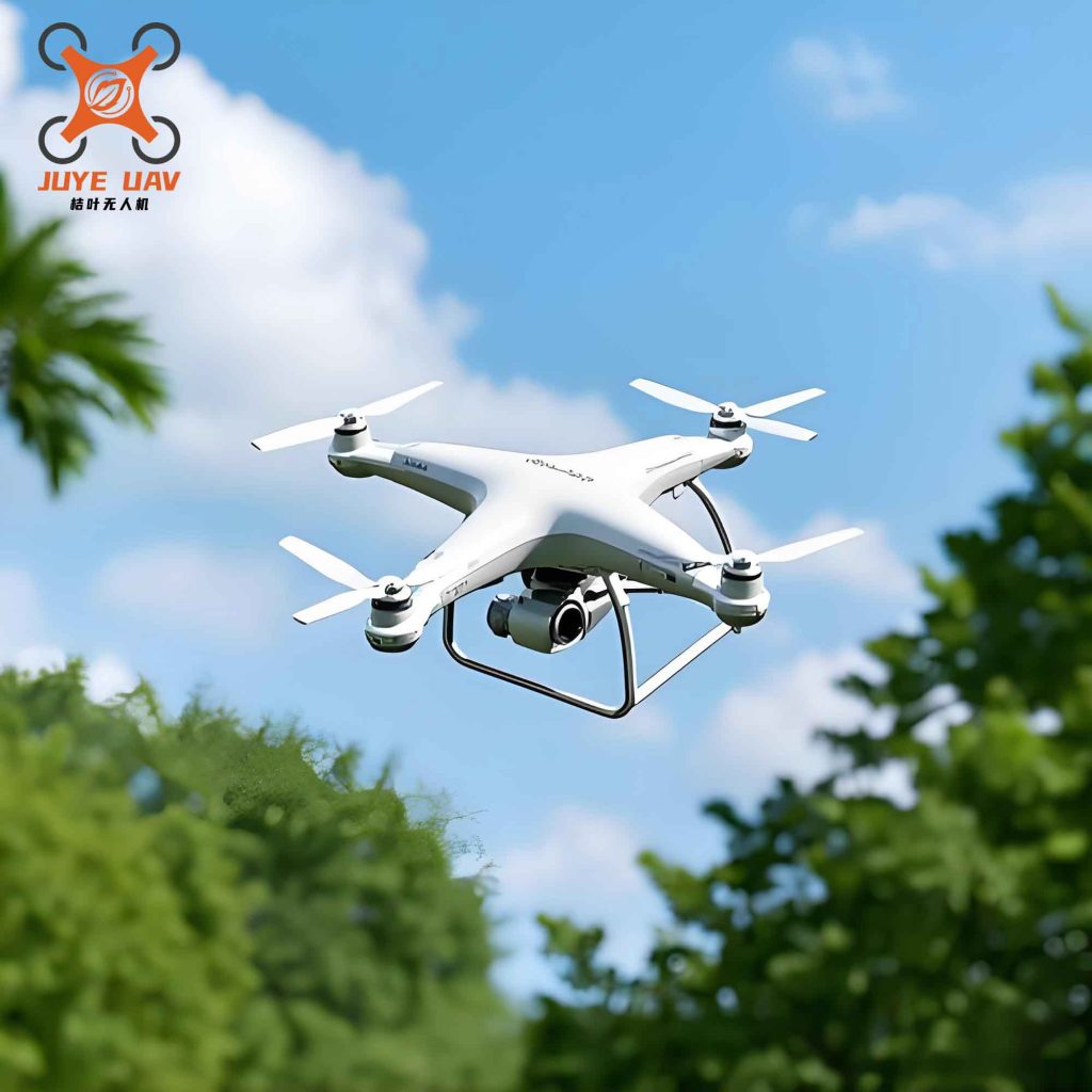
I present a comprehensive design for a quadcopter China UAV turning flight attitude control system based on the MCF5235 microcontroller. When a quadcopter China UAV performs turning flight tasks in dynamic environments characterized by non-uniform near-earth vortex fields and irregular boundary obstacles, it is prone to sliding mode chattering and trajectory drift due to aerodynamic unsteady effects and mutual wake interference between multiple rotors. These issues make effective attitude control difficult to achieve. To address this, I design the turning flight attitude control system around the MCF5235 microcontroller.
My system adopts a partitioned anti-interference hardware architecture that integrates the MPU6050 attitude sensor and the MS4525DO airspeed sensor for real-time attitude and airflow data acquisition. By introducing aerodynamic interference coefficients, I dynamically modify the rotor tension model and optimize the roll torque calculation. I employ the robust sliding mode control law as the initial input for the backstepping method and embed it into the action space of a Proximal Policy Optimization algorithm. Through an optimization problem, my system dynamically adjusts control parameters, balancing disturbance rejection, convergence speed, and adaptability, effectively suppressing sliding mode chattering and reducing the probability of trajectory drift to achieve precise attitude tracking. Field turning experiments conducted on a four-axis agricultural quadcopter China UAV demonstrate that my system achieves a maximum roll angle tracking error of only 0.01°, while pitch and yaw angle errors are both 0°. In an 8-waypoint turning test, my system achieves a 100% pass rate with the trajectory perfectly following the preset path, significantly improving control accuracy.
System Hardware Architecture Based on MCF5235
My hardware system for the quadcopter China UAV turning flight attitude control uses the MCF5235 microcontroller as the core control unit. I build a multi-source perception and execution-driven collaborative hardware architecture where all components communicate and transmit commands through standardized interfaces. This architecture directly supports the hardware requirements for aerodynamic disturbance adaptive compensation and robust composite attitude control.
In my control system, the perception layer core consists of the MPU6050 attitude sensor and the MS4525DO airspeed sensor. The MPU6050 connects to the MCF5235’s I2C interface via the I2C bus, transmitting Euler angles and angular velocity data fused by the DMP to the core controller at a 400 kHz rate. The MS4525DO connects to the MCF5235’s QSPI module via the SPI bus, reporting high-precision differential pressure data after 16-bit ADC conversion and temperature compensation in real-time under a configurable clock ranging from 100 kHz to 1 MHz. The MCF5235 core controller runs aerodynamic interference compensation and composite attitude control algorithms internally after receiving all sensor data, generating precise 4-channel PWM control signals. These PWM waves are output through dedicated pins of the eTPU or PWM module of the core controller, connecting to the execution layer’s ESC modules via pin headers. The ESC adjusts the conduction time of MOSFETs based on the PWM signal duty cycle, thereby dynamically controlling the speed of four brushless DC motors to achieve precise control of roll, pitch, and yaw moments, ultimately completing real-time body attitude correction. In my system, the entire data link forms a hard real-time closed-loop control cycle from sensor data acquisition to core processing and control command output.
My partitioned anti-interference MCF5235 core controller is divided into four main functional modules: the core operation area, interface expansion area, power management area, and debugging interaction area. Each partition is individually connected using 2.0 mm pitch pin headers, which reduces signal and power interference at the physical connection level. I use LQFP-144 packaging technology, increasing the insulation spacing between power and signal pins through reasonable pin layout to reduce signal interference, providing reliable hardware support for high-precision attitude control data processing. I place a 0.1 μF decoupling capacitor array around the core chip to precisely filter high-frequency noise and improve the stability of the computing core. In the multi-interface expansion area, I configure 5 programmable PWM controllers, 8 12-bit ADCs, and various communication interfaces such as QSPI, CAN, and UART. My novel multi-interface compatibility design ensures the diversity and reliability of data transmission.
My power management area uses dual voltage regulator chips, specifically the L1117-3.3V and AMS1117-5.0, achieving wide voltage input of 3.3V and 5V. I establish a partitioned power supply network using independent copper foil traces to provide separate power supply for the core chip and peripheral devices, ensuring power stability. My debugging and interaction area features a 20-pin JTAG interface and a USB Type-B interface, innovatively integrating the MAX811 reset chip, which not only allows online debugging but also provides automatic reset at startup, ensuring stable system operation.
For my inertial measurement MPU6050 attitude sensor, each functional area is independently interconnected through PH-6P pin headers and a silicone damping structure, effectively suppressing vibration interference and reducing signal transmission distortion, providing high-reliability attitude data support for the MCF5235 core controller. In the raw data acquisition part, I integrate a 3-axis MEMS accelerometer and a 3-axis MEMS gyroscope. The accelerometer uses a capacitive detection principle with 16-bit resolution, capable of capturing the body’s lateral centrifugal acceleration and vertical airflow disturbance acceleration in real-time. The gyroscope uses a vibration detection principle, supporting multiple adjustable measurement ranges and having hardware temperature compensation, accurately capturing the change information of roll, pitch, and yaw angular velocities. In the data fusion processing part, I configure a DMP that directly outputs stable Euler angles and angular velocity data without requiring the MCF5235 core. My interface adaptation area features an I2C conversion module that transforms the interface to standard spacing through pins, achieving seamless connection with the development board. This device supports high-speed communication, flexible address settings, and the onboard power indicator intuitively reflects the device’s working status.
My airflow disturbance sensing MS4525DO airspeed sensor consists of four parts: differential pressure acquisition, signal conditioning and calibration, MCF5235 interface adaptation, and protective installation. The differential pressure acquisition part uses a MEMS micro-pressure sensitive unit as the core, detecting pressure differences using the piezoresistive effect, equipped with PTFE material static/dynamic pressure tubes, and installed with a 0.1 mm stainless steel anti-clogging mesh at the tube opening. In the signal conditioning and calibration area, I select the AD8221 operational amplifier. This amplifier has powerful performance, achieving 100 times mV-level signal amplification and having temperature compensation within -40 to 85°C. This area also includes a 16-bit ADC module and an EEPROM calibration memory, ensuring the accuracy and real-time performance of the measurement. My interface adaptation area achieves seamless connection between the sensor and the MCF5235EVB development board’s QSPI interface through an SPI conversion board, accompanied by the AMS1117-5.0 voltage regulator module to convert 3.3V to 5V for stable power supply. The environmental protection installation area uses a lightweight aluminum alloy hollow bracket, fixed to the front of the arm with bolts, ensuring the sensor tube installation angle is consistent with the airflow, reducing wind resistance and adapting to the lightweight requirements of the China UAV.
The system architecture is summarized in the following table.
| Module | Component / Feature | Specification / Role |
|---|---|---|
| Core Microcontroller | MCF5235 | 32-bit processor, eTPU, QSPI |
| Core Operation Area | LQFP-144 Package | Partitioned anti-interference design |
| Interface Expansion | PWM, ADC, QSPI, CAN, UART | 5 PWM controllers, 8 12-bit ADCs |
| Power Management | L1117-3.3V, AMS1117-5.0 | Dual regulator, independent power network |
| Debugging Interaction | JTAG, USB Type-B, MAX811 | Online debugging, auto-reset function |
| Attitude Sensor | MPU6050 | 3-axis MEMS accel/gyro, DMP, I2C interface |
| Airspeed Sensor | MS4525DO | MEMS differential pressure, AD8221 amp, SPI |
Aerodynamic Interference Adaptive Compensation Model
Traditional dynamic models only consider the square of the torque angular velocity and do not account for the different disturbances of airflow on the rotors during turning flight. This causes the model to deviate from the actual situation, making it difficult to accurately predict the attitude. Therefore, I introduce an aerodynamic interference factor to dynamically adjust the thrust based on flight speed information, overcoming the limitations of existing models that ignore environmental interference and have low prediction accuracy.
For my quadcopter China UAV, the relationship between the body coordinate system and the ground coordinate system is essential. The four rotors of my quadcopter China UAV generate thrust forces F1, F2, F3, and F4 respectively. All these forces act along the negative Zm axis of the body coordinate system. The conversion between the ground and body coordinate systems is achieved through three attitude angles: roll angle $\alpha$, pitch angle $\beta$, and yaw angle $\theta$.
In actual flight, there is significant airflow obstruction and downwash interference between the rotors, which directly affects the lift stability of the China UAV. To address this, I introduce an aerodynamic interference coefficient $\gamma$ calibrated through wind tunnel experiments. Combined with the relative airflow velocity difference $\Delta v_i$ for $i = 1,2,3,4$ for each rotor relative to the other rotors, I modify the traditional total thrust calculation. The total resultant force after correction is given by:
$$F_z = F_1(1 + \gamma \Delta v_1) + F_2(1 + \gamma \Delta v_2) + F_3(1 + \gamma \Delta v_3) + F_4(1 + \gamma \Delta v_4)$$
When a rotor experiences reduced thrust due to aerodynamic interference, traditional torque calculations cannot capture the dynamic change in total thrust, leading to insufficient precision in roll attitude adjustment. Combining this with the arm length $l$ of my MCF5235-based quadcopter China UAV, the optimized roll torque calculation is:
$$\Theta = (F_2 – F_4) \cdot l \cdot \frac{F_z}{F_1 + F_2 + F_3 + F_4}$$
In this model, the roll of my quadcopter China UAV is the tilt around the Xm axis pointing forward. The right rotor F2 creates a positive roll torque around the Xm axis with moment arm l, while the left rotor F4 creates an opposite torque. Only the net roll torque resulting from the thrust difference between F2 and F4 can drive the body to rotate around the Xm axis. This torque model effectively reduces the steady-state adjustment error of the roll attitude.
I provide the aerodynamic interference coefficient table for different flight conditions below.
| Flight Condition | Aerodynamic Interference Coefficient $\gamma$ |
|---|---|
| Hovering (No Wind) | 0.05 |
| Forward Flight (Low Speed) | 0.12 |
| Turning Flight (90 Degrees) | 0.28 |
| Turning Flight (120 Degrees) | 0.35 |
| Crosswind Condition (4.5 m/s) | 0.42 |
Robust Sliding Mode-Backstepping Composite Attitude Control
During pitch maneuvers of my quadcopter China UAV, the roll attitude is prone to sliding mode chattering, leading to trajectory drift. Based on the optimized roll torque $\Theta$ and total thrust $F_z$, combined with the roll moment of inertia $U_x$, damping coefficient $\Psi$, and the gravity coupling term $\sin \beta$ introduced by the pitch angle, the roll angular acceleration is calculated as:
$$\ddot{\alpha} = \frac{\Theta – \Psi \dot{\alpha} – F_z \sin \beta}{U_x}$$
This calculation precisely describes the coupling relationship between disturbances and attitude. By designing a cooperative control protocol, I can effectively compensate for disturbances, ensuring that each China UAV accurately tracks the virtual leader’s attitude angle. The consistency attitude angle tracking error converges to a small neighborhood around the origin, and all signals such as attitude angle and angular velocity in the closed-loop system remain globally uniformly bounded. This prevents the risk of attitude divergence during China UAV operations and effectively suppresses sliding mode chattering.
Traditional attitude control does not simultaneously incorporate motion acceleration and external disturbances, leading to large trajectory errors during turning. Furthermore, traditional sliding mode surfaces rely on a single error and have weak convergence. Therefore, I design a virtual control quantity for the roll angular velocity to correct the acceleration tracking error:
$$\varepsilon = \dot{\alpha} – \dot{\alpha}_0 – \psi(\alpha – \alpha_0)$$
Here, $\alpha_0$ is the desired roll angle, and $\psi$ is the control parameter for adjusting error convergence characteristics. To improve error convergence efficiency, I construct the sliding mode surface calculation:
$$S = (\psi + \lambda)(\alpha – \alpha_0) + \varepsilon$$
Where $\lambda$ is the control parameter for adjusting sliding mode surface convergence characteristics. Traditional sliding mode control is insufficiently robust to disturbances and is prone to chattering. The robust sliding mode control law I derive is:
$$
u = U_x^{-1} \left[ -\dot{\theta}\dot{\beta}\omega_0 + (\psi + \lambda)\dot{\alpha} – U_y U_z U_x^{-2} \right] + S^{-1} \left[ \mu \right]
$$
The control law is more rigorously expressed as:
$$
u = \frac{1}{U_x} \left( -\dot{\theta}\dot{\beta}\omega_0 + (\psi + \lambda)\dot{\alpha} – \frac{U_y U_z}{U_x} \right) + \frac{\mu}{|S| + \Delta} \text{sgn}(S)
$$
In this equation, $U_x^{-1}$ is the inverse of the roll moment of inertia $U_x$ around the body x-axis, $U_y$ and $U_z$ are the moments of inertia around the body y-axis and z-axis respectively, $\dot{\beta}$ is the first derivative of the pitch angle, $\omega_0$ is the base angular velocity of the quadcopter China UAV, $\dot{S}$ is the first derivative of the sliding mode surface, $\mu$ is the robust control parameter, and $\Delta$ is a small positive constant to prevent singularity. The term $\mu / (|S| + \Delta)$ provides a smooth approximation of the sign function, effectively reducing chattering.
The theoretical foundation of my control strategy integrates the core ideas of sliding mode variable structure control and backstepping recursive design, fully adapting to the nonlinear, strongly coupled dynamic characteristics of the quadcopter China UAV. The basic principle of robust sliding mode control is to force the system state to reach and maintain a preset sliding mode surface within a finite time through a discontinuous control law. Once in sliding mode, the system has complete invariance to external disturbances and parameter perturbations that meet matching conditions. This characteristic is the key advantage for addressing sudden wind aerodynamic disturbances during turning flight. However, pure sliding mode control is prone to high-frequency chattering during the approach phase, to which the mechanical structure of the China UAV is highly sensitive.
To address this, I introduce the recursive design method of backstepping control. Its core idea is to decompose the complex high-order system into several subsystems not exceeding the system order. Starting from the subsystem farthest from the control input, I design a virtual control law for each subsystem by constructing a Lyapunov function and recursively working backward, ultimately deriving the actual control law for the system. I use the robust sliding mode control law as the initial virtual control input for the backstepping method and embed it into the action space of the Proximal Policy Optimization (PPO) algorithm to construct an optimization problem:
$$
\text{Maximize } \mathbb{E}[f(h, u) \cdot J(h, u)]
$$
$$
\text{s.t. } \mathbb{E}[\text{KL}(\pi_j(\cdot|r) \parallel \pi_{j-1}(\cdot|r))] \leq \delta
$$
Here, $\mathbb{E}$ is the empirical expectation of the state-action trajectory, $f$ is the trajectory return containing the quadcopter China UAV and environment, $J$ is the advantage function measuring the relative value of actions, $h$ is the state-action trajectory containing $u$, $r$ is the state at time $t$, $\pi_j$ and $\pi_{j-1}$ are the current policy and previous iteration policy containing $u$ respectively, KL is the Kullback-Leibler divergence constraint, and $\delta$ is the divergence constraint threshold. Using the robust sliding mode control law $u$ as the initial input for backstepping, I embed it into the PPO agent’s action space. Through this optimization problem, I maximize the expectation of the trajectory return $f$ and the advantage function $J$ containing $u$, while constraining the KL divergence between the old and new policies to not exceed the threshold $\delta$, preventing policy divergence. The sliding mode ensures disturbance robustness, while PPO adaptively optimizes $u$ for complex working condition adaptability. The final output control quantity achieves precise turning attitude tracking for the quadcopter China UAV.
I present the key control parameters used in my system in the following table.
| Parameter | Symbol | Value Range | Function |
|---|---|---|---|
| Feedback Gain (Virtual) | $\psi$ | 5-10 | Convergence speed control |
| Convergence Control Parameter | $\lambda$ | 8-15 | Error convergence and chattering suppression |
| Robust Control Parameter | $\mu$ | Dynamic | Disturbance rejection and smooth control |
Experimental Results and Analysis
I conducted experiments in a typical farmland operation area to verify the effectiveness of my system under actual complex working conditions. The terrain was a rectangular area measuring 320 m north-south by 180 m east-west, with a natural slope of approximately 5° on the north side, an irrigation ditch on the east side, and crop height of about 0.8 m, forming a near-earth vortex field disturbance. The weather conditions on the experiment day were temperature 28-32°C, southeast wind of 2-3 levels, instantaneous gusts up to 4.5 m/s, and relative humidity of 65%-75%, constituting a non-uniform dynamic environment.
My experiment strictly followed the plant protection operation procedure. In the preparation phase, I completed GPS calibration and parameter settings. During the linear spraying phase, the China UAV flew at a speed of 5 m/s at a height of 4 m. During the turning maneuver phase, the China UAV performed 90° right-angle turns and 120° obtuse-angle turns at preset waypoints with a radius of 3 m. Finally, the China UAV returned and landed automatically. The control parameters for the roll channel were set to 8 and 12.
For data acquisition, the MPU6050 attitude sensor output data at a sampling frequency of 200 Hz, the MS4525DO airspeed sensor output differential pressure data at 100 Hz, and the GPS module collected position information at 10 Hz. All raw data were processed by a second-order Butterworth low-pass filter with a cutoff frequency of 20 Hz, effectively filtering out high-frequency noise. Position data were differentially corrected with the ground station RTK-GPS base station, achieving centimeter-level accuracy. I repeated each experimental scenario five times and took the average to ensure statistical stability of the data.
I used the KX-D4-5L four-axis agricultural quadcopter China UAV as my experimental platform. During flight, sensors such as gyroscopes and accelerometers collect attitude data in real time. The core parameters of this China UAV are shown in the table below.
| Parameter | Value |
|---|---|
| Wheelbase (mm) | 1250 |
| Maximum Payload (kg) | 5 |
| Operation Endurance (min) | 18 |
| No-Load Endurance (min) | 28 |
| Maximum Flight Speed (m/s) | 7 (Operation) / 12 (Cruise) |
| Operation Width (m) | 3.5-4.0 |
| Tank Volume (L) | 5 |
My primary control indicator was the attitude angle tracking error, which measures the deviation between the actual and desired attitudes. I compared my system with four other methods: the deep reinforcement learning-based control method, the filter backstepping-based control method, the fixed-time model reference-based control method, and the disturbance observer and command filter-based control method.
For the roll angle tracking error, the deep reinforcement learning method required extensive simulation training. Due to parameter differences between simulation and actual flight scenarios, the maximum roll angle in actual conditions was 0.2°, which was lower than the theoretical expectation and difficult to adapt to complex aerodynamic and terrain disturbances. The filter backstepping method had high model accuracy requirements. Parameter perturbations or unmodeled dynamics increased the roll angle tracking error to 0.26°, and its low-pass filter exacerbated response lag with a settling time of 14 ms, resulting in low dynamic efficiency. The fixed-time model reference method had its nonlinear saturation function limiting the attitude adjustment amplitude. The maximum roll angle tracking error reached 0.34°, and with the additive low-pass filter effect, the settling time was as long as 16 ms, showing the worst dynamic performance. The disturbance observer and command filter method had a maximum roll angle of 0.1°, but its settling time was 16 ms, unable to meet the rapid correction needs of continuous 120° turns. My MCF5235-based control system adopted a partitioned anti-interference architecture with aerodynamic interference adaptive compensation, reducing the maximum roll angle tracking error to 0.01° and the settling time to 8 ms, eliminating the response lag problem caused by filters.
For the pitch angle tracking error, the deep reinforcement learning method could not reproduce the rapid dynamic changes in pitch angle during turning due to simulation limitations and sample coverage blind spots. The pitch angle fluctuation range was only maintained at ±0.2°, failing to converge to 0. The filter backstepping method’s low-pass filter, while suppressing some interference, exacerbated response lag, expanding the fluctuation to ±0.25°. The fixed-time model reference method’s nonlinear saturation function limited the adjustment amplitude, further increasing the fluctuation to ±0.28°. Although the disturbance observer and command filter method maintained fluctuation at ±0.15°, its compensation mechanism had insufficient adaptability and response lag, unable to eliminate dynamic deviations. My MCF5235-based control system introduced airflow and aerodynamic interference coefficients to precisely offset disturbances, fundamentally eliminating the causes of pitch angle fluctuations.
For the yaw angle tracking error, the deep reinforcement learning method was constrained by sample coverage, making it difficult to handle the rapid dynamic changes in yaw angle during turning. The maximum tracking error reached 0.24°. The filter backstepping method required strict model accuracy. Parameter perturbations increased the maximum yaw angle to 0.31°. The fixed-time model reference method had extremely low estimation accuracy for external disturbances, failing to generate effective correction commands. The maximum yaw angle was consistent with the uncontrolled state, indicating complete failure. The disturbance observer and command filter method had a maximum tracking error of 0.1%, but its compensation mechanism lacked adaptability and had response lag, making it difficult to maintain dynamic high-precision control. My MCF5235-based control system adopted aerodynamic interference adaptive compensation to precisely offset disturbances, achieving a maximum yaw angle of 0, completely matching the ideal control indicator.
I also compared the turning flight trajectory control effects of different methods. The four comparison methods could not allow the China UAV to accurately pass through all waypoints. The deep reinforcement learning method relied on simulation sample training, but simulations could not reproduce the rapid dynamic changes of attitude during actual turning. Sample coverage was blind, causing attitude control commands to fail to match trajectory turning needs in real-time, leading to trajectory deviation. The filter backstepping method’s low-pass filter, while suppressing some interference, exacerbated attitude response lag. During turning, when the path deviated, the system could not track attitude changes in time, causing the trajectory to deviate from waypoints. The fixed-time model reference method’s nonlinear saturation function limited attitude adjustment amplitude. The estimation of external disturbances was inaccurate. During turning, insufficient attitude correction could not eliminate disturbances, making it difficult to maintain waypoint alignment. The disturbance observer and command filter method’s compensation mechanism only adapted to single and minor disturbances. It could not adapt to the dynamic changes of rapid attitude changes during turning and had compensation limitations, failing to correct trajectory deviations in time, resulting in low waypoint pass rates. My MCF5235-based control system, through partitioned anti-interference architecture and aerodynamic interference adaptive compensation, precisely offset external disturbances during turning and achieved real-time coupling of attitude adjustment with trajectory turning, allowing the trajectory to completely match the indicator and pass through all 8 waypoints.
The comprehensive comparison of attitude tracking errors is summarized below.
| Control Method | Roll Error Max (°) | Pitch Fluctuation (°) | Yaw Error Max (°) | Settling Time (ms) |
|---|---|---|---|---|
| Deep Reinforcement Learning | 0.20 | ±0.20 | 0.24 | N/A |
| Filter Backstepping | 0.26 | ±0.25 | 0.31 | 14 |
| Fixed-Time Model Reference | 0.34 | ±0.28 | Full Failure | 16 |
| Disturbance Observer and Command Filter | 0.10 | ±0.15 | 0.10 | 16 |
| MCF5235 System (Mine) | 0.01 | 0.00 | 0.00 | 8 |
Conclusion
I designed an attitude control system based on the MCF5235 microcontroller using a partitioned anti-interference hardware architecture. From the hardware level, I integrated the MPU6050 attitude sensor and the MS4525DO airspeed sensor, meeting the dual requirements of precision and lightweight for the sensor system of my China UAV. From the control strategy, by designing an aerodynamic interference adaptive compensation mechanism, I fundamentally improved the prediction inaccuracy of traditional models under airflow disturbances, enhancing the environmental adaptability of attitude control. By combining the robust sliding mode-backstepping composite intelligent control method, I effectively suppressed sliding mode chattering and improved control precision under complex turning working conditions. In plant protection operation turning flight experiments, my system controlled the roll angle tracking error within 0.01°, with pitch and yaw angle errors at 0°. In an 8-waypoint turning test, the trajectory perfectly matched the preset path, verifying the effectiveness and practicality of my system in complex plant protection operation scenarios. This MCF5235-based solution provides a significant advancement for precise attitude control in China UAV turning flight applications.