The development of aircraft capable of Vertical Take-Off and Landing (VTOL) while retaining the high-speed cruise efficiency of fixed-wing platforms represents a significant frontier in aerospace engineering. The VTOL UAV concept combines the operational flexibility of rotorcraft with the endurance and speed advantages of conventional aircraft. This paper presents a comprehensive analysis of the longitudinal dynamics and proposes a control strategy for the critical transition phase of a novel VTOL UAV configuration. The design in focus utilizes a three-ducted fan propulsion system integrated into a flying-wing airframe, a configuration chosen for its compact structure and generous internal volume. The primary aerodynamic interactions, stability characteristics, and a safe transition methodology are investigated in detail.
The fundamental challenge for any VTOL UAV lies in the transition corridor between hover and forward flight. This phase is characterized by complex, non-linear aerodynamic interactions, significant changes in trim requirements, and inherent control authority limitations. For the three-ducted fan VTOL UAV, these challenges are accentuated. The ducted fans, while providing efficient vertical lift, introduce substantial induced aerodynamic forces on the wing and body that vary dramatically with airspeed and fan thrust. A failure to properly account for these effects can lead to a loss of control or entry into a “failure cliff” – a dangerous state from which recovery is impossible given the available control power and flight envelope. Therefore, a deep understanding of the coupled dynamics is paramount for developing a viable and safe VTOL UAV.
1. Configuration and Aerodynamic Interference Modeling
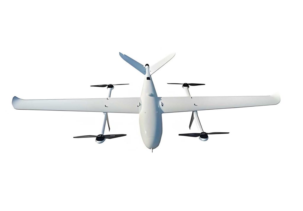
The subject VTOL UAV employs a pure flying-wing layout. Vertical lift is generated by three ducted fans: one mounted on the forward fuselage and two primary units embedded within the inboard sections of the wing. Forward thrust is provided by a separate, conventional turbojet or turbofan engine located at the rear. This distributed propulsion scheme for the VTOL UAV offers inherent redundancy and simplifies control allocation during hover and low-speed flight. However, the integration of large ducted fans into the lifting surface creates a complex flow field. During transition, the fans are active while the aircraft gains forward speed, leading to interference effects that cannot be captured by simple superposition of isolated component aerodynamics.
The total aerodynamic forces and moments acting on the VTOL UAV during transition are modeled as the sum of the clean-airframe aerodynamics and the incremental effects induced by each operating ducted fan. For a force or moment component \( A \) (representing lift \(L\), drag \(D\), or pitching moment \(M\)):
$$
A = A_{\text{clean}} + \sum_{i=1}^{3} T_i \cdot \left( \frac{\Delta A}{T} \right)_i
$$
Here, \( A_{\text{clean}} \) is the force/moment of the airframe with inactive, faired-over ducts. \( T_i \) is the thrust of the i-th ducted fan (front, left main, right main), and \( \left( \frac{\Delta A}{T} \right)_i \) is the non-dimensional induced aerodynamic coefficient per unit thrust for that fan. The key to accurate simulation of this VTOL UAV’s behavior is the accurate estimation of these induced terms, which are functions of flight speed, fan thrust (or exit velocity), and aircraft attitude.
The induced effects arise from two primary phenomena: the blockage of freestream flow at the fan inlet and the entrainment and downwash of the high-velocity jet exiting the fan. These effects result in a loss of lift over the wing, an increase in drag, and a significant nose-up pitching moment. Empirical and semi-empirical methods, validated for similar configurations, are used to estimate these increments. The induced lift loss, for instance, is decomposed into a “static” or hover-induced component and a “translational” component:
$$
\frac{\Delta L}{T} = \left( \frac{\Delta L_{\infty}}{T} \right) + \left( \frac{\Delta L_{t}}{T} \right)
$$
The static term correlates with the fan’s geometry and pressure ratio, while the translational term depends strongly on the ratio of freestream dynamic pressure to fan jet dynamic pressure, denoted as the effective velocity ratio \( V_e = \sqrt{q_{\infty} / q_j} \). Similar relations define induced drag and pitching moment. For the primary ducted fans of this VTOL UAV, the induced aerodynamic increments at zero angle-of-attack and out-of-ground-effect are calculated as functions of forward speed \(V\) and fan rotational speed \(n\), which is a proxy for thrust. The following table summarizes the key parameters for the primary ducted fans used in the analysis:
| Parameter | Symbol | Value |
|---|---|---|
| Fan Exit Diameter | \(D_e\) | 1.909 m |
| Exit Area | \(A_j\) | 2.863 m² |
| Wing Reference Area | \(S\) | 30.0 m² |
| Area Ratio Parameter | \(K_1 = \sqrt{S/A_j}\) | 0.916 |
| Longitudinal Arm (fan exit to CG) | \(X_j\) | 0.309 m |
The calculated trends for one primary ducted fan are highly non-linear. At a constant high fan speed, the induced lift loss and drag increase nearly linearly with airspeed. However, if the fan speed is reduced while maintaining a constant airspeed, these induced forces drop precipitously. This non-linearity is central to the transition control problem. The induced nose-up pitching moment is particularly significant as it directly opposes the natural pitch-down moment generated by the forward thrust component acting below the center of gravity, creating a challenging trim scenario for the VTOL UAV.
2. A Proposed Transition Flight Control Strategy
Designing a safe transition profile for the VTOL UAV requires managing multiple constraints simultaneously: available thrust, control surface authority, actuator rate limits, and the avoidance of the aforementioned failure cliffs. The strategy must smoothly transfer the load from purely thrust-borne to aerodynamically-borne lift while maintaining controllable flight.
The proposed strategy is a “pre-set angle of attack” acceleration profile, followed by a sequential shutdown of the lift fans. The logic is as follows:
- Helicopter Mode to Initial Acceleration: From a stable hover, the aircraft is pitched to a pre-selected, fixed angle of attack (e.g., 7°). This is the angle that provides adequate lift at the target minimum safe airspeed for fixed-wing flight (e.g., 55 m/s). Forward thrust is gradually applied from the rear engine.
- Constant-Attitude Acceleration: The VTOL UAV accelerates while holding the preset angle of attack. The ducted fans maintain sufficient thrust to compensate for the aircraft’s weight, minus the small but growing aerodynamic lift, and plus the now-substantial induced lift loss. The flight control system continuously adjusts fan speeds and control surface deflections (elevons) to maintain pitch attitude and heave rate.
- Primary Fan Shutdown: Upon reaching the minimum safe airspeed, where aerodynamic lift can fully support the weight, the two main ducted fans (which contribute most to the adverse induced moments) are progressively shut down. Their thrust is ramped to zero over a few seconds.
- Forward Fan Shutdown & Clean Configuration: After the main fans are secured, the front ducted fan is shut down. The aircraft is now in a conventional, clean fixed-wing configuration, operating solely on its rear engine and aerodynamic surfaces.
This strategy provides inherent safety margins. By presetting the angle of attack to the value needed for level flight at the target speed, the aircraft naturally transitions to a sustainable aerodynamic state. The sequential shutdown prioritizes the removal of the most destabilizing elements (the main fans) first, while retaining the forward fan for pitch control until the final phase. The critical parameters throughout this maneuver for a sample VTOL UAV weighing 2400 kg are summarized below:
| Flight Phase | Airspeed (m/s) | Angle of Attack (deg) | Total Ducted Fan Thrust (N) | Rear Engine Thrust (N) | Eleven Deflection (deg) |
|---|---|---|---|---|---|
| Hover | 0 | 0 | ~23,500 | 0 | -8 |
| Mid-Transition | 30 | 7 | ~18,000 | ~5,000 | -5 |
| Safe Speed Attained | 55 | 7 | ~12,000 | ~4,000 | 2 |
| After Main Fan Shutdown | 55 | 7 | ~3,000 (front only) | ~4,000 | 8 |
| Fixed-Wing Flight | >55 | Variable | 0 | ~3,000 | Variable |
The table reveals key insights: the total required thrust peaks around 30 m/s due to high drag and significant induced lift loss. The eleven deflection trends from negative to positive, reflecting the battle between the nose-up induced moment and the nose-down moment from the rear thrust. Importantly, all parameters remain within operational limits, validating that this strategy keeps the VTOL UAV away from failure cliffs.
3. Longitudinal Stability Analysis During Transition
The longitudinal dynamics of the VTOL UAV during transition are analyzed using the linearized small-perturbation equations of motion. The state vector is \(\mathbf{x} = [u, w, q, \theta]^T\), representing perturbations in forward speed, vertical speed, pitch rate, and pitch attitude. The system matrix \(\mathbf{A}\) is derived from the aircraft’s stability and control derivatives. The unique aspect for this VTOL UAV is the profound influence of the ducted fans on these derivatives.
Each dimensional stability derivative must be modified to include the direct effect of thrust variation with state variables and the variation of the induced aerodynamic forces. For example, the speed damping derivative \(X_u\) (often normalized as \(X_V\)) is heavily affected by the induced drag’s strong dependence on airspeed. Its modified form can be expressed conceptually as:
$$
X_V = X_{V,\text{clean}} + \frac{1}{mV_0} \sum_i \left[ \frac{\partial T_i}{\partial V} \cos(\alpha_0 + \phi_i) + \frac{\partial (\Delta D_i)}{\partial V} \right]
$$
where \(X_{V,\text{clean}}\) is the derivative for the clean airframe, \(m\) is mass, \(V_0\) is the trim speed, and \(\phi_i\) is the tilt angle of the i-th thrust vector. Similar corrections apply to \(Z_V\), \(M_V\), \(Z_\alpha\), \(X_\alpha\), \(M_\alpha\), \(Z_q\), and \(M_q\). The partial derivatives of thrust and induced forces are evaluated numerically from the aerodynamic interference model at the trim condition.
A comparative analysis at a transition speed of 30 m/s clearly shows the impact of the ducted fans on the VTOL UAV’s longitudinal stability characteristics:
| Stability Derivative | Clean Configuration | With Ducted Fans Active | Physical Reason |
|---|---|---|---|
| \(Z_V\) (Speed damping in z-axis) | +0.009 | +0.005 | Induced lift loss increases with speed, reducing the heave damping. |
| \(X_V\) (Speed damping in x-axis) | -0.037 | -0.188 | Induced drag increases sharply with speed, greatly increasing drag damping. |
| \(M_\alpha\) (Pitch stiffness) | -0.690 | -0.290 | Induced nose-up moment increases with AOA, reducing the net restoring moment (destabilizing). |
| \(Z_\alpha\) (Lift curve slope) | +0.709 | +0.573 | Lift generation is less effective due to fan flow interference. |
The most critical observation is the reduction in pitch stiffness (\(|M_\alpha|\) decreases). This directly impacts the short-period mode. Solving the eigenvalue problem for the state matrix reveals the modal characteristics. For the clean configuration at 30 m/s, the classic short-period and phugoid modes are present:
Clean VTOL UAV (Fans Off):
Short-Period: \(\lambda_{sp} = -0.888 \pm 0.826i \quad (\zeta=0.73, \omega_n=1.21 \text{ rad/s})\)
Phugoid: \(\lambda_{ph} = -0.013 \pm 0.002i \quad (\zeta=0.06, \omega_n=0.20 \text{ rad/s})\)
VTOL UAV in Transition (Fans Active):
The eigenvalues shift significantly:
\(\lambda_1 = -1.10, \quad \lambda_2 = -0.519\)
Phugoid: \(\lambda_{ph} = -0.096 \pm 0.523i \quad (\zeta=0.18, \omega_n=0.53 \text{ rad/s})\)
The active ducted fans cause the short-period mode to degenerate from a complex conjugate pair into two real, aperiodic roots (\(\lambda_1, \lambda_2\)). This indicates a suppression of the oscillatory pitch response, replacing it with two distinct exponential decay responses—one fast and one slower. This is a direct consequence of the reduced pitch stiffness and altered damping. The phugoid mode frequency increases, and its damping ratio improves substantially due to the large increase in speed damping (\(X_V\)).
The root locus plot showing the migration of these longitudinal roots as the primary ducted fan speed (and thus \(V_e\)) is varied from idle to maximum at a constant 30 m/s airspeed provides further insight. As fan speed increases (moving from right to left on the locus), the short-period roots converge on the real axis and then separate, confirming the transition to aperiodic motion. The phugoid roots consistently move to higher damping and frequency. This analysis confirms that while the VTOL UAV remains longitudinally stable during transition, the dynamic characteristics are profoundly and non-linearly altered by the ducted fan operation.
4. Conclusion
The successful design and operation of a VTOL UAV based on a fixed-wing flying wing with integrated ducted fans hinge on mastering the complex dynamics of the transition flight phase. This investigation has detailed the significant aerodynamic interference effects generated by the ducted fans, which manifest as substantial lift loss, drag rise, and a destabilizing nose-up pitching moment. These effects are highly non-linear, depending on both forward speed and fan thrust.
A viable and safe transition control strategy for this VTOL UAV has been formulated, centered on accelerating at a pre-set, fixed angle of attack to a safe fixed-wing speed, followed by the sequential shutdown of the main and then forward ducted fans. This approach maintains adequate control authority and safety margins, preventing entry into hazardous failure cliffs.
The longitudinal stability analysis reveals that the active ducted fans fundamentally alter the dynamic modes of the VTOL UAV. The most notable effect is the degradation of the short-period mode, which transitions from an oscillatory to an aperiodic response due to a reduction in pitch stiffness caused by the induced moments. Conversely, the increased drag damping from the induced effects significantly improves the damping of the phugoid mode. These findings underscore the necessity of a flight control system for the VTOL UAV that is explicitly designed to handle these variable dynamics across the entire flight envelope, from hover through transition to high-speed cruise. The insights and methodology presented here provide a foundational framework for the stability analysis and control law synthesis for this advanced class of VTOL UAV.