
In recent years, the application of drone formations has expanded significantly in both civilian and military domains, including ground reconnaissance, disaster relief, and agricultural surveying. The coordination of multiple drones, or drone formation, offers enhanced reliability and capability to meet complex operational demands. However, traditional formation control methods, such as leader-follower approaches, behavior-based methods, and virtual structure techniques, often face challenges in flexibility and real-time obstacle avoidance. Specifically, the virtual structure method, while maintaining a stable formation, struggles with dynamic transformations and timely responses to unforeseen obstacles. To address these issues, I propose an improved artificial potential field (IAPF) method integrated with a virtual control network for drone formation path planning. This approach enhances the adaptability of drone formation in unknown environments while ensuring smooth and efficient navigation.
The core of my method lies in combining global path planning with local obstacle avoidance. For global planning, a virtual leader guides the drone formation in a diamond-shaped configuration, ensuring cohesive movement. Each drone in the formation occupies a fixed position relative to the virtual leader, creating a structured and stable drone formation. In local planning, I employ an improved artificial potential field (APF) to handle both known and unknown static obstacles. By introducing additional attractive forces from anchor points and target points, the IAPF mitigates common issues like local minima and oscillations, allowing the drone formation to navigate around obstacles and return to its original path. This dual-layer strategy ensures that the drone formation remains robust in complex scenarios.
To formalize the drone formation control model, I start by defining the virtual leader’s role. The virtual leader acts as the geometric center of the formation, and its path is optimized to minimize travel distance and threat exposure. The cost function for the virtual leader’s path planning incorporates both path length and threat cost, weighted accordingly. Let $(x_0, y_0, z_0)$ denote the start coordinates, $(x_n, y_n, z_n)$ the end coordinates, and $(x_i, y_i, z_i)$ for $i = 1, 2, \dots, n-1$ the intermediate waypoints. The path length cost $D$ is given by:
$$D = \sum_{i=1}^{n} \sqrt{(x_i – x_{i-1})^2 + (y_i – y_{i-1})^2 + (z_i – z_{i-1})^2}$$
The threat cost $T$ accounts for proximity to obstacles, with $(x_{ob,j}, y_{ob,j})$ representing the center of obstacle $j$, $d_{ob}$ its influence radius, and $d$ the distance between a waypoint and the obstacle:
$$T = \sum_{j=1}^{m} \sum_{i=1}^{n} \sqrt{(x_i – x_{ob,j})^2 + (y_i – y_{ob,j})^2} \quad \text{for} \quad d < d_{ob}$$
The overall fitness function combines these costs with weights $\omega_1$ and $\omega_2$, where $\omega_1 + \omega_2 = 1$:
$$\text{Fitness} = \omega_1 \cdot D + \omega_2 \cdot T$$
This optimization is performed using a particle swarm optimization (PSO) algorithm to generate an efficient global path for the virtual leader, which in turn guides the entire drone formation.
For the drone formation itself, I establish a virtual control network based on the virtual leader. The formation is structured as a diamond shape, with diagonal lengths $a$ and $b$. The virtual leader’s coordinate vector is $\mathbf{C} = (x, y, z)$, and the direction vectors from the center are defined as:
$$\begin{aligned}
\mathbf{L_1} &= (0, -a, 0) \\
\mathbf{L_2} &= (-b, 0, 0) \\
\mathbf{L_3} &= (0, a, 0) \\
\mathbf{L_4} &= (b, 0, 0)
\end{aligned}$$
The coordinates of the diamond vertices, which serve as virtual control points, are calculated as $\mathbf{P_{z,i}} = \mathbf{C} + \mathbf{L_i}$ for $i = 1, 2, 3, 4$. The midpoints of the diamond edges are derived as:
$$\begin{aligned}
\mathbf{P_{z,5}} &= \frac{1}{2}(\mathbf{P_{z,1}} + \mathbf{P_{z,2}}) \\
\mathbf{P_{z,6}} &= \frac{1}{2}(\mathbf{P_{z,2}} + \mathbf{P_{z,3}}) \\
\mathbf{P_{z,7}} &= \frac{1}{2}(\mathbf{P_{z,3}} + \mathbf{P_{z,4}}) \\
\mathbf{P_{z,8}} &= \frac{1}{2}(\mathbf{P_{z,4}} + \mathbf{P_{z,1}})
\end{aligned}$$
Each drone in the formation is assigned to a virtual control point using the Hungarian algorithm to minimize total movement distance. This ensures an efficient initial setup for the drone formation. The drones then move under the influence of artificial potential fields, which include attractive forces from their assigned virtual control points and repulsive forces from obstacles and other drones. The attractive force $F_{\text{att}}$ and repulsive force $F_{\text{rep}}$ are defined as:
$$F_{\text{att}} = k_{\text{att}} \|\mathbf{P_z} – \mathbf{q}\|$$
$$F_{\text{rep}} =
\begin{cases}
k_{\text{rep}} \left( \frac{1}{\|\mathbf{q_{ob}} – \mathbf{q}\|} – \frac{1}{p_0} \right) \frac{1}{\|\mathbf{q_{ob}} – \mathbf{q}\|^2}, & \|\mathbf{q_{ob}} – \mathbf{q}\| \leq d_{ob} \\
0, & \|\mathbf{q_{ob}} – \mathbf{q}\| > d_{ob}
\end{cases}$$
Here, $k_{\text{att}}$ and $k_{\text{rep}}$ are gain coefficients, $\mathbf{q}$ is the drone’s position, $\mathbf{P_z}$ is the virtual control point, $\mathbf{q_{ob}}$ is the obstacle center, and $d_{ob}$ is the obstacle’s influence range. The resultant force balances these interactions, allowing each drone to maintain its position in the drone formation while avoiding collisions.
In global path planning, the virtual leader’s path is computed considering known obstacles. However, if a virtual control point falls within an obstacle region, it is adjusted outward along the vector from the obstacle center to the control point. The new coordinate $\mathbf{P_{\text{new}}}$ is given by:
$$\mathbf{P_{\text{new}}} = \mathbf{P_z} + \frac{\mathbf{CP_z}}{\|\mathbf{CP_z}\|} (d_{\text{se}} – \|\mathbf{CP_z}\|) \quad \text{for} \quad \|\mathbf{CP_z}\| < d_{\text{se}}$$
where $d_{\text{se}}$ is a safe distance from the obstacle. This adjustment ensures that the drone formation can navigate around known obstacles without compromising the formation structure.
For unknown static obstacles encountered during flight, I introduce an improved APF method. When a drone’s sensors detect an unknown obstacle, point cloud data is clustered using K-means to estimate the obstacle’s centroid $\mathbf{q_{cd}}$. The repulsive potential field $U_{\text{rep}}(\mathbf{q})$ and corresponding force $F_{\text{rep}}$ are defined similarly to the standard APF but with adjustments for dynamic detection:
$$U_{\text{rep}}(\mathbf{q}) =
\begin{cases}
\frac{1}{2} k_{\text{rep}} \left( \frac{1}{\|\mathbf{q_{cd}} – \mathbf{q}\|} – \frac{1}{d_{ob}} \right)^2, & \|\mathbf{q_{cd}} – \mathbf{q}\| \leq d_{ob} \\
0, & \|\mathbf{q_{cd}} – \mathbf{q}\| > d_{ob}
\end{cases}$$
$$F_{\text{rep}} =
\begin{cases}
k_{\text{rep}} \left( \frac{1}{\|\mathbf{q_{cd}} – \mathbf{q}\|} – \frac{1}{d_{ob}} \right) \frac{1}{\|\mathbf{q_{cd}} – \mathbf{q}\|^2}, & \|\mathbf{q_{cd}} – \mathbf{q}\| \leq d_{ob} \\
0, & \|\mathbf{q_{cd}} – \mathbf{q}\| > d_{ob}
\end{cases}$$
To overcome local minima, I establish a new coordinate system based on the drone’s heading direction and the repulsive force vector. Let $\phi$ be the drone’s trajectory angle, $\rho$ the angle of the vector from the drone to the obstacle centroid, and $\theta = \phi – \rho$. A rotation matrix $\mathbf{E}$ is defined as:
$$\mathbf{E} =
\begin{cases}
\begin{bmatrix} 0 & 1 \\ -1 & 0 \end{bmatrix}, & \theta > 0 \\
\begin{bmatrix} 0 & -1 \\ 1 & 0 \end{bmatrix}, & \theta < 0
\end{cases}$$
In this new coordinate system, I select an anchor point from radar detection points by choosing the one with the maximum angle relative to the negative X-axis. The anchor point exerts an attractive force $F_{\text{ap}}$ on the drone, while a target point $\mathbf{q_{tg}}$ placed along the obstacle’s tangent line provides additional guidance. These forces are calculated as:
$$F_{\text{ap}} = k_{\text{ap}} \|\mathbf{q_{\text{ap}}} – \mathbf{q}\|$$
$$F_{\text{tg}} = k_{\text{tg}} \|\mathbf{q_{\text{tg}}} – \mathbf{q}\|$$
where $k_{\text{ap}}$ and $k_{\text{tg}}$ are gain coefficients. The total force on a drone in the formation becomes:
$$\mathbf{F_v} = F_{\text{rep}} + F_{\text{ap}} + F_{\text{tg}}$$
This combined force enables the drone formation to smoothly navigate around unknown obstacles while minimizing deviation from the original path. The integration of anchor and target points effectively addresses the limitations of traditional APF, ensuring robust performance for drone formation in unpredictable environments.
To validate the proposed method, I conducted extensive simulation experiments. The drone formation consisted of eight drones initialized randomly in a three-dimensional plane. The parameters for formation control and IAPF were set as shown in the following tables:
| Parameter | Value |
|---|---|
| Number of Drones | 8 |
| Initial Drone Velocity | 0 m/s |
| Virtual Leader Position | (0, 0, 0) |
| Diagonal Length a | 4 m |
| Diagonal Length b | 8 m |
| Inter-Drone Repulsion Distance | 1 m |
| Inter-Drone Repulsion Coefficient | 0.50 |
| Maximum Drone Speed | 2 m/s |
| Parameter | Value |
|---|---|
| Repulsion Coefficient $k_{\text{rep}}$ | 500 |
| Anchor Point Attraction Coefficient $k_{\text{ap}}$ | 0.20 |
| Target Point Attraction Coefficient $k_{\text{tg}}$ | 0.17 |
| Repulsion Field Influence Range $d_{ob}$ | 15 m |
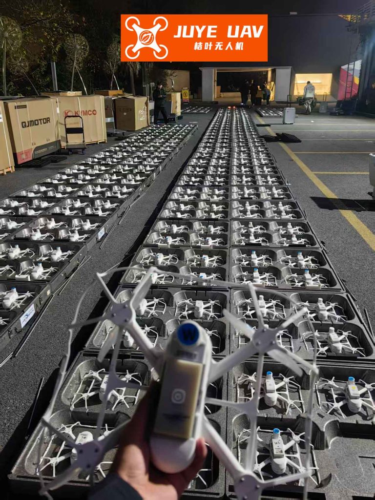
The formation process was simulated over time, with drones gradually moving toward their assigned virtual control points. Within 4.0 seconds, the drones successfully formed a stable diamond-shaped drone formation, demonstrating the efficiency of the virtual control network. The following figure illustrates the cohesive nature of such drone formations, often seen in applications like light shows:
For obstacle avoidance, I tested the IAPF in a 50 m × 40 m environment with an unknown static obstacle centered at (25, 20) and a radius of 10 m. The drone formation started at (0, 20) with a target at (40, 20). The global path was a straight line, but upon detecting the obstacle at (5, 20), the formation utilized IAPF to navigate around it. The anchor point was calculated at (15, 20.35), and the target point at (14, 34), guiding the formation along a safe trajectory. The drone formation successfully avoided the obstacle and rejoined the original path at (38, 20), showcasing the effectiveness of the IAPF in real-time local planning.
To benchmark performance, I compared the IAPF with several established path planning algorithms, including A*, Rapidly-exploring Random Tree (RRT), RRT*, and Dynamic Window Approach (DWA). The metrics evaluated were path length and runtime, with results summarized below:
| Algorithm | Runtime (s) | Path Length (m) | Number of Turn Points |
|---|---|---|---|
| A* | 1.02 | 54.53 | High |
| RRT | 6.43 | 62.87 | Very High |
| RRT* | 18.21 | 52.92 | 6 |
| DWA | 6.60 | 54.20 | Low |
| IAPF (Proposed) | 3.41 | 53.78 | Low |
The IAPF demonstrated superior efficiency, reducing runtime by 81.27% compared to RRT*, 48.33% compared to DWA, and 46.97% compared to RRT. While RRT* achieved a slightly shorter path length, it involved more turn points, leading to less smooth navigation. In contrast, the IAPF generated a smoother path with minimal turns, which is crucial for maintaining stable drone formation during flight. The A* algorithm, though fast, produced paths with excessive turns and continuous direction changes, increasing navigational complexity for drone formation. Overall, the IAPF balanced path length and runtime effectively, proving suitable for real-time applications in drone formation control.
The success of this method hinges on the seamless integration of virtual structure principles with advanced potential field modifications. By leveraging a virtual leader for global coordination and IAPF for local adaptability, the drone formation achieves robust performance in both known and unknown environments. The introduction of anchor and target points addresses traditional APF pitfalls, ensuring that the formation can handle static obstacles without getting trapped in local minima. This approach not only enhances the flexibility of drone formation but also optimizes resource usage, such as battery life, through efficient path planning.
Future work will focus on extending the IAPF to dynamic obstacle environments and complex communication scenarios. For instance, integrating machine learning techniques could enable predictive obstacle tracking, further improving the responsiveness of drone formation. Additionally, exploring three-dimensional path planning with varying altitudes will enhance applicability in urban settings with tall structures. The scalability of the method to larger drone formations, possibly involving hundreds of drones, also warrants investigation. By continuing to refine the artificial potential field framework, I aim to develop more autonomous and resilient drone formation systems capable of operating in highly dynamic and uncertain environments.
In conclusion, the proposed improved artificial potential field method offers a significant advancement in drone formation path planning. Through a combination of virtual control networks and enhanced local avoidance strategies, it addresses key limitations of existing approaches, such as inflexibility and delayed obstacle response. The simulation results validate its efficacy, showing shorter paths, reduced runtime, and smoother trajectories compared to conventional algorithms. As drone technologies evolve, methods like IAPF will play a pivotal role in enabling reliable and efficient multi-drone operations, paving the way for broader adoption in critical applications. The continuous innovation in drone formation control promises to unlock new possibilities for collaborative autonomous systems in the future.