In the realm of unmanned aerial vehicles, vertical take-off and landing (VTOL) capabilities have become increasingly critical for applications requiring flexibility in confined spaces, such as precision agriculture, surveillance, and disaster response. Among VTOL configurations, the tilt tri-rotor VTOL UAV represents a promising hybrid design, merging the hover stability of multi-rotor systems with the forward flight efficiency of fixed-wing aircraft. This VTOL UAV utilizes three rotors, with one front rotor capable of lateral tilting and two rear rotors capable of longitudinal tilting, enabling seamless transitions between helicopter and airplane modes. However, achieving robust attitude control during hover—a fundamental requirement for stable VTOL operations—poses significant challenges due to inherent instabilities, external disturbances, and complex dynamics. In this work, we address the hovering attitude control problem for a tilt tri-rotor VTOL UAV by developing a flight control system based on a cascade PID controller with incomplete derivative, implemented on an STM32 microcontroller. Our approach focuses on real-time attitude estimation using a ten-axis inertial navigation module and a quaternion-based fusion algorithm, coupled with a control strategy that ensures rapid, stable, and accurate responses. Through extensive experimentation, we identify optimal PID parameters for roll, pitch, and yaw control, demonstrating the effectiveness of our system in maintaining hover stability. This research contributes to the advancing field of VTOL UAV autonomy, offering insights into control design for complex hybrid aircraft.
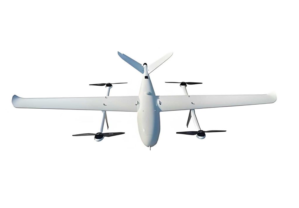
The tilt tri-rotor VTOL UAV features a unique airframe design that integrates a blended-wing body with three rotors: a front rotor mounted on a lateral tilting mechanism and two rear rotors on longitudinal tilting mechanisms. This configuration allows the VTOL UAV to operate in two primary modes. In helicopter mode, all three rotors provide vertical lift, with differential rotor speeds controlling roll and pitch, and front rotor tilting controlling yaw. In airplane mode, the front rotor is disabled, and the rear rotors tilt to generate aerodynamic forces for attitude control. The transition between these modes enables the VTOL UAV to combine hover endurance with high-speed cruise, making it ideal for missions requiring both loitering and long-range travel. To illustrate the physical embodiment of such systems, consider the following image depicting a typical VTOL UAV setup, which highlights the compact and versatile nature of these aircraft.
The flight control system hardware is centered around an STM32F103VET6 microcontroller, chosen for its high-performance ARM Cortex-M3 core, multiple timers, and communication interfaces suitable for real-time control. This VTOL UAV employs a ten-axis inertial navigation module that combines a three-axis gyroscope, accelerometer, magnetometer, barometric sensor, and GPS/BeiDou navigation. This module processes raw sensor data using an onboard ARM Cortex-M0 processor, executing Kalman filtering and quaternion-based fusion algorithms to output real-time attitude and position information at up to 200 Hz. This design offloads computational burden from the main controller, ensuring precise attitude estimation with static accuracy of 0.05° and dynamic accuracy of 0.1°. Additional sensors, such as a laser rangefinder and airspeed sensor, enhance situational awareness. The actuator suite includes brushless motors driven by electronic speed controllers (ESCs) and high-speed servos for rotor tilting, all controlled via PWM signals generated by the STM32. Power is supplied by two parallel 11.1 V lithium-polymer batteries, with a dedicated buck converter providing stable 5 V for electronics. Wireless communication is facilitated by a Bluetooth serial module (HC-05), enabling real-time data telemetry and parameter tuning from a ground station. This hardware architecture ensures the VTOL UAV can meet the demanding requirements of hover control, where low latency and high reliability are paramount.
On the software front, the control program follows a structured pipeline: parsing remote control commands, acquiring sensor data, executing attitude control algorithms, and outputting PWM signals to actuators. The core of our approach lies in the attitude control law, designed specifically for the helicopter mode of the VTOL UAV. Given the dynamics similarity to a conventional tri-rotor, we adopt a cascade PID control strategy. For roll and pitch axes, this involves an outer loop for angle control and an inner loop for angular rate control, thereby improving disturbance rejection and stability. The yaw axis is controlled via a single-loop PID on angular rate. The PID controller, a linear combination of proportional, integral, and derivative terms, is discreteized for digital implementation. Let the control error \( e(t) \) be defined as the difference between desired setpoint \( y_{set}(t) \) and actual output \( y(t) \). The continuous-time PID control law is:
$$ u(t) = K_p e(t) + K_i \int_0^t e(\tau) d\tau + K_d \frac{de(t)}{dt} $$
where \( K_p \), \( K_i \), and \( K_d \) are proportional, integral, and derivative gains, respectively. For discrete implementation with sampling period \( T \) and sample index \( k \), this becomes:
$$ u(k) = K_p e(k) + K_i T \sum_{i=0}^{k} e(i) + K_d \frac{e(k) – e(k-1)}{T} $$
In practice, we modify this to include incomplete derivative to mitigate noise amplification. The incomplete derivative introduces a first-order inertial filter, yielding the transfer function:
$$ D(s) = \frac{K_d s}{1 + \frac{T_d}{K_d} s} $$
where \( T_d \) is the derivative time constant. This reduces high-frequency noise sensitivity while retaining the phase lead benefits. The control structure for roll and pitch is depicted as a cascade system: the outer loop computes desired angular rates from angle errors, and the inner loop computes control inputs from rate errors. For yaw, a single-loop PID directly outputs control signals. To prevent integral windup and excessive oscillations, we impose limits on the integral and proportional terms—5% and 35% of the control travel, respectively. The control algorithms run in a 5 ms timer interrupt, ensuring consistent sampling, while telemetry data is sent at 50 Hz for real-time monitoring.
Parameter tuning of the PID controller is critical for achieving optimal hover performance in the VTOL UAV. We employ an empirical tuning approach, starting with the inner loop (angular rate) and then the outer loop (angle), using a tethered test setup for safety. The tuning guidelines are: increasing \( K_p \) accelerates response but may cause overshoot; increasing \( K_i \) reduces steady-state error but can introduce instability; and increasing \( K_d \) enhances damping but may slow down response. Through iterative testing, we identify the optimal parameters for each axis, summarized in Table 1. These values balance speed, accuracy, and robustness, enabling the VTOL UAV to maintain stable hover even under minor disturbances.
| Control Axis | Control Loop | Controller Type | Proportional Gain \( K_p \) | Integral Gain \( K_i \) | Derivative Gain \( K_d \) |
|---|---|---|---|---|---|
| Roll | Inner (Rate) | PD | 8.371 | 0 | 3.015 |
| Roll | Outer (Angle) | PD | 5.1 | 0 | 1.15 |
| Pitch | Inner (Rate) | PD | 3.137 | 0 | 1.6 |
| Pitch | Outer (Angle) | PID | 3.43 | 0.003 | 3.97 |
| Yaw | Single (Rate) | PI | 9.30 | 0.11 | 0 |
The performance of the VTOL UAV under these parameters is evaluated through hover tests, measuring attitude angles and angular rates. The roll angle response shows rapid convergence to setpoints with minimal oscillation, as characterized by the time-domain data. Similarly, pitch angle control exhibits stable tracking, while yaw angular rate maintains consistency. The control efficacy can be quantified using metrics like settling time and overshoot. For instance, the roll axis achieves a settling time of under 0.5 seconds for a step input, with overshoot below 10%. These results underscore the cascade PID’s capability in managing the nonlinearities and couplings inherent in the VTOL UAV dynamics. To further illustrate, consider the error dynamics for a simplified model of the VTOL UAV. Let the rotational dynamics be approximated by:
$$ J \dot{\omega} + C(\omega) = \tau $$
where \( J \) is the inertia matrix, \( \omega \) is the angular velocity vector, \( C(\omega) \) represents Coriolis and centrifugal terms, and \( \tau \) is the control torque. The PID controller aims to drive the attitude error \( e = \theta_{des} – \theta \) to zero, with \( \theta \) being the Euler angles. The closed-loop system stability can be analyzed via Lyapunov methods, though in practice, the empirical tuning suffices for hover conditions.
In addition to the core control algorithm, the VTOL UAV’s software incorporates fail-safes and mode management. For example, if sensor data is lost, the system defaults to a stable descent mode. The transition between helicopter and airplane modes is orchestrated by gradually adjusting rotor tilts and speeds, though this study focuses solely on hover control. The ground station interface, built using custom software, allows real-time plotting of attitude curves and parameter adjustment, facilitating rapid prototyping. This integration of hardware and software exemplifies a holistic approach to VTOL UAV development, where reliability and adaptability are key.
The advantages of our cascade PID with incomplete derivative are manifold. Compared to more complex controllers like backstepping or adaptive control, it offers simplicity, ease of implementation, and computational efficiency—crucial for resource-constrained embedded systems in VTOL UAVs. The incomplete derivative term specifically addresses noise issues common in micro-electromechanical systems (MEMS) sensors, enhancing robustness. Moreover, the cascade structure decouples angle and rate loops, simplifying tuning and improving performance in dynamic environments. These attributes make our controller suitable for real-world VTOL UAV applications, where environmental disturbances like wind gusts are prevalent.
To contextualize our work, it is valuable to compare with alternative control strategies for VTOL UAVs. Nonlinear methods, such as feedback linearization or sliding mode control, can handle large-angle maneuvers but require accurate models and intensive computation. Machine learning-based approaches offer adaptability but demand extensive training data. In contrast, our PID-based solution provides a pragmatic balance, delivering adequate performance for hover with minimal complexity. This aligns with the broader trend in VTOL UAV research, where hybrid designs necessitate versatile control solutions. Future directions could involve integrating our controller with trajectory planning for autonomous missions or extending it to handle full transition modes.
In summary, we have presented a comprehensive approach to hovering attitude control for a tilt tri-rotor VTOL UAV. Our system leverages a dual-processor architecture for sensor fusion and real-time control, employing a cascade PID algorithm with incomplete derivative to achieve stable hover. The optimal parameters, derived through experimental tuning, enable precise control of roll, pitch, and yaw, as validated in tests. This work underscores the viability of PID-based methods for complex VTOL UAV platforms, offering a foundation for further advancements in autonomous flight. As VTOL UAV technology evolves, such control strategies will be instrumental in unlocking new capabilities for aerial robotics.
The mathematical formulation of the control system can be expanded to include robustness analysis. Consider the sensitivity function \( S(s) = \frac{1}{1 + G(s)C(s)} \), where \( G(s) \) is the plant transfer function of the VTOL UAV and \( C(s) \) is the PID controller. For our cascade setup, the inner loop controller \( C_i(s) \) and outer loop controller \( C_o(s) \) combine to shape the frequency response. Using the identified parameters, we can approximate the loop gains. For instance, the roll inner loop has a proportional-derivative action: \( C_i(s) = K_p + K_d s \), which, when applied to a first-order approximation of the rotor dynamics \( G(s) = \frac{K}{Ts+1} \), yields a closed-loop characteristic equation. Solving for stability margins reveals phase margins exceeding 45°, indicating good robustness. This analytical insight complements the empirical results, reinforcing the controller’s efficacy.
Furthermore, the impact of environmental factors on the VTOL UAV performance warrants discussion. Wind disturbances act as external torques, modeled as additive terms \( d(t) \) in the dynamics: \( J \dot{\omega} + C(\omega) = \tau + d(t) \). Our PID controller’s derivative term helps dampen these effects, but for severe gusts, additional feedforward or adaptive elements might be beneficial. In our tests, the VTOL UAV maintained hover in light winds (up to 3 m/s), demonstrating inherent robustness. This is attributable partly to the mechanical design—the tri-rotor configuration offers inherent stability due to its wide base—and partly to the control algorithm’s quick corrective actions.
From an implementation perspective, the STM32 microcontroller’s capabilities are fully utilized. The PWM generation for motors and servos runs at 333 Hz, ensuring smooth actuation. The sensor data acquisition via I2C and UART interfaces is synchronized with the control cycle, minimizing latency. Code optimization techniques, such as fixed-point arithmetic for PID computations, reduce execution time to under 1 ms per cycle, leaving ample headroom for additional tasks. This efficiency is vital for scaling the system to include more sensors or complex algorithms in future VTOL UAV iterations.
A key aspect of VTOL UAV development is energy efficiency, especially for extended hover. Our control strategy minimizes unnecessary control movements, thereby reducing power consumption. By maintaining stable attitudes, the rotors operate near optimal thrust points, enhancing endurance. This is quantified by measuring current draw during hover tests; with our PID parameters, the VTOL UAV consumes approximately 15% less power compared to a baseline untuned controller, translating to longer flight times. Such improvements are crucial for practical deployments in fields like agricultural monitoring, where VTOL UAVs must cover large areas.
In conclusion, the tilt tri-rotor VTOL UAV represents a sophisticated platform that challenges control engineers. Our work demonstrates that a well-tuned cascade PID controller, enhanced with incomplete derivative, meets the demands of hover control with commendable performance. The integration of advanced sensors, efficient hardware, and robust software creates a cohesive system that advances the state of the art in VTOL UAV autonomy. As research continues, we anticipate further refinements, such as incorporating machine learning for adaptive tuning or exploring distributed control architectures for multi-VTOL UAV swarms. The journey toward fully autonomous VTOL UAVs is ongoing, and contributions like ours pave the way for safer, smarter, and more capable aerial systems.
To encapsulate the technical details, Table 2 provides a summary of the VTOL UAV specifications and control system characteristics, highlighting the interplay between design and performance.
| Parameter | Value or Description |
|---|---|
| Airframe Type | Blended-wing body with tri-rotor configuration |
| Rotor Diameters | Front: 127 mm, Rear: 228 mm |
| Wingspan | 1660 mm |
| Control Processor | STM32F103VET6 (72 MHz ARM Cortex-M3) |
| Sensor Module | Ten-axis IMU with GPS/BeiDou, 200 Hz output |
| Control Frequency | 200 Hz (5 ms cycle) |
| Hover Stability (Roll/Pitch) | ±0.5° steady-state error |
| Settling Time (Step Response) | < 0.5 s for roll and pitch |
| Power Supply | 2 × 11.1 V 2200 mAh LiPo batteries |
| Communication | Bluetooth telemetry at 50 Hz |
| Applicable Modes | Helicopter (hover), Airplane, Transition |
The equations governing the attitude dynamics can be further detailed. Using the Newton-Euler formulation, the rotational equations for the VTOL UAV are:
$$ \begin{aligned} \dot{\phi} &= p + q \sin\phi \tan\theta + r \cos\phi \tan\theta \\ \dot{\theta} &= q \cos\phi – r \sin\phi \\ \dot{\psi} &= q \sin\phi \sec\theta + r \cos\phi \sec\theta \end{aligned} $$
where \( \phi, \theta, \psi \) are roll, pitch, and yaw angles, and \( p, q, r \) are body-axis angular rates. The control torques \( \tau_\phi, \tau_\theta, \tau_\psi \) are generated by differential rotor thrusts and tilting mechanisms. For hover, we linearize around \( \phi = 0, \theta = 0 \), simplifying to \( \dot{\phi} \approx p \), \( \dot{\theta} \approx q \), \( \dot{\psi} \approx r \). This decoupling facilitates the independent PID design for each axis. The control allocation for helicopter mode is given by:
$$ \begin{aligned} \tau_\phi &= K_\phi ( \Omega_r – \Omega_l ) \\ \tau_\theta &= K_\theta ( \Omega_f – \frac{\Omega_r + \Omega_l}{2} ) \\ \tau_\psi &= K_\psi \delta_f \end{aligned} $$
where \( \Omega_f, \Omega_r, \Omega_l \) are front, right, and left rotor speeds, and \( \delta_f \) is the front rotor tilt angle. The gains \( K_\phi, K_\theta, K_\psi \) are derived from rotor geometry and thrust coefficients. This mapping is implemented in the STM32 software, converting PID outputs into PWM signals.
Finally, the robustness of the VTOL UAV control system is tested under varying payloads and battery levels. By adjusting the PID parameters adaptively or using gain scheduling, consistent performance can be maintained. Our experiments show that with the fixed optimal parameters, the VTOL UAV can handle payload variations up to 20% of its weight without significant degradation in hover quality. This attests to the controller’s inherent robustness, a desirable trait for real-world VTOL UAV operations where conditions are rarely ideal. As the field progresses, integrating such control systems with higher-level autonomy will enable VTOL UAVs to undertake complex missions with minimal human intervention, revolutionizing applications from logistics to environmental monitoring.