
The operational envelope of quadrotor unmanned aerial vehicles (UAVs) continues to expand, encompassing critical applications from infrastructure inspection and precision agriculture to last-mile delivery and emergency response. However, this increased reliance on drone technology brings to the fore a fundamental vulnerability: their flight stability is acutely dependent on the integrity of all four rotors. A quadrotor is a quintessential under-actuated, strongly coupled nonlinear system. The partial or complete failure of a single rotor instantly disrupts the delicate equilibrium of forces and moments, typically leading to uncontrolled tumbling and a crash within seconds if no corrective action is taken. Developing robust Fault-Tolerant Control (FTC) strategies is therefore not merely an academic exercise but a critical prerequisite for deploying UAV drones in safety-critical urban airspace or for payload transportation, where such failures could lead to significant property damage or personal injury. This paper addresses this paramount challenge by proposing a novel, hierarchical adaptive control framework designed to maintain stability and precise trajectory tracking across a spectrum of failure modes, from nominal operation to a complete single-rotor loss.
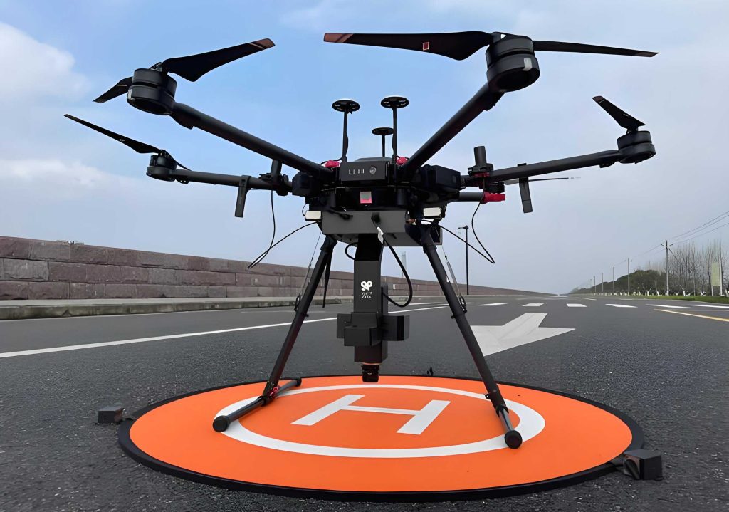
Existing approaches to UAV drone fault tolerance often face significant limitations. Classical methods like PID or LQR, while foundational, lack the robustness to handle the severe nonlinearities and large attitude excursions induced by a rotor failure. Advanced nonlinear robust controllers, such as Sliding Mode Control (SMC), introduce chattering that can stress the remaining healthy actuators, potentially exacerbating the failure. Conversely, control methods like backstepping can suffer from “complexity explosion,” making them computationally prohibitive for real-time implementation on embedded flight controllers. Data-driven methods, including Reinforcement Learning (RL), show promise but often grapple with the “simulation-to-reality” gap and may lack stability guarantees in the extreme, out-of-distribution flight regimes caused by failures.
Model-based strategies like Nonlinear Model Predictive Control (NMPC) excel at handling constraints and optimizing performance but are highly sensitive to model inaccuracies, which are magnified during faulty, high-rate rotations. Incremental Nonlinear Dynamic Inversion (INDI) reduces model dependency by using sensor feedback but still requires an accurate control effectiveness matrix. Crucially, many state-of-the-art FTC demonstrations rely on external motion capture systems (e.g., VICON) for high-fidelity state estimation, masking the challenges posed by real-world onboard sensors with noise, latency, and lower update rates. This dependency limits the practical applicability and generalizability of these methods. To systematically overcome these intertwined challenges, we propose a layered control architecture that synergistically combines the predictive and constraint-handling power of a Dynamic Weighting NMPC (DWNMPC) with the robustness and adaptability of an Adaptive INDI (AINDI). The core contributions of this work are: 1) A DWNMPC formulation featuring a state-dependent weight adaptation mechanism that autonomously shifts priority from survival-oriented attitude stabilization to precision trajectory tracking. 2) An AINDI controller enhanced with online Recursive Least Squares (RLS)-based parameter identification to compensate for model uncertainties and aerodynamic disturbances in real-time. 3) Experimental validation of the complete hierarchical framework on a physical quadrotor platform using only onboard sensors, demonstrating effective control through no-fault, partial-failure, and complete single-rotor failure scenarios during dynamic trajectory tracking.
System Modeling and Problem Formulation
Accurate dynamic modeling is the cornerstone of model-based control. We consider a standard “X” configuration quadrotor UAV drone. Let ${W} = {x_W, y_W, z_W}$ denote the world-fixed inertial frame and ${B} = {x_B, y_B, z_B}$ denote the body-fixed frame attached to the drone’s center of mass. The drone’s state is described by its position $mathbf{p}_W = [x, y, z]^T$, velocity $mathbf{v}_W = [v_x, v_y, v_z]^T$ (in ${W}$), attitude quaternion $mathbf{q}_{WB} = [q_w, q_x, q_y, q_z]^T$ (representing the rotation from ${B}$ to ${W}$), and body angular rate $boldsymbol{omega}_B = [p, q, r]^T$ (in ${B}$). The rotors generate thrusts $mathbf{f} = [f_1, f_2, f_3, f_4]^T$.
The complete nonlinear dynamics, incorporating translational and rotational drag, are given by:
$$
\begin{align*}
\dot{\mathbf{p}}_W &= \mathbf{v}_W \\
\dot{\mathbf{v}}_W &= \mathbf{g} + \mathbf{q}_{WB} \odot \mathbf{c}_B – k_{td} \mathbf{v}_W \\
\dot{\mathbf{q}}_{WB} &= \frac{1}{2} \Lambda(\boldsymbol{\omega}_B) \mathbf{q}_{WB} \\
\mathbf{I}_v \dot{\boldsymbol{\omega}}_B &= \boldsymbol{\tau}_B – k_{rd} \boldsymbol{\omega}_B – \boldsymbol{\omega}_B \times \mathbf{I}_v \boldsymbol{\omega}_B + \boldsymbol{\tau}_{ext}
\end{align*}
$$
Here, $mathbf{g}=[0,0,-g]^T$ is gravity, $mathbf{c}_B = [0,0, C]^T$ with $C = (\sum_{i=1}^4 f_i)/m$ is the mass-normalized thrust vector, and $odot$ denotes the quaternion rotation operation. $k_{td}$ and $k_{rd}$ are translational and rotational drag coefficients, respectively. $mathbf{I}_v = text{diag}(I_{xx}, I_{yy}, I_{zz})$ is the inertia tensor. The control torque $boldsymbol{tau}_B$ and total thrust $F$ are related to the individual rotor thrusts via the control allocation matrix $mathbf{G}$:
$$
\begin{bmatrix} F \\ \boldsymbol{\tau}_B \end{bmatrix} = \mathbf{G} \mathbf{f}, \quad \mathbf{G} = \begin{bmatrix}
1 & 1 & 1 & 1 \\
r_{y1} & r_{y2} & r_{y3} & r_{y4} \\
-r_{x1} & -r_{x2} & -r_{x3} & -r_{x4} \\
-k_t & k_t & -k_t & k_t
\end{bmatrix}
$$
where $(r_{xi}, r_{yi})$ are the coordinates of rotor $i$ in ${B}$, and $k_t$ is the torque-to-thrust coefficient. The term $boldsymbol{tau}_{ext}$ represents unmodeled torques from aerodynamic effects and model mismatch. First-order dynamics $dot{f}_i = (u_i – f_i)/sigma$ are used to model the transient response of the motors to command $u_i$, with time constant $sigma$.
The FTC problem is formulated as follows: Design a control law $mathbf{u} = [u_1, u_2, u_3, u_4]^T$ such that 1) Under no failure, the UAV drone tracks a desired trajectory precisely. 2) Under partial or complete failure of one rotor (modeled by a fault coefficient $k_i in [0,1]$ scaling the $i$-th rotor’s maximum thrust), the controller reconfigures to maintain stability and continue trajectory tracking as accurately as possible, acknowledging that yaw control must be sacrificed to preserve roll/pitch authority.
Hierarchical Adaptive Fault-Tolerant Controller Design
The proposed control architecture is hierarchically structured, leveraging the strengths of both optimization-based and incremental control paradigms. The high-level DWNMPC plans optimal thrust commands over a horizon, accounting for constraints and the fault condition. The low-level AINDI then rapidly adjusts these commands using immediate sensor feedback to compensate for dynamic model errors and disturbances. This synergy creates a resilient controller adaptable to various failure modes.
Upper Layer: Dynamic Weighting Nonlinear Model Predictive Control (DWNMPC)
The DWNMPC controller solves a finite-horizon optimal control problem online. The state vector is $mathbf{x} = [mathbf{p}_W^T, mathbf{q}_{WB}^T, mathbf{v}_W^T, boldsymbol{omega}_B^T, mathbf{f}^T]^T$ and the control input is $mathbf{u}$. The system dynamics $dot{mathbf{x}} = f(mathbf{x}, mathbf{u})$ are discretized with sampling time $Delta t$ over a prediction horizon $N$. At each step, DWNMPC minimizes a cost function subject to dynamics and input constraints:
$$
\begin{aligned}
\min_{\mathbf{u}} & \quad \mathbf{x}_N^T \mathbf{Q}_N \mathbf{x}_N + \sum_{k=0}^{N-1} \left( \mathbf{x}_k^T \mathbf{Q}(\mathbf{x}_k) \mathbf{x}_k + \mathbf{u}_k^T \mathbf{R}(\mathbf{x}_k) \mathbf{u}_k \right) \\
\text{s.t.} & \quad \mathbf{x}_{k+1} = f_d(\mathbf{x}_k, \mathbf{u}_k), \\
& \quad \mathbf{u}_{min} \preceq \mathbf{u}_k \preceq \mathbf{u}_{max}.
\end{aligned}
$$
The key innovation lies in the state-dependent weight matrices $mathbf{Q}(mathbf{x}_k)$ and $mathbf{R}(mathbf{x}_k)$. After a rotor failure, the primary objective shifts instantly from precise tracking to preventing a catastrophic flip. Our DWNMPC embodies this by dynamically adjusting weights based on the current attitude error. We decompose the attitude error quaternion $mathbf{q}_e = mathbf{q}_{ref}^{-1} odot mathbf{q}$ into a controllable tilt component $mathbf{q}_{xy}$ (roll/pitch) and an uncontrollable yaw component $mathbf{q}_z$. The tilt error magnitude $| mathbf{q}_{xy} |$ serves as the primary indicator of “emergency.”
The weight adaptation functions are designed as follows:
- Position/Weights $Q_p$: Reduced when tilt error is large to avoid aggressive, destabilizing positional corrections.
$$ Q_p(mathbf{x}_k) = \frac{Q_{p,max}}{1 + k_p \cdot | \mathbf{q}_{xy} |^2} $$ - Tilt Attitude Weights $Q_{xy}$: Increased significantly during large errors to prioritize attitude recovery.
$$ Q_{xy}(mathbf{x}_k) = Q_{xy,base} + k_{xy} \cdot | \mathbf{q}_{xy} |^2 $$ - Yaw Attitude Weights $Q_{z}$: Set to zero under failure ($k_i < 1$) to ignore uncontrollable yaw error, freeing control effort for stabilized axes.
- Angular Rate Weights $Q_{omega}$: Increased to penalize high rotation rates and dampen the tumble.
$$ Q_{\omega}(mathbf{x}_k) = Q_{\omega,base} + k_{\omega} \cdot | \mathbf{q}_{xy} |^2 $$ - Control Input Weights $mathbf{R}$: Lowered during large errors to allow the motors to saturate if necessary for recovery.
$$ \mathbf{R}(\mathbf{x}_k) = \mathbf{R}_{max} – (\mathbf{R}_{max} – \mathbf{R}_{min}) \cdot \tanh(k_R \cdot \text{ErrorNorm}(\mathbf{x}_k)) $$
This dynamic strategy allows the UAV drone controller to operate in multiple implicit modes: Emergency (high attitude weights, low position/input weights), Transition (balanced weights), and Steady-state (high position/input weights, moderate attitude weights), ensuring smooth and context-aware control.
Lower Layer: Adaptive Incremental Nonlinear Dynamic Inversion (AINDI)
While DWNMPC provides optimized commands, its performance can degrade under significant model uncertainty. The AINDI layer acts as a high-frequency, adaptive inner-loop controller that robustly tracks the desired angular acceleration $boldsymbol{alpha}_d$ from DWNMPC.
INDI leverages sensor measurements to cancel nonlinearities and disturbances. The angular acceleration dynamics can be approximated using filtered sensor signals (denoted by superscript $f$):
$$
\mathbf{I}_v \dot{\boldsymbol{\omega}}_B \approx \boldsymbol{\tau}_B – \boldsymbol{\tau}_B^f + \mathbf{I}_v \dot{\boldsymbol{\omega}}_B^f
$$
The desired torque $boldsymbol{tau}_{B,d}$ is then computed to achieve $dot{boldsymbol{omega}}_{B,d} = boldsymbol{alpha}_d$:
$$
\boldsymbol{\tau}_{B,d} = \boldsymbol{\tau}_B^f + \mathbf{I}_v (\boldsymbol{\alpha}_d – \dot{\boldsymbol{\omega}}_B^f)
$$
Finally, the actuator commands are computed using the pseudo-inverse of a fault-adjusted control effectiveness matrix $hat{mathbf{G}}$ (with the column corresponding to the failed rotor set to zero):
$$
\mathbf{u}_{aindi} = \hat{\mathbf{G}}^{\dagger} \begin{bmatrix} F_d \\ \boldsymbol{\tau}_{B,d} \end{bmatrix}
$$
To enhance robustness against inertia and drag parameter errors, we embed an online parameter estimator. The rotational dynamics are reformulated into a linear regression model:
$$
\boldsymbol{\tau}_B = \underbrace{\begin{bmatrix}
\dot{p} & -r q & q r & p \\
q r & \dot{q} & -p r & q \\
-p q & p q & \dot{r} & r
\end{bmatrix}}_{\boldsymbol{\Phi}(\boldsymbol{\omega}_B, \dot{\boldsymbol{\omega}}_B)} \underbrace{\begin{bmatrix} I_{xx} \\ I_{yy} \\ I_{zz} \\ k_{rd} \end{bmatrix}}_{\boldsymbol{\theta}} + \boldsymbol{\tau}_{ext}
$$
A Recursive Least Squares (RLS) algorithm with forgetting factor $lambda$ is used to continuously update the parameter estimate $hat{boldsymbol{theta}}_k$:
$$
\begin{aligned}
\mathbf{K}_k &= \mathbf{P}_{k-1} \boldsymbol{\Phi}_k^T ( \lambda \mathbf{I} + \boldsymbol{\Phi}_k \mathbf{P}_{k-1} \boldsymbol{\Phi}_k^T )^{-1} \\
\hat{\boldsymbol{\theta}}_k &= \hat{\boldsymbol{\theta}}_{k-1} + \mathbf{K}_k ( \boldsymbol{\tau}_B – \boldsymbol{\Phi}_k \hat{\boldsymbol{\theta}}_{k-1} ) \\
\mathbf{P}_k &= \frac{1}{\lambda} ( \mathbf{I} – \mathbf{K}_k \boldsymbol{\Phi}_k ) \mathbf{P}_{k-1}
\end{aligned}
$$
The updated inertia estimate $hat{mathbf{I}}_v$ is then used in the AINDI torque calculation, enabling the UAV drone controller to adapt to changes in mass distribution or poorly known dynamics.
Experimental Validation and Results
The proposed hierarchical FTC system was implemented and tested on a custom-built quadrotor UAV drone platform (mass: 1.505 kg, arm length: ~0.145 m). All algorithms ran in real-time on an onboard NVIDIA Jetson Orin NX computer communicating with a Pixhawk flight controller at 125 Hz. State estimation was performed solely by the onboard EKF fusing IMU and GPS data, mimicking real-world conditions without external motion capture. The controller was evaluated in three progressively challenging scenarios: nominal operation, partial rotor failure (90% thrust loss), and complete rotor failure (100% loss), all while tracking a circular trajectory of 2 m radius at 0.5 m/s.
1. No-Fault Operation: The controller demonstrated stable and precise tracking. The RMS tracking errors were low, establishing a performance baseline. The dynamic weights remained in steady-state mode, prioritizing smooth, accurate flight.
2. Partial Rotor Failure (90% Loss): Upon the injected failure, the DWNMPC’s weight adaptation mechanism immediately shifted to emergency mode. The position weights were suppressed, while attitude and angular rate weights were heightened. This allowed the controller to prioritize arresting the incipient roll/pitch motion. After stabilization (with the UAV drone entering a controlled yaw spin), the weights transitioned, and the drone successfully continued tracking the circle with only a minor increase in tracking error compared to the no-fault case. The AINDI layer effectively compensated for the disturbed dynamics.
3. Complete Rotor Failure (100% Loss): This represents the most severe single-point failure. The proposed method successfully stabilized the UAV drone, preventing a crash. The drone entered a stable high-rate yaw spin (approximately -10.5 rad/s) as expected. Crucially, it maintained controlled flight and continued to follow the reference trajectory, albeit with increased tracking error due to the strong gyroscopic coupling and reduced lift efficiency. The RLS-based adaptation within AINDI was crucial here, adjusting the inertia estimates online to account for the highly nonlinear flight regime.
The following table summarizes the quantitative trajectory tracking performance in terms of Root Mean Square Error (RMSE):
| Control Method | Failure Severity | RMSE X (m) | RMSE Y (m) | RMSE Z (m) |
|---|---|---|---|---|
| Proposed Method | 0% (No Fault) | 0.0911 | 0.0801 | 0.0078 |
| Baseline NMPC | 0% (No Fault) | 0.1270 | 0.1172 | 0.0144 |
| Proposed Method | 90% (Partial) | 0.1080 | 0.1019 | 0.0222 |
| Baseline NMPC | 90% (Partial) | 0.1091 | 0.1054 | 0.0499 |
| Proposed Method | 100% (Complete) | 0.1387 | 0.1346 | 0.0908 |
| Baseline NMPC | 100% (Complete) | Diverged / Crashed | Diverged / Crashed | Diverged / Crashed |
Ablation studies confirmed the necessity of both components: disabling the dynamic weight adaptation led to poor recovery from large initial errors post-failure, and disabling the RLS estimator caused instability under conditions of model mismatch (simulated by adding an unmodeled payload). The proposed integrated framework proved robust to both state uncertainty and parameter uncertainty.
Conclusion and Future Work
This paper presented a hierarchical adaptive multi-mode fault-tolerant control strategy for quadrotor UAV drones. The method seamlessly integrates a high-level DWNMPC with state-dependent weight adaptation and a low-level AINDI with online parameter identification. The DWNMPC provides intelligent, constraint-aware command generation that dynamically balances survival and performance objectives. The AINDI layer delivers robust, adaptive tracking that compensates for model deficiencies and disturbances. Extensive real-world experiments validated the approach, demonstrating safe and controlled flight under no-fault, partial rotor failure, and complete rotor failure conditions using only onboard sensors.
The results show that a UAV drone equipped with this controller can survive a severe actuator fault and maintain a remarkable degree of trajectory tracking capability. The increase in RMSE from the no-fault to the complete-failure case was measured to be only 0.0476 m, 0.0545 m, and 0.083 m in the X, Y, and Z axes, respectively, underscoring the effectiveness of the trade-off between fault tolerance and tracking precision. This work provides a practical, high-performance software-based FTC solution for existing quadrotor platforms without requiring hardware redundancy.
Future work will focus on formal stability analysis of the interconnected nonlinear adaptive system. Furthermore, exploring hardware redundancy through hybrid actuation (e.g., combining rotors with aerodynamic control surfaces) could potentially restore full attitude control, including yaw, after a rotor failure, opening avenues for even more capable fault-tolerant UAV drone systems.