
The study and application of drone formation flight, particularly for multi-rotor unmanned aerial vehicles (UAVs), represent a significant frontier in modern aerospace research. While individual drones offer flexibility, a coordinated drone formation enables the execution of complex tasks beyond the capability of a single agent, such as large-scale surveillance, precision agricultural monitoring, and collaborative payload transport. However, maintaining a stable and precise drone formation in real-world environments is fraught with challenges, including external aerodynamic disturbances, inherent model coupling, and potential actuator failures. This paper addresses these critical issues by proposing a comprehensive, fault-tolerant control framework. The core of our approach integrates an Extended State Observer (ESO) for the real-time estimation and aggregation of total disturbances with a Robust Global Fast Terminal Sliding Mode Controller (RGFTSMC) designed for finite-time convergence and strong robustness. The control architecture is then extended to a multi-agent system using a leader-follower strategy to achieve the desired cooperative drone formation.
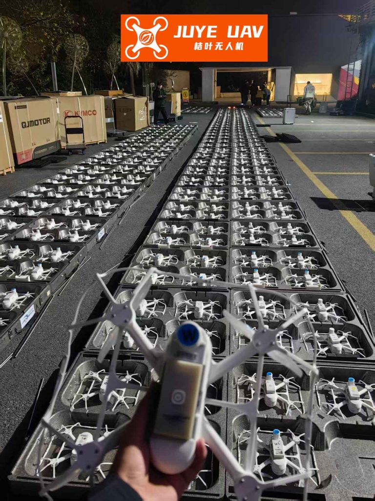
Coordinated flight in a drone formation requires sophisticated control strategies to manage the spatial relationships between vehicles. Numerous methods have been explored, including the leader-follower approach, virtual structure, behavior-based methods, and artificial potential fields. Among these, the leader-follower strategy offers a conceptually straightforward and effective framework for drone formation control. However, the practical deployment of any drone formation is susceptible to performance degradation or catastrophic failure due to unforeseen events. Actuator faults, such as partial loss of effectiveness or bias, are particularly critical. Simultaneously, external wind gusts and the complex, coupled nonlinear dynamics of quadrotors present persistent disturbances. While existing research has made progress in formation control or fault tolerance individually, a unified strategy that ensures robust drone formation integrity under the simultaneous influence of actuator faults and compounded disturbances remains a vital area for development. Our work aims to fill this gap by designing a controller that is inherently tolerant to faults and disturbances, ensuring the drone formation can maintain its mission profile even under adverse conditions.
System Modeling with Actuator Faults and Disturbances
We begin by establishing the nonlinear dynamic model for a quadrotor UAV, explicitly incorporating terms for external disturbances and actuator faults. The vehicle is treated as a rigid body with symmetrical structure. Two coordinate frames are defined: the inertial earth frame \(O_E(X, Y, Z)\) and the body-fixed frame \(O_B(x_b, y_b, z_b)\). The system states are the position \([x, y, z]^T\) and the Euler angles \([\phi, \theta, \psi]^T\) (roll, pitch, yaw). The control inputs are derived from the thrusts of the four rotors.
An actuator fault is modeled as an additive bias on the nominal control signal. For the \(r\)-th actuator (\(r=1,2,3,4\)):
$$ U_r = U_{r}^a + f_r $$
where \(U_{r}^a\) is the fault-free control input and \(f_r\) is an unknown bounded fault signal. When \(f_r \neq 0\), the actuator is in a faulty condition.
Applying the Newton-Euler formalism, the complete 6-DOF model under faults and disturbances is:
$$
\begin{aligned}
\ddot{x} &= \frac{1}{m} (\cos\phi \sin\theta \cos\psi + \sin\phi \sin\psi) U_1 – \frac{k_x}{m} \dot{x} + d_x \\
\ddot{y} &= \frac{1}{m} (\cos\phi \sin\theta \sin\psi – \sin\phi \cos\psi) U_1 – \frac{k_y}{m} \dot{y} + d_y \\
\ddot{z} &= \frac{1}{m} (\cos\phi \cos\theta) U_1 – g – \frac{k_z}{m} \dot{z} + d_z \\
\ddot{\phi} &= \frac{I_{yy} – I_{zz}}{I_{xx}} \dot{\theta}\dot{\psi} + \frac{d}{I_{xx}} U_{2}^a – \frac{k_\phi}{I_{xx}} \dot{\phi} + \frac{J_r}{I_{xx}} \dot{\theta} \Omega + d_\phi + \frac{d}{I_{xx}} f_2 \\
\ddot{\theta} &= \frac{I_{zz} – I_{xx}}{I_{yy}} \dot{\phi}\dot{\psi} + \frac{d}{I_{yy}} U_{3}^a – \frac{k_\theta}{I_{yy}} \dot{\theta} + \frac{J_r}{I_{yy}} \dot{\phi} \Omega + d_\theta + \frac{d}{I_{yy}} f_3 \\
\ddot{\psi} &= \frac{I_{xx} – I_{yy}}{I_{zz}} \dot{\phi}\dot{\theta} + \frac{1}{I_{zz}} U_{4}^a – \frac{k_\psi}{I_{zz}} \dot{\psi} + d_\psi + \frac{1}{I_{zz}} f_4
\end{aligned}
$$
where \(m\) is the mass, \(I_{xx}, I_{yy}, I_{zz}\) are moments of inertia, \(k_{(\cdot)}\) are aerodynamic drag coefficients, \(d\) is the arm length, \(J_r\) is the rotor inertia, \(\Omega\) is the sum of rotor speeds, \(g\) is gravity, and \(d_x, d_y, d_z, d_\phi, d_\theta, d_\psi\) represent external disturbances.
The model parameters used for simulation are summarized in the table below.
| Parameter | Symbol | Value | Unit |
|---|---|---|---|
| Mass | \(m\) | 2.0 | kg |
| Inertia (X,Y) | \(I_{xx}, I_{yy}\) | 1.250 | N·m·s²/rad |
| Inertia (Z) | \(I_{zz}\) | 1.250 | N·m·s²/rad |
| Arm Length | \(d\) | 0.25 | m |
| Drag Coefficient | \(k_x, k_y, k_z\) | 0.01 | N·s/m |
| Drag Coefficient | \(k_\phi, k_\theta, k_\psi\) | 1.49e-7 | N·m·s/rad |
| Rotor Inertia | \(J_r\) | 1.0e-3 | N·m·s²/rad |
Design of the Robust Global Fast Terminal Sliding Mode Controller (RGFTSMC)
The proposed control structure is dual-layered. First, an ESO is designed to estimate the “total disturbance” affecting each channel, which lumps together model uncertainties, external disturbances, and the effects of actuator faults. Second, a RGFTSMC uses these estimates to compensate for the disturbances and achieve finite-time tracking.
Extended State Observer (ESO) Design
Consider the pitch channel dynamics, which can be rewritten in state-space form with an extended state:
$$
\begin{aligned}
\dot{x}_1 &= x_2 \\
\dot{x}_2 &= f_\theta(\mathbf{x}) + b_\theta U_{3}^a + \tilde{f}_\theta
\end{aligned}
$$
where \(x_1 = \theta\), \(x_2 = \dot{\theta}\), \(b_\theta = d/I_{yy}\), \(f_\theta(\mathbf{x})\) contains known coupling terms, and \(\tilde{f}_\theta\) is the extended state representing the sum of unknown disturbances and the fault effect: \(\tilde{f}_\theta = d_\theta + (d/I_{yy}) f_3\).
We construct a linear ESO for this system:
$$
\begin{aligned}
\dot{\hat{x}}_1 &= \hat{x}_2 + \frac{\alpha_1}{\epsilon} (x_1 – \hat{x}_1) \\
\dot{\hat{x}}_2 &= b_\theta U_{3}^a + \hat{x}_3 + \frac{\alpha_2}{\epsilon^2} (x_1 – \hat{x}_1) \\
\dot{\hat{x}}_3 &= \frac{\alpha_3}{\epsilon^3} (x_1 – \hat{x}_1)
\end{aligned}
$$
Here, \(\hat{x}_1\) and \(\hat{x}_2\) estimate the states, and \(\hat{x}_3\) estimates the total disturbance \(\tilde{f}_\theta\). The parameters \(\alpha_1, \alpha_2, \alpha_3\) are chosen so that the polynomial \(s^3 + \alpha_1 s^2 + \alpha_2 s + \alpha_3\) is Hurwitz. The parameter \(0 < \epsilon < 1\) is a small gain that determines the observer bandwidth. A smaller \(\epsilon\) leads to faster estimation but increases sensitivity to measurement noise. The convergence of the estimation error to a bounded region can be proven via Lyapunov analysis under the assumption that the derivative of the total disturbance is bounded.
| Observer Gain | Value |
|---|---|
| \(\alpha_1\) | 0.3 |
| \(\alpha_2\) | 4.0 |
| \(\alpha_3\) | 8.0 |
| \(\epsilon\) | 0.01 |
Attitude and Position Fault-Tolerant Controller
For the pitch channel, define the tracking error \(e_\theta = \theta – \theta_d\). A Global Fast Terminal Sliding Mode (GFTSM) surface is chosen:
$$
s_\theta = \dot{e}_\theta + \mu_\theta e_\theta + \eta_\theta |e_\theta|^{\gamma_\theta} \text{sign}(e_\theta)
$$
where \(\mu_\theta, \eta_\theta > 0\), and \(\gamma_\theta = p_\theta/q_\theta\) with \(p_\theta, q_\theta\) positive odd integers satisfying \(0 < \gamma_\theta < 1\). This surface guarantees finite-time convergence of both the sliding phase and the reaching phase from any initial state.
To reduce the chattering inherent in standard sliding mode control, we replace the discontinuous signum function with a continuous function \(\Xi(s)\):
$$
\Xi(s) = \frac{s}{|s| + \rho}
$$
where \(\rho > 0\) is a small constant. This function retains a high gain near the sliding surface \(s=0\) but remains continuous, significantly attenuating chattering.
We select the reaching law:
$$
\dot{s}_\theta = -k_\theta s_\theta – \delta_\theta \Xi(s_\theta)
$$
with \(k_\theta, \delta_\theta > 0\). Using the dynamics and the disturbance estimate \(\hat{x}_3 \approx \tilde{f}_\theta\) from the ESO, the fault-tolerant control law is derived:
$$
U_{3}^a = \frac{1}{b_\theta} \left[ \ddot{\theta}_d – \hat{x}_3 – \mu_\theta \dot{e}_\theta – \eta_\theta \gamma_\theta |e_\theta|^{\gamma_\theta – 1} \dot{e}_\theta – k_\theta s_\theta – \delta_\theta \Xi(s_\theta) \right]
$$
The stability and finite-time convergence can be proved by selecting the Lyapunov function \(V = \frac{1}{2} s_\theta^2\) and showing that its derivative satisfies \(\dot{V} \leq -\kappa V^{\frac{1}{2}}\) for some \(\kappa > 0\), which implies convergence to \(s_\theta=0\) in finite time. The controllers for roll (\(U_{2}^a\)) and yaw (\(U_{4}^a\)) are designed analogously.
The position controllers are designed in a similar manner but generate virtual control inputs. For the \(z\)-channel, defining \(e_z = z – z_d\) and its sliding surface \(s_z\), the control law is:
$$
u_{1z} = m \left[ \ddot{z}_d – \hat{f}_z – \mu_z \dot{e}_z – \eta_z \gamma_z |e_z|^{\gamma_z – 1} \dot{e}_z + g – k_z s_z – \delta_z \Xi(s_z) \right]
$$
where \(\hat{f}_z\) is the ESO estimate for the position channel’s total disturbance. The total thrust \(U_1\) and desired roll/pitch angles \((\phi_d, \theta_d)\) are then computed from the virtual controls \([u_{1x}, u_{1y}, u_{1z}]^T\) using the standard transformation for quadrotors:
$$
\begin{aligned}
U_1 &= \frac{m}{\cos\phi_d \cos\theta_d} u_{1z} \\
\phi_d &= \arctan\left( \frac{\cos\theta_d (\sin\psi_d \cdot u_{1x} – \cos\psi_d \cdot u_{1y})}{u_{1z}} \right) \\
\theta_d &= \arctan\left( \frac{\cos\psi_d \cdot u_{1x} + \sin\psi_d \cdot u_{1y}}{u_{1z}} \right)
\end{aligned}
$$
The desired yaw angle \(\psi_d\) is independently specified. This hierarchical control structure ensures that the position commands are translated into feasible attitude commands for the inner-loop RGFTSMC.
| Controller Parameter | Attitude Channel Value | Position Channel Value |
|---|---|---|
| \(\mu\) | 15 | 1.0 |
| \(\eta\) | 13 | 1.0 |
| \(\gamma = p/q\) | 13/15 | 13/15 |
| \(k\) | 60 | 5.0 |
| \(\delta\) | Tuned based on disturbance bound | Tuned based on disturbance bound |
| \(\rho\) (in \(\Xi(s)\)) | 0.05 | 0.05 |
Leader-Follower Cooperative Control for Drone Formation
To orchestrate the motion of multiple drones into a specific geometric drone formation, we employ the leader-follower strategy. This method is computationally efficient and provides clear stability guarantees. We consider a drone formation consisting of one leader and \(N\) followers. The control objective for each follower is to maintain a prescribed relative position with respect to the leader.
For a follower \(F\) and the leader \(L\), the desired formation is defined by a constant offset vector \((d_x^{des}, d_y^{des})\) in the leader’s body frame. The actual relative position in the horizontal plane is given by:
$$
\begin{aligned}
d_x^{LF} &= (x_F – x_L)\cos\psi_L + (y_F – y_L)\sin\psi_L \\
d_y^{LF} &= -(x_F – x_L)\sin\psi_L + (y_F – y_L)\cos\psi_L
\end{aligned}
$$
The formation tracking errors are:
$$
e_x = d_x^{LF} – d_x^{des}, \quad e_y = d_y^{LF} – d_y^{des}
$$
Differentiating these errors yields a system that can be controlled by the follower’s linear velocity \(v_F\) and angular rate \(\Omega_F\). We design a first-order sliding mode controller for this subsystem. Defining a sliding surface \(\mathbf{s}_f = [s_x, s_y]^T = \mathbf{K} [e_x, e_y]^T\) with positive definite gain matrix \(\mathbf{K}\), we choose the reaching law \(\dot{\mathbf{s}}_f = -\Lambda \Xi(\mathbf{s}_f)\), where \(\Lambda > 0\) and \(\Xi(\cdot)\) is the continuous function defined earlier. This leads to the formation control law for the follower:
$$
\begin{bmatrix} v_F \\ \Omega_F \end{bmatrix} = \mathbf{B}^{-1} \left( -\Lambda \Xi(\mathbf{s}_f) – \mathbf{K} \mathbf{A} \right)
$$
where matrices \(\mathbf{A}\) and \(\mathbf{B}\) come from the error dynamics. This control output \((v_F, \Omega_F)\) is then translated into reference trajectories \((x_{F,d}, y_{F,d}, \psi_{F,d})\) for the follower’s low-level RGFTSMC, closing the loop for the entire drone formation.
Simulation Results and Analysis
To validate the proposed ESO-RGFTSMC framework for fault-tolerant drone formation flight, extensive numerical simulations were conducted. A scenario with one leader and two followers was established. The communication topology was defined such that both followers receive state information from the leader. The desired formation was a “V” shape with specific offsets.
A severe fault and disturbance profile was injected into the leader’s dynamics to test the robustness of the entire drone formation:
1. For \(t < 5s\): Nominal operation.
2. At \(t = 5s\): Step external disturbances are applied to all translational and rotational channels.
3. At \(t = 10s\): Simultaneous actuator bias faults occur on all four rotors, superimposed on the ongoing disturbances.
The performance of the proposed ESO-RGFTSMC was compared against a baseline controller using a standard Sliding Mode Control (SMC) with an ESO. The results clearly demonstrate the superiority of the proposed method. Under nominal conditions (\(t<5s\)), both controllers performed well, but the RGFTSMC exhibited faster convergence due to its terminal attractor property. Upon the introduction of disturbances at \(t=5s\), the ESO provided an accurate and rapid estimate of the total disturbance for both controllers. The RGFTSMC maintained precise tracking with minimal deviation, while the baseline SMC showed larger, oscillatory errors.
The critical test occurred at \(t=10s\) with the onset of actuator faults. The proposed ESO-RGFTSMC controller effectively compensated for the combined fault and disturbance. The leader’s trajectory tracking error remained small, and the drone formation geometry was preserved. The followers successfully adjusted their paths based on the leader’s (fault-affected) trajectory and the formation control law. In contrast, the baseline SMC struggled significantly, exhibiting large tracking errors that caused the leader to deviate substantially from its desired path, which in turn destabilized the drone formation as the followers tried to follow an errant leader.
The key metrics are summarized below:
| Performance Metric | Proposed ESO-RGFTSMC | Baseline ESO-SMC |
|---|---|---|
| Steady-State Error (Nominal) | ~0.01 m / 0.01 rad | ~0.05 m / 0.03 rad |
| Settling Time (Nominal) | Fast (Finite-Time) | Slower (Asymptotic) |
| Max Error after Disturbance (t=5s) | 0.15 m / 0.08 rad | 0.40 m / 0.25 rad |
| Recovery Time after Disturbance | < 1.0 s | > 2.5 s |
| Max Error after Fault (t=10s) | 0.25 m / 0.12 rad | Divergent / Unstable |
| Drone Formation Maintained? | Yes | No |
The ESO’s performance was crucial. The following graph conceptually represents the ESO’s estimation capability for a total disturbance \(f_{total}\) that experiences a step change (disturbance onset) and a subsequent shift (fault onset):
The estimation error \(e_3 = f_{total} – \hat{x}_3\) converged rapidly to a small bound after each change, demonstrating the observer’s effectiveness in providing the necessary feedforward compensation for the RGFTSMC. The combination of accurate disturbance estimation and finite-time, robust control logic enabled the drone formation to withstand significant adverse conditions that would typically cause mission failure.
Conclusion
This paper presented a comprehensive solution for the fault-tolerant control of a multi-agent drone formation. The core contribution is the integration of a Linear Extended State Observer (ESO) with a Robust Global Fast Terminal Sliding Mode Controller (RGFTSMC). The ESO actively estimates and aggregates the total disturbance affecting each drone, which includes model nonlinearities, external environmental forces, and, critically, the effects of actuator faults. The RGFTSMC then utilizes these estimates to provide a compensation control signal that ensures finite-time convergence of tracking errors. The introduction of a continuous switching function \(\Xi(s)\) within the controller effectively suppresses chattering without sacrificing robustness. This low-level fault-tolerant control architecture is seamlessly extended to the multi-agent level via a leader-follower strategy, enabling the maintenance of a precise geometric drone formation.
Simulation studies under a challenging scenario of combined abrupt disturbances and actuator faults confirm the efficacy of the proposed method. The ESO-RGFTSMC enabled both the leader and the followers to maintain stable flight and accurate formation tracking, whereas a conventional ESO-SMC failed. The proposed framework therefore offers a promising approach for realizing reliable and robust autonomous drone formations in practical applications where operational safety and mission success are paramount. Future work will focus on extending this centralized-like analysis to a fully distributed control framework, investigating communication delays, and validating the approach with real-world flight experiments.