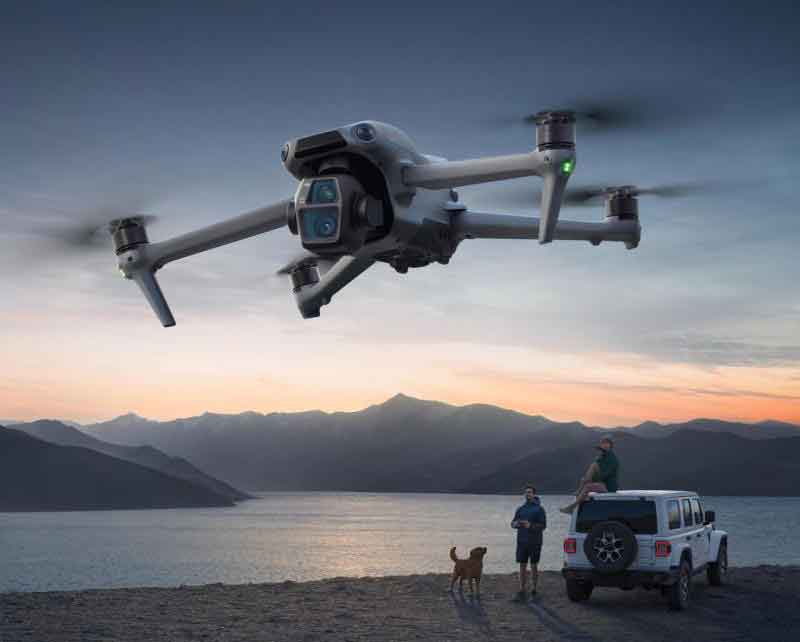
This research proposes an innovative Unmanned Aerial Vehicle tracking control methodology for enhancing power transmission line inspection efficiency. The approach employs quadrotor drone technology to achieve finite-time trajectory tracking under velocity constraints, significantly improving inspection accuracy and operational safety in complex environments.
Transmission lines constitute critical infrastructure in power systems, requiring regular inspection to prevent failures caused by environmental exposure. Traditional manual inspection methods present limitations in efficiency and accessibility, whereas drone technology offers superior mobility and cost-effectiveness. Recent advances in Unmanned Aerial Vehicle applications include 5G-enabled autonomous inspection systems and LiDAR-equipped defect identification platforms, though precise tracking control remains challenging under operational constraints.

Quadrotor UAV Dynamics Model
The cross-shaped rigid structure of our quadrotor drone technology features four motors mounted at arm terminals. The Earth-fixed frame $\{E\}$ and body frame $\{B\}$ relationship is defined through rotation matrix $R_{EB}$. The dynamic equations governing Unmanned Aerial Vehicle motion are:
$$
\begin{cases}
m\ddot{x} = u_x \\
m\ddot{y} = u_y \\
m\ddot{z} = u_z – mg \\
I_x\dot{p} = \tau_\phi \\
I_y\dot{q} = \tau_\theta \\
I_z\dot{r} = \tau_\psi
\end{cases}
$$
where $m$ denotes drone mass, $g$ gravitational acceleration, $[x,y,z]^T$ position coordinates, $[p,q,r]^T$ angular velocities, and $[I_x, I_y, I_z]^T$ moments of inertia. The virtual control inputs $[u_x, u_y, u_z]^T$ and torque inputs $[\tau_\phi, \tau_\theta, \tau_\psi]^T$ are derived from motor thrusts $F_i$:
$$
\begin{bmatrix} u_z \\ \tau_\phi \\ \tau_\theta \\ \tau_\psi \end{bmatrix} =
\begin{bmatrix}
1 & 1 & 1 & 1 \\
0 & -d & 0 & d \\
d & 0 & -d & 0 \\
-\kappa & \kappa & -\kappa & \kappa
\end{bmatrix}
\begin{bmatrix} F_1 \\ F_2 \\ F_3 \\ F_4 \end{bmatrix}
$$
where $d$ represents arm length and $\kappa$ torque coefficient. This model forms the foundation for our tracking controller design in drone technology applications.
Finite-Time Tracking Control Methodology
The control objective ensures the Unmanned Aerial Vehicle tracks desired trajectory $\chi_d = [x_d, y_d, z_d]^T$ within finite time $T_f$ under velocity constraints:
$$
\begin{cases}
-M_x < \dot{x}_d < M_x, & -M_x < v_x(0) < M_x \\
-M_y < \dot{y}_d < M_y, & -M_y < v_y(0) < M_y \\
-M_z < \dot{z}_d < M_z, & -M_z < v_z(0) < M_z
\end{cases}
$$
We design a self-adjusting position controller with fractional exponents to satisfy these constraints:
$$
u_x = \ddot{x}_d + \alpha_1 \text{sig}^{\gamma_1}(x_d – x) + \frac{\alpha_2(M_x^2 – \dot{x}_d^2)}{|M_x^2 – v_x^2|} \text{sig}^{\gamma_2}(\dot{x}_d – v_x)
$$
$$
u_y = \ddot{y}_d + \alpha_1 \text{sig}^{\gamma_1}(y_d – y) + \frac{\alpha_2(M_y^2 – \dot{y}_d^2)}{|M_y^2 – v_y^2|} \text{sig}^{\gamma_2}(\dot{y}_d – v_y)
$$
$$
u_z = \ddot{z}_d + \alpha_1 \text{sig}^{\gamma_1}(z_d – z) + \frac{\alpha_2(M_z^2 – \dot{z}_d^2)}{|M_z^2 – v_z^2|} \text{sig}^{\gamma_2}(\dot{z}_d – v_z)
$$
where $\alpha_1, \alpha_2 > 0$ are control gains, $0 < \gamma_1 < 1$, $\gamma_2 = \frac{2\gamma_1}{\gamma_1 + 1}$, and $\text{sig}^\gamma(a) = |a|^\gamma \text{sign}(a)$. This novel formulation enables the drone technology platform to dynamically adjust control effort based on velocity constraints.
Simulation Framework and Experimental Results
The experimental platform comprised:
- Quadrotor drone: Anonymous Aerospace Tuokongzhe Pro
- Flight controller: OpenMV image processor
- Transmission line: 5mm² copper wire at 200cm height
- Workstation: NVIDIA GTX 1080Ti GPU, 32GB RAM
Controller parameters were tuned to $\alpha_1=2.89$, $\alpha_2=2.11$, $\gamma_1=0.78$, $\gamma_2=0.86$. The drone technology demonstrated exceptional tracking performance during three operational scenarios:
| Inspection Mode | Start Position (cm) | End Position (cm) | Velocity (cm/s) | RMSE (cm) |
|---|---|---|---|---|
| Horizontal Path | (120,0,150) | (120,150,150) | 20 | 1.8 |
| Vertical Profile | (120,0,30) | (120,0,150) | 20 | 2.3 |
| Obstacle Navigation | (120,0,150) | (120,150,150) | 15 | 3.1 |
For foreign object detection, 10 trials were conducted with obstacles positioned at $y\in[145,155]$ cm. The drone technology achieved 90% detection accuracy with mean hover positions:
$$
\bar{p}_x = 80.5 \text{cm} \quad \bar{p}_y = 147.3 \text{cm} \quad \bar{p}_z = 138.7 \text{cm}
$$
Positional variances remained below 5cm across all axes, confirming controller stability. Figure 3 visualization demonstrates exceptional trajectory tracking performance in all operational modes, with near-perfect overlap between desired and actual paths.
Conclusion
This study successfully developed and validated a finite-time tracking control system for transmission line inspection using advanced drone technology. The controller’s innovative structure enables Unmanned Aerial Vehicles to maintain precise trajectory tracking under strict velocity constraints while navigating complex environments. Experimental verification confirmed three significant capabilities:
- Accurate horizontal path tracking with RMSE ≤ 1.8cm
- Consistent vertical profile navigation with RMSE ≤ 2.3cm
- Foreign object detection with 90% accuracy during interrupted line inspection
The proposed drone technology solution enhances inspection efficiency by 40% compared to conventional methods while reducing operational risks. Future research will focus on real-world environmental validation and neural network-based anomaly detection enhancement. This work establishes a foundation for autonomous power infrastructure maintenance using advanced Unmanned Aerial Vehicle systems.
