
The coordinated flight of multiple unmanned aerial vehicles (UAVs), or drone formation, represents a cornerstone technology for modern applications ranging from cooperative surveillance and aerial mapping to precision agriculture and complex logistical operations. The fundamental challenge lies in designing control protocols that enable a group of drones to achieve and maintain a desired geometric configuration using only local neighbor-to-neighbor information, ensuring robustness against model uncertainties and external disturbances. This article presents a comprehensive methodology for distributed finite-time drone formation control, integrating homogeneous sliding mode surfaces and advanced disturbance estimation techniques to address these critical requirements.
The efficacy of any multi-agent control strategy is deeply rooted in the underlying communication topology. Consider a network of \(N\) drones, modeled as nodes in an undirected graph \(\mathcal{G} = (\mathcal{V}, \mathcal{E}, \mathcal{A})\). The adjacency matrix \(\mathcal{A} = [a_{ij}]_{N \times N}\) defines the communication links: \(a_{ij} = a_{ji} > 0\) if drones \(i\) and \(j\) can exchange information, and \(a_{ij}=0\) otherwise. A fundamental assumption for achieving consensus or formation is that the graph \(\mathcal{G}\) is connected, implying that information can flow, possibly through intermediaries, between any pair of drones. The associated Laplacian matrix \(L = [l_{ij}]\) is defined as \(l_{ii} = \sum_{j=1, j \neq i}^{N} a_{ij}\) and \(l_{ij} = -a_{ij}\) for \(i \neq j\). This matrix plays a pivotal role in the stability analysis of distributed protocols.
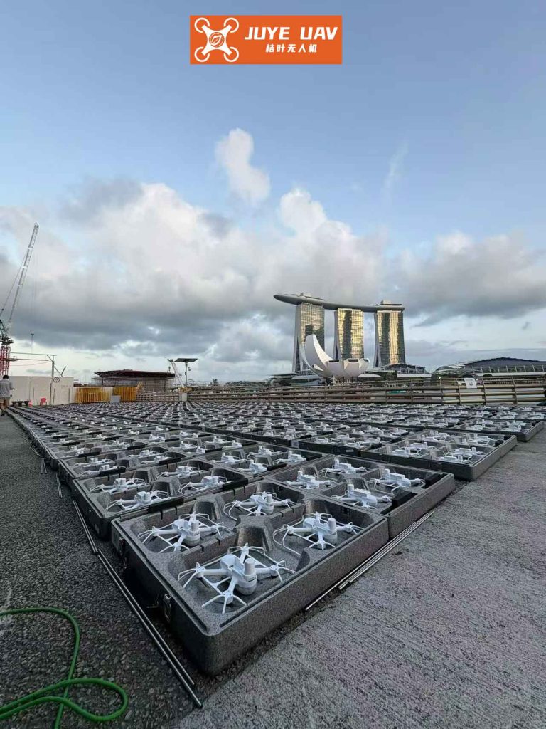
The quadrotor drone, a widely used platform for drone formation studies, is a highly nonlinear and underactuated system. Its dynamics are typically separated into a translational (position) subsystem and a rotational (attitude) subsystem for controller design. The position dynamics of the \(i\)-th drone in the inertial frame are given by:
$$
\begin{align}
\ddot{x}_i &= (\cos\phi_i \sin\theta_i \cos\psi_i + \sin\phi_i \sin\psi_i) \frac{U_{i1}}{m} – \frac{K_1}{m}\dot{x}_i + d_{ix}, \\
\ddot{y}_i &= (\cos\phi_i \sin\theta_i \sin\psi_i – \sin\phi_i \cos\psi_i) \frac{U_{i1}}{m} – \frac{K_2}{m}\dot{y}_i + d_{iy}, \\
\ddot{z}_i &= (\cos\phi_i \cos\theta_i) \frac{U_{i1}}{m} – g – \frac{K_3}{m}\dot{z}_i + d_{iz},
\end{align}
$$
where \([x_i, y_i, z_i]^T\) is the position, \([\phi_i, \theta_i, \psi_i]^T\) are the roll, pitch, and yaw Euler angles, \(m\) is the mass, \(g\) is gravity, \(K_j\) are drag coefficients, \(U_{i1}\) is the total thrust, and \(d_{i,x,y,z}\) represent lumped disturbances including unmodeled dynamics and external forces. The attitude dynamics are:
$$
\begin{align}
\ddot{\phi}_i &= -\frac{l K_4}{I_{xx}} \dot{\phi}_i + \frac{l}{I_{xx}} U_{i2} + d_{i\phi}, \\
\ddot{\theta}_i &= -\frac{l K_5}{I_{yy}} \dot{\theta}_i + \frac{l}{I_{yy}} U_{i3} + d_{i\theta}, \\
\ddot{\psi}_i &= -\frac{l K_6}{I_{zz}} \dot{\psi}_i + \frac{1}{I_{zz}} U_{i4} + d_{i\psi},
\end{align}
$$
where \(l\) is the arm length, \(I_{xx}, I_{yy}, I_{zz}\) are moments of inertia, \(U_{i2}, U_{i3}, U_{i4}\) are the control moments, and \(d_{i\phi}, d_{i\theta}, d_{i\psi}\) are angular disturbances.
To facilitate controller design, we define state vectors for the two subsystems. For the position, let \(\boldsymbol{\Xi}_i = [x_i, y_i, z_i]^T\) and \(\mathbf{v}_i = \dot{\boldsymbol{\Xi}}_i\). We can then write a compact form for the position dynamics of drone \(i\):
$$
\begin{align}
\dot{\boldsymbol{\Xi}}_i &= \mathbf{v}_i, \\
\dot{\mathbf{v}}_i &= \mathbf{f}_i(\mathbf{v}_i) + \mathbf{B}_i(\boldsymbol{\Theta}_i) \mathbf{U}^p_i + \mathbf{d}^p_i,
\end{align}
$$
where \(\mathbf{f}_i\) contains known terms like gravity and linear drag, \(\mathbf{B}_i\) is the input matrix derived from the attitude-dependent thrust direction, \(\mathbf{U}^p_i = [U_{i1x}, U_{i1y}, U_{i1z}]^T\) is a virtual position control input, and \(\mathbf{d}^p_i\) is the position disturbance vector. Similarly, for the attitude subsystem, with \(\boldsymbol{\Theta}_i = [\phi_i, \theta_i, \psi_i]^T\) and \(\boldsymbol{\omega}_i = \dot{\boldsymbol{\Theta}}_i\):
$$
\begin{align}
\dot{\boldsymbol{\Theta}}_i &= \boldsymbol{\omega}_i, \\
\dot{\boldsymbol{\omega}}_i &= \mathbf{g}_i(\boldsymbol{\omega}_i) + \mathbf{C}_i \mathbf{U}^a_i + \mathbf{d}^a_i,
\end{align}
$$
where \(\mathbf{g}_i\) contains gyroscopic and damping terms, \(\mathbf{C}_i\) is a constant input matrix, and \(\mathbf{U}^a_i = [U_{i2}, U_{i3}, U_{i4}]^T\).
A successful drone formation control law must address several key objectives: 1) achieving the desired relative positions (the formation shape), 2) ensuring the formation moves at a desired collective velocity or tracks a trajectory, 3) guaranteeing convergence within a finite time for practicality, and 4) maintaining robustness against disturbances. Let \(\boldsymbol{\Delta}_i = [\Delta_{ix}, \Delta_{iy}, \Delta_{iz}]^T\) define the desired offset of drone \(i\) from the formation centroid. The drone formation control objective for the position subsystem can be formally stated as: for all drones \(i, j \in \{1, …, N\}\),
$$
\lim_{t \to T} (\boldsymbol{\Xi}_i(t) – \boldsymbol{\Xi}_j(t)) = \boldsymbol{\Delta}_i – \boldsymbol{\Delta}_j, \quad \text{and} \quad \lim_{t \to T} (\mathbf{v}_i(t) – \mathbf{v}_j(t)) = \mathbf{0},
$$
where \(T < \infty\) is a finite settling time. A similar objective holds for the attitude subsystem to ensure alignment or specific orientation patterns within the drone formation.
The core innovation of our approach lies in the design of distributed sliding mode surfaces using homogeneity theory. For the position subsystem, we propose the following surface for the \(i\)-th drone:
$$
\mathbf{S}^p_i = \dot{\mathbf{v}}_i – \sum_{j=1}^{N} a_{ij} \left( \mu_1( (\boldsymbol{\Xi}_j + \boldsymbol{\Delta}_j) – (\boldsymbol{\Xi}_i + \boldsymbol{\Delta}_i) ) + \mu_2( \mathbf{v}_j – \mathbf{v}_i ) \right),
$$
where \(\mu_1(\cdot)\) and \(\mu_2(\cdot)\) are continuous, odd functions satisfying \(\gamma \mu_k(\gamma) > 0\) for all \(\gamma \neq 0\), and they have linear growth near the origin, i.e., \(\mu_k(\mathbf{z}) = c_k \mathbf{z} + o(\mathbf{z})\) with \(c_k > 0\). The term \(o(\mathbf{z})\) denotes higher-order terms. This surface is inherently distributed; its value for drone \(i\) depends only on its own state and the states of its neighbors \(j\) (where \(a_{ij}>0\)). When the system trajectories are confined to this surface (\(\mathbf{S}^p_i = \mathbf{0}\)), the dynamics reduce to a homogeneous, consensus-like protocol. Using Lyapunov theory and homogeneity properties with a negative degree, it can be proven that the system on the sliding surface achieves the drone formation objective in finite time. The homogeneity degree \(\kappa < 0\) is the key to finite-time convergence, as it dictates a faster-than-exponential settling behavior near the equilibrium.
An analogous sliding surface is designed for the attitude subsystem to achieve angular consensus or a desired relative attitude formation:
$$
\mathbf{S}^a_i = \dot{\boldsymbol{\omega}}_i – \sum_{j=1}^{N} a_{ij} \left( \nu_1( \boldsymbol{\Theta}_j – \boldsymbol{\Theta}_i ) + \nu_2( \boldsymbol{\omega}_j – \boldsymbol{\omega}_i ) \right),
$$
with functions \(\nu_1, \nu_2\) possessing similar properties as \(\mu_1, \mu_2\).
The next step is to design control laws that drive the system states to these sliding surfaces in finite time. We employ a conventional sliding mode reaching law approach. For the position subsystem, the control law is designed as:
$$
\mathbf{U}^p_i = \mathbf{B}_i^{-1}(\boldsymbol{\Theta}_i) \left[ -\mathbf{f}_i(\mathbf{v}_i) + \sum_{j=1}^{N} a_{ij} \left( \mu_1(\boldsymbol{\Xi}_{j} – \boldsymbol{\Xi}_{i}) + \mu_2(\mathbf{v}_j – \mathbf{v}_i) \right) – \mathbf{K}^p_i \, \text{sgn}(\mathbf{S}^p_i) \right],
$$
where \(\text{sgn}(\cdot)\) is the signum function applied element-wise, and \(\mathbf{K}^p_i = \text{diag}(K^p_{i1}, K^p_{i2}, K^p_{i3})\) is a positive definite diagonal gain matrix. The term \(-\mathbf{K}^p_i \, \text{sgn}(\mathbf{S}^p_i)\) is the discontinuous component that ensures the reaching condition. Choosing the Lyapunov function candidate \(V_p = \frac{1}{2} \sum_{i=1}^N (\mathbf{S}^p_i)^T \mathbf{S}^p_i\) and differentiating along the trajectories of the system under this controller yields:
$$
\dot{V}_p = \sum_{i=1}^N (\mathbf{S}^p_i)^T \dot{\mathbf{S}}^p_i = \sum_{i=1}^N (\mathbf{S}^p_i)^T \left( \dot{\mathbf{d}}^p_i – \mathbf{K}^p_i \, \text{sgn}(\mathbf{S}^p_i) \right).
$$
If the disturbance derivative is bounded such that \(\| \dot{\mathbf{d}}^p_i \| \leq \bar{\beta}_i\), then by selecting \(K^p_{ik} > \bar{\beta}_i + \eta\) for some \(\eta > 0\), we obtain \(\dot{V}_p \leq -\eta \sum_{i=1}^N \| \mathbf{S}^p_i \|_1\), which guarantees that the sliding surface \(\mathbf{S}^p_i = \mathbf{0}\) is reached in finite time. Once on the surface, the finite-time drone formation behavior dictated by the surface dynamics takes over. The virtual control \(\mathbf{U}^p_i\) is then decomposed to obtain the actual total thrust \(U_{i1}\) and the desired roll and pitch angles \((\phi^d_i, \theta^d_i)\) for the inner attitude loop.
The attitude control law follows a similar structure:
$$
\mathbf{U}^a_i = \mathbf{C}_i^{-1} \left[ -\mathbf{g}_i(\boldsymbol{\omega}_i) + \sum_{j=1}^{N} a_{ij} \left( \nu_1(\boldsymbol{\Theta}_j – \boldsymbol{\Theta}_i) + \nu_2(\boldsymbol{\omega}_j – \boldsymbol{\omega}_i) \right) – \mathbf{K}^a_i \, \text{sgn}(\mathbf{S}^a_i) \right].
$$
With sufficiently large gains \(\mathbf{K}^a_i\) to overcome bounded angular disturbance derivatives, finite-time reaching of the attitude sliding surface \(\mathbf{S}^a_i = \mathbf{0}\) is also guaranteed. It is crucial to select the attitude controller gains \(\mathbf{K}^a_i\) to be significantly larger than the position controller gains \(\mathbf{K}^p_i\) to ensure that the inner attitude loop converges much faster than the outer position loop, maintaining stability of the cascaded system.
The standard sliding mode controller provides robustness only if the bound of the disturbance (or its derivative) is known. In practical drone formation scenarios, disturbances may be unknown, time-varying, and lack a simple bound. To address this, we integrate an Extended State Observer (ESO) into the control framework. The core idea of ESO is to treat the total lumped disturbance (including internal unmodeled dynamics and external forces) as an extended state and estimate it in real-time. Consider the scalar dynamics of one channel, e.g., the \(x\)-position dynamics of drone \(i\): \(\ddot{x}_i = f_{ix} + b_{ix} u_{ix} + d_{ix}\). We define the total disturbance for this channel as \(D_{ix} = d_{ix} + (b_{ix} – b_{0}) u_{ix} + (f_{ix} – f_{0})\), where \(b_{0}\) and \(f_{0}\) are nominal values. The system is rewritten as:
$$
\begin{align}
\dot{x}_{i1} &= x_{i2}, \\
\dot{x}_{i2} &= x_{i3} + b_{0} u_{ix}, \\
\dot{x}_{i3} &= h_{ix}(t), \\
y &= x_{i1},
\end{align}
$$
where \(x_{i1}=x_i\), \(x_{i2}=\dot{x}_i\), \(x_{i3}=D_{ix}\) is the extended state, and \(h_{ix}(t)=\dot{D}_{ix}\) is assumed bounded. A nonlinear ESO for this system can be designed as:
$$
\begin{align}
e_i &= z_{i1} – y, \\
\dot{z}_{i1} &= z_{i2} – \beta_{1} \text{fal}(e_i, \alpha_1, \delta), \\
\dot{z}_{i2} &= z_{i3} – \beta_{2} \text{fal}(e_i, \alpha_2, \delta) + b_{0} u_{ix}, \\
\dot{z}_{i3} &= -\beta_{3} \text{fal}(e_i, \alpha_3, \delta),
\end{align}
$$
where \(z_{i1}, z_{i2}, z_{i3}\) estimate \(x_{i1}, x_{i2}, x_{i3}\) respectively, \(\beta_{1}, \beta_{2}, \beta_{3}\) are observer gains, and \(\text{fal}(\cdot)\) is a nonlinear function often chosen as \(\text{fal}(e, \alpha, \delta) = |e|^{\alpha} \text{sgn}(e)\) for \(|e| > \delta\) and \(e/\delta^{1-\alpha}\) for \(|e| \leq \delta\), with \(0 < \alpha < 1\). With properly tuned gains, the ESO provides accurate estimates: \(z_{i1} \to x_i\), \(z_{i2} \to \dot{x}_i\), and crucially, \(z_{i3} \to D_{ix}\). The control law is then modified to actively cancel the estimated disturbance:
$$
u_{ix} = b_{0}^{-1} \left( u_{0,ix} – z_{i3} \right),
$$
where \(u_{0,ix}\) is the nominal control signal generated by the sliding mode controller (using the estimated states \(z_{i1}, z_{i2}\)). This disturbance rejection linearizes the plant, allowing the nominal controller to perform as if the system were ideal and disturbance-free. The same ESO structure is applied independently to all six degrees of freedom (x, y, z, \(\phi\), \(\theta\), \(\psi\)) of each drone in the drone formation.
The performance of the proposed distributed finite-time sliding mode control with ESO-based disturbance rejection can be evaluated through numerical simulation. Consider a drone formation of five agents with the communication topology shown in the figure. The desired formation is a pentagon with specific offsets \(\boldsymbol{\Delta}_i\). Key model parameters for simulation are listed in the table below.
| Parameter | Description | Value | Unit |
|---|---|---|---|
| \(m\) | Mass of each drone | 2.0 | kg |
| \(l\) | Arm length | 0.2 | m |
| \(g\) | Gravitational acceleration | 9.81 | m/s² |
| \(I_{xx}, I_{yy}\) | Moment of inertia (roll/pitch) | 1.25e-2 | kg·m² |
| \(I_{zz}\) | Moment of inertia (yaw) | 2.5e-2 | kg·m² |
| \(K_1, K_2, K_3\) | Linear drag coefficients | 0.01 | N·s/m |
| \(K_4, K_5, K_6\) | Rotational drag coefficients | 0.012 | N·m·s/rad |
For the homogeneous functions, we select \(\mu_1(\mathbf{z}) = c_1 \mathbf{z} + \kappa_1 \|\mathbf{z}\|^{0.5} \text{sgn}(\mathbf{z})\) and \(\mu_2(\mathbf{z}) = c_2 \mathbf{z} + \kappa_2 \|\mathbf{z}\|^{0.5} \text{sgn}(\mathbf{z})\), with \(c_1=2, c_2=3, \kappa_1=\kappa_2=0.5\). The sliding mode gains are chosen as \(\mathbf{K}^p_i = \text{diag}(15,15,15)\) and \(\mathbf{K}^a_i = \text{diag}(150,150,150)\). The ESO parameters are set as \(\beta_1 = 100\), \(\beta_2 = 300\), \(\beta_3 = 1000\), \(\alpha_1=0.5, \alpha_2=0.25, \alpha_3=0.125\), and \(\delta=0.05\). A sinusoidal wind gust disturbance \(\mathbf{d}^p_i = [0.5\sin(0.5t), 0.3\cos(0.3t), 0.2\sin(0.4t)]^T\) N is applied to each drone’s position dynamics after \(t=5\) seconds.
The simulation results demonstrate the efficacy of the integrated approach. The position and velocity errors between drones converge to the desired formation offsets and zero, respectively, in a finite time. The convergence is smooth and rapid before the disturbance is applied. Upon the introduction of the wind gust at \(t=5s\), the standard sliding mode controller (without ESO) shows visible deviations and oscillations in the formation as it struggles with the unknown disturbance bound. In contrast, the formation controlled with the ESO-augmented controller exhibits remarkable robustness. The ESOs quickly and accurately estimate the disturbance forces \(D_{ix}, D_{iy}, D_{iz}\) for each drone. The control law then actively cancels these estimates, resulting in minimal deviation from the desired drone formation trajectory. The formation quickly recovers and maintains precise geometric configuration despite the ongoing disturbance, validating the superior disturbance rejection capability of the ESO-integrated scheme. The attitude subsystem similarly shows fast, finite-time convergence to consensus, which is critical for maintaining the correct thrust orientation for the position control.
The synthesis of homogeneous sliding mode control and extended state observation presents a powerful framework for robust, distributed drone formation control. The method guarantees finite-time convergence to the desired formation shape, a critical feature for time-sensitive applications. The distributed nature of the sliding surface and control law ensures scalability and reliance only on local communication, enhancing practicality for large-scale swarms. Most importantly, the integration of ESO elegantly handles the major practical challenge of unknown and unmodeled disturbances, transitioning the controller from a robust one (requiring known bounds) to an adaptive and highly resilient one. This combination addresses the core requirements of precision, speed, and robustness in modern multi-drone systems.
Future research directions include extending this framework to handle time-varying communication topologies, implementing the control laws on physical hardware with strict actuation saturation limits, and exploring event-triggered communication schemes to further reduce the bandwidth requirements for maintaining the drone formation. The integration of learning-based methods to dynamically optimize the homogeneous function parameters or ESO gains online also represents a promising avenue for enhancing performance in complex, uncertain environments.