The evolution of aerial systems has been persistently driven by the need for greater flexibility, endurance, and mission capability. A significant milestone in this journey is the emergence and maturation of the Vertical Takeoff and Landing Fixed Wing Unmanned Aerial Vehicle (VTOL UAV). This class of aircraft uniquely combines the runway independence and hover capability of helicopters with the efficient, high-speed forward flight of traditional airplanes. The strategic value of such a platform is immense, enabling operations from confined spaces, ships at sea, or unprepared fields while retaining the ability to cover large distances quickly and efficiently. We have witnessed a global surge in research and development focused on VTOL UAV technologies, fueled by both military programs seeking next-generation tactical assets and commercial applications in logistics, surveillance, and mapping. This article delves into the current state of VTOL UAV technology, analyzes the fundamental characteristics and challenges of prevailing configurations, and outlines the key trends shaping their future evolution.
The core appeal of the VTOL UAV lies in its multi-modal flight envelope. During takeoff and landing, it operates like a helicopter or multirotor, using directed thrust to lift vertically. After achieving a safe altitude, it transitions into forward flight, where the fixed wing generates lift much more efficiently than rotating blades, allowing for higher cruise speeds and dramatically improved range and endurance. This duality, however, introduces significant design complexities, as the aircraft must excel in two radically different flight regimes. The fundamental challenge can be expressed through a simple power requirement comparison. The thrust-to-weight ratio for hover must be greater than 1:
$$ T_{hover} > W $$
where $T_{hover}$ is the total thrust generated in hover and $W$ is the vehicle weight. In contrast, for level cruise flight in a fixed-wing configuration, the required thrust is only a fraction of the weight, balanced by aerodynamic drag:
$$ T_{cruise} \approx D = \frac{1}{2} \rho V^2 S C_D $$
where $D$ is drag, $\rho$ is air density, $V$ is velocity, $S$ is wing area, and $C_D$ is the drag coefficient. For a typical efficient fixed-wing aircraft, the ratio $T_{cruise}/W$ can be as low as 0.1 to 0.3. This creates a fundamental mismatch: the propulsion system must be sized for the high-power hover condition but operates at a small fraction of that capacity during cruise, leading to potential inefficiency. This core tension drives the diversity of configurations we see today, each attempting to solve this problem in a different way.
Current Landscape of VTOL UAV Configurations
Extensive research and development efforts worldwide have converged on several dominant architectural paradigms for VTOL UAV. These can be broadly categorized based on how they manage the generation and vectoring of lift/thrust between vertical and forward flight modes.
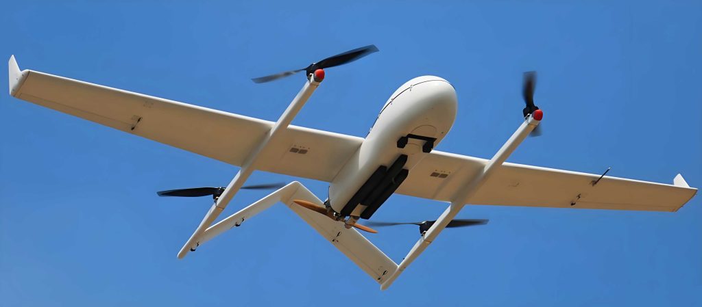
1. Lift-Plus-Cruise (L+C) Configuration
This is perhaps the most conceptually straightforward approach to designing a VTOL UAV. The L+C configuration features two largely independent sets of propulsors: one dedicated to providing vertical lift (typically multi-rotors or lift propellers) and another dedicated to providing forward thrust in cruise (a conventional tractor or pusher propeller or a jet engine). During vertical takeoff, hover, and landing, only the lift system is active. For transition and cruise, the lift system is shut down (and sometimes folded or stowed to reduce drag), and the forward propulsion system takes over. This design benefits from simplicity and the ability to optimize each propulsor for its specific single-point design condition.
However, the major drawback is mass inefficiency. The entire lift system becomes dead weight during cruise, and vice-versa. Furthermore, during the transition phase, the downwash from the lift rotors can cause significant and complex aerodynamic interference with the wings and control surfaces, affecting stability and control. A notable sub-category is the stopped-rotor or rotating-wing concept, where the main lifting rotor can be stopped and locked to act as a fixed wing during forward flight. While elegant in theory, this imposes severe compromises on airfoil design (requiring symmetric profiles) and introduces challenging aeroelastic and control interactions due to rotor wake impingement on the tail and fuselage during hover.
2. Tail-Sitter Configuration
The tail-sitter VTOL UAV adopts an elegant, minimalist approach to mode transition. The entire airframe, with its propulsion system fixed in relation to the body, rotates 90 degrees between flight phases. It takes off and lands sitting on its tail, with its longitudinal axis vertical. Once airborne, it pitches forward to transition into conventional horizontal flight. This design eliminates the need for complex tilting mechanisms for the motors or wings, leading to a potentially simpler and more robust mechanical structure.
The primary challenges for the tail-sitter VTOL UAV are in flight dynamics and control. During vertical flight, it has a high center of gravity, making it susceptible to ground winds and tipping. The transition corridor is critical and demanding, requiring precise control of pitch attitude and thrust magnitude as aerodynamic forces on the wings build up. The control authority and thrust vectoring requirements during the low-speed, high-angle-of-attack transition can be extreme. The control moment during transition, $M_{transition}$, must overcome aerodynamic damping and inertial effects:
$$ M_{transition} = T \cdot d + M_{aero} \approx I_{yy} \cdot \dot{q} $$
where $T$ is thrust, $d$ is the moment arm from the center of gravity, $M_{aero}$ is the aerodynamic pitching moment, $I_{yy}$ is the pitch moment of inertia, and $\dot{q}$ is the pitch acceleration. Generating sufficient $T \cdot d$ with a compact airframe is a key design challenge for tail-sitter VTOL UAV platforms.
3. Tilt-Propulsor Configuration
This is the most prevalent category for high-performance VTOL UAV systems, where the propulsors themselves rotate to vector their thrust. It can be further divided into subtypes.
Tilt-Rotor: This configuration, inspired by manned aircraft like the V-22 Osprey, features large-diameter rotors mounted on rotating nacelles at the wingtips. It offers excellent hover efficiency (comparable to helicopters) and high cruise speed. The major technical hurdles involve severe rotor-wing aerodynamic interference in hover (download on the wing), complex aeroelastic coupling (whirl flutter), and the need for a heavy, reliable cross-shafting transmission system to allow one engine to drive both rotors in case of failure. The downwash velocity $v_i$ in hover induces a download force $D_{wing}$ on the wing:
$$ D_{wing} \propto \frac{1}{2} \rho v_i^2 S_{wing} $$
This download can account for a significant penalty (e.g., 10-15%) on the total thrust required for a VTOL UAV of this type.
Tilt-Duct: Similar to tilt-rotor but the propeller is enclosed within a duct. The duct offers advantages like increased static thrust (by reducing tip losses), improved safety, and lower noise. However, ducts add weight and, in forward flight, can create substantial drag, limiting the maximum speed and efficiency of the VTOL UAV. The thrust augmentation ratio of a ducted fan in hover can be modeled as:
$$ \frac{T_{ducted}}{T_{free}} \approx 1 + \frac{C_T}{\sigma} $$
where $C_T$ is the thrust coefficient and $\sigma$ is the duct solidity factor, but this benefit must be traded against the duct’s cruise drag penalty $D_{duct}$.
Tilt-Wing / Distributed Tilt-Propulsor: A more integrated approach where multiple smaller propulsors are distributed along a wing section that tilts as a whole. This is closely associated with Distributed Electric Propulsion (DEP). This configuration allows for powerful wing-blown lift augmentation effects, potentially reducing wing area and weight. The many small propulsors offer redundancy and fine-grained control authority. The challenge lies in managing the complex structure and actuation of the tilting wing segment and the integration of numerous electric motors, inverters, and controllers. The power-off drag of multiple small nacelles can also be an issue.
The following table summarizes the key characteristics of these primary VTOL UAV configurations:
| Configuration | Key Advantage | Primary Challenge | Typical Use Case |
|---|---|---|---|
| Lift-Plus-Cruise (L+C) | Simplicity, independent optimization of lift/cruise systems | High dead weight, aerodynamic interference during transition | Medium endurance, tactical ISR |
| Tail-Sitter | Mechanical simplicity, no complex tilting mechanisms | Difficult low-speed control, sensitive to crosswinds, complex transition | Ship-based operations, long-endurance missions |
| Tilt-Rotor | High hover efficiency & high cruise speed | Complex transmission, rotor-wing interference, aeroelasticity | Long-range, high-speed tactical missions |
| Tilt-Duct | Good hover thrust, safer, quieter | Duct drag in cruise, weight penalty | Urban air mobility, operations near people |
| Tilt-Wing / DEP | High redundancy, control authority, potential for lift augmentation | Complex tilting structure, electrical system integration & thermal management | Next-generation high-performance, agile platforms |
Technical Challenges and Performance Analysis
Beyond configuration-specific issues, all VTOL UAV designs grapple with a set of common, profound technical challenges that stem from their dual-mode nature.
Aerodynamic Interference: This is a pervasive issue. In hover, the downwash from lift propulsors impinges on fuselages, wings, and tails, creating unsteady loads, reducing propulsive efficiency, and complicating the flow field for control surfaces. In forward flight, the wakes from propellers or rotors (if still spinning) interact with wing aerodynamics, potentially causing vibration, unsteady loading, and modified stall characteristics. Computational Fluid Dynamics (CFD) and advanced wind tunnel testing are essential to understand and mitigate these effects, but they remain a significant source of design uncertainty for VTOL UAV engineers.
Flight Dynamics and Control: The flight dynamics of a VTOL UAV are highly nonlinear and configuration-dependent, especially during the transition phase. The aircraft evolves from a thrust-vectored multirotor-like dynamics model to a fixed-wing aircraft model. Control allocation—deciding how to use available control effectors like propulsor thrust, tilt angle, and aerodynamic surfaces—becomes a complex optimization problem. The system must be stable and controllable across the entire flight envelope, including failure cases. This requires robust adaptive control laws and often a significant amount of control power, which can impact sizing. The equations of motion switch regime; for example, pitch control in hover may come from differential thrust $\Delta T$:
$$ \Delta T \cdot l_{arm} = I_{yy} \cdot \ddot{\theta} $$
while in cruise, it comes from elevator deflection $\delta_e$:
$$ q S \bar{c} C_{m_{\delta_e}} \delta_e = I_{yy} \cdot \ddot{\theta} $$
Managing this handover and blending is a core control challenge for any VTOL UAV project.
Propulsion and Powerplant Design: As highlighted by the thrust mismatch problem, the propulsion system is a key driver of VTOL UAV performance. For combustion-engine systems, this means an engine that is oversized for cruise, often operating at off-design, inefficient points. For electric VTOL UAV systems, this translates into massive battery packs needed to supply peak hover power, which are then mostly dead weight in cruise, severely limiting endurance. The required hover power $P_{hover}$ is much greater than cruise power $P_{cruise}$:
$$ P_{hover} \approx \frac{T^{3/2}}{\sqrt{2 \rho A}} \quad \text{(Momentum Theory)} $$
$$ P_{cruise} = T_{cruise} \cdot V = D \cdot V $$
$$ \text{Typically, } \frac{P_{hover}}{P_{cruise}} \gg 1 $$
Hybrid-electric systems, where a gas turbine or engine generates electricity to drive distributed fans and charges a battery buffer for peak power, are seen as a promising solution for larger VTOL UAV systems to break the endurance barrier.
Structural and Weight Considerations: VTOL UAV structures must be strong enough to handle high maneuver loads in forward flight and the concentrated loads from lift propulsors in hover, yet light enough to allow for useful payload and endurance. Tilting mechanisms add weight, complexity, and potential failure points. The structural weight fraction is a critical metric, and advanced composites and integrated design are essential.
| Technical Challenge Area | Impact on VTOL UAV Design | Mitigation Strategies |
|---|---|---|
| Aerodynamic Interference | Reduced efficiency, unsteady loads, control complexity | High-fidelity CFD/CSD analysis, wind tunnel testing, geometric shaping, active flow control |
| Flight Control & Transition | Risk of instability or loss of control during critical flight phases | Nonlinear adaptive control laws, extensive control simulation, hardware-in-the-loop testing, control redundancy |
| Propulsion-Power Mismatch | Low cruise efficiency, short electric endurance, heavy powerplants | Hybrid-electric systems, DEP with partial propulsor shutdown in cruise, advanced battery tech (solid-state) |
| Weight & Structures | Reduces payload capacity, endurance, and performance | Advanced composite materials, additive manufacturing, integrated structure-propulsion design |
Future Trends and Evolutionary Pathways
The trajectory of VTOL UAV development is being shaped by the relentless pursuit of greater speed, range, payload, and reliability. Several dominant trends are now clear.
Tilt-Rotor and Tail-Sitter as Current Mainstream Platforms: For near-term military and high-end commercial applications requiring proven performance, tilt-rotor and tail-sitter configurations are leading the way. Tilt-rotor VTOL UAV technology benefits from decades of manned aircraft investment, offering a compelling balance of speed and hover capability. Tail-sitter VTOL UAV designs are particularly attractive for naval applications due to their compact footprint and mechanical simplicity for shipboard operations. The immediate research focus for these configurations is on incremental but critical improvements: advanced rotor designs for better efficiency and noise reduction, refined flight control systems for safer autonomous operations, and more robust and lighter transmission/structural systems.
The Rise of Distributed Electric Propulsion (DEP): This is arguably the most transformative trend in VTOL UAV design. DEP involves using multiple small electric motors and propulsors distributed across the airframe. When applied to VTOL UAV, DEP offers revolutionary advantages:
- Enhanced Aerodynamic Efficiency: By placing propellers upstream of wing surfaces, the propeller slipstream can be used to re-energize the boundary layer, delaying flow separation and allowing wings to operate at higher lift coefficients. This “blown wing” or “boundary layer ingestion” effect can enable smaller, lighter wings. The effective lift coefficient can be enhanced: $C_{L_{eff}} \approx C_L + \Delta C_{L_{blown}}$.
- Unprecedented Control Authority and Redundancy: Each DEP unit can be controlled independently in speed and, if vectored, in thrust direction. This provides immense control power for stabilization, maneuvering, and handling failure conditions. A DEP-based VTOL UAV can lose several propulsors and retain controllability.
- Propulsor-As-Structure Integration: Small electric motors can be deeply integrated into the airframe, potentially improving structural efficiency and reducing nacelle drag.
The challenge for DEP VTOL UAV lies in the maturity of the electrical systems—specifically, achieving the necessary power density (kW/kg) in motors, inverters, and thermal management systems, and the energy density (Wh/kg) in batteries or the efficiency of hybrid-electric generators.
Exploration of Novel Configurations and Principles: To fundamentally break the hover-cruise power mismatch, researchers are revisiting and advancing novel aerodynamic principles that reduce the pure thrust requirement for hover. These concepts aim to generate lift more efficiently during VTOL phases by leveraging aerodynamic surfaces even at low speeds. Promising avenues include:
- Advanced Circulation Control: Using blown air over specially shaped Coanda surfaces (e.g., rounded trailing edges) to dramatically increase lift coefficients on wings or tails at very low speeds, reducing the required propulsive thrust.
- Propulsive-Wing Concepts: Deep integration of propulsion into the wing, such as the “Fan-Wing” or embedded cross-flow fans, which generate lift directly from the propulsion system’s action on the wing, not just from thrust vectoring.
- Extreme STOL with Thrust Vectoring: Focusing on very short takeoff and landing (STOL) with high-lift devices and modest thrust vectoring, accepting a short roll rather than pure vertical lift, to relax power requirements and simplify design, creating a highly capable VTOL UAV variant.
The exploration of these new concepts for VTOL UAV is vital for achieving the next leap in performance.
| Trend | Driver | Key Enabling Technologies | Expected Impact on VTOL UAV |
|---|---|---|---|
| Maturation of Tilt-Rotor/Tail-Sitter | Immediate operational needs, reliability | Advanced flight controls, composites, condition-based maintenance | Fielding of robust, long-range tactical VTOL UAV systems |
| Advent of DEP-Hybrid Systems | Demand for higher efficiency, agility, and redundancy | High-power-density electric motors, advanced power management, hybrid-electric gen-sets | Next-gen high-performance VTOL UAV with unparalleled control and potential for greater efficiency |
| Research into Novel Lift Concepts | Fundamental physics of hover power penalty | Active flow control, advanced CFD/MDO, smart materials | Potential for revolutionary VTOL UAV designs with order-of-magnitude better lift-to-power ratios in hover |
In conclusion, the field of Vertical Takeoff and Landing Fixed Wing Unmanned Aerial Vehicles is in a state of dynamic and rapid evolution. The VTOL UAV has proven its conceptual value, and current efforts are focused on translating that value into practical, high-performance systems. While tilt-rotor and tail-sitter configurations represent the current state of the art for demanding applications, the future is being shaped by the paradigm-shifting potential of Distributed Electric Propulsion. The integration of DEP with hybrid power systems and intelligent, adaptive control promises to unlock new levels of efficiency, agility, and mission capability for VTOL UAV platforms. Simultaneously, the continued exploration of novel aerodynamic principles is essential to overcome the fundamental energy constraints of vertical flight. As these technologies mature, we can anticipate the emergence of a new generation of VTOL UAV that will redefine the possibilities of unmanned aerial systems, performing roles from long-endurance maritime surveillance and tactical logistics to urban air mobility, with unprecedented flexibility and efficiency. The journey of the VTOL UAV is accelerating, promising to be a cornerstone of both future defense and civilian aviation ecosystems.