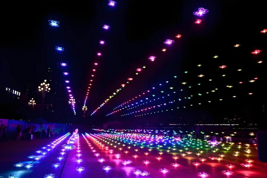
As a researcher in the field of unmanned aerial vehicle (UAV) technology, I have dedicated significant effort to understanding and mitigating the risks associated with large-scale drone shows. These performances, which involve coordinated fleets of drones creating intricate aerial displays, have gained popularity in events ranging from cultural celebrations to corporate presentations. However, the complexity of these systems introduces numerous safety challenges that must be addressed through rigorous design principles. In this article, I will explore the safety system architecture for drone shows, focusing on risk assessment methodologies, control measures, and the integration of geographic and severity considerations. The goal is to provide a comprehensive framework that ensures the reliability and safety of drone shows, thereby supporting their standardized application in various environments.
Drone shows rely on precise coordination between multiple UAVs, often operating in close formation to produce visual patterns. The safety of these performances hinges on a multi-layered system that accounts for potential failures in hardware, software, communication, and human operations. From my perspective, a proactive approach to design is essential, as it allows for the anticipation of incidents before they escalate into accidents. This involves defining clear geographic zones, establishing severity levels for potential events, and implementing a risk analysis matrix to evaluate and control hazards. Throughout this discussion, I will emphasize the importance of incorporating these elements into the initial design phase of a drone show, as retrofitting safety measures can be less effective and more costly.
One of the foundational aspects of drone show safety is the system architecture, which I categorize into two primary components: the Investment Protection System (IPS) and the Human and Environmental Protection System (HPS). The IPS includes two layers: L1, which enables autonomous fault detection and emergency commands, and L2, which provides manual override capabilities for the flight commander to halt drones individually or collectively. This system is designed to contain drones within designated areas, such as the flight zone and its buffers, using a combination of radio and wireless networks. For instance, if a drone enters the IPS buffer zone, the system triggers an engine shutdown to prevent further deviation. The HPS, comprising layer L3, serves as a final safeguard, involving a “kill switch” that, when activated, cuts power to all drones, causing them to descend immediately. This is crucial for protecting humans and the environment in rare cases where the IPS fails. In my experience, the integration of these systems requires careful calibration to balance responsiveness with stability, ensuring that false alarms do not disrupt the drone show unnecessarily.
To delineate the operational boundaries of a drone show, I define several geographic zones, each with specific safety protocols. The flight zone is the core area where drones are permitted to operate, bounded by horizontal and vertical limits. Surrounding this is the IPS buffer zone, where drones are not allowed but may inadvertently enter; detection here triggers automatic engine shutdown. Beyond that lies the public buffer zone, monitored by kill switch operators who can initiate a full shutdown if a drone breaches this area. Finally, the public zone is strictly off-limits, enforced through manual oversight. The dimensions of these zones depend on factors like drone performance and environmental conditions, and they must be validated through testing. For example, the minimum distance between zones can be calculated using the formula for safe operational margins: $$d_{min} = v_{max} \times t_{response} + \epsilon$$ where \(d_{min}\) is the minimum distance, \(v_{max}\) is the maximum drone velocity, \(t_{response}\) is the system response time, and \(\epsilon\) is a safety margin accounting for uncertainties. This zoning approach is critical for containing incidents within the drone show area and minimizing external risks.
In assessing the severity of potential events during a drone show, I adopt a classification system based on EU regulations, which distinguishes between incidents and accidents. Incidents refer to non-accidental events that could affect operational safety, such as drones behaving erratically but without causing harm. Accidents involve fatal injuries, severe damage, or complete loss of the drone. I further categorize severity into three levels: low (e.g., all drones operating normally), medium (e.g., partial flight failures requiring emergency landings), and high (e.g., drones causing injuries or leaving controlled zones). For instance, a drone losing propulsion and landing in a buffer zone might be a medium-severity incident, whereas one colliding with a person would be high-severity. This classification helps prioritize risk control measures in the design of a drone show, ensuring that resources are allocated to mitigate the most critical threats.
Risk analysis for drone shows involves evaluating the likelihood and severity of various failure modes. I use a matrix approach to systematically assess these risks, considering factors such as hardware components, communication systems, software vulnerabilities, flight trajectories, and ground facilities. The likelihood of a fault is rated on a scale from A (extremely improbable) to C (occasional), with corresponding probabilities, as shown in Table 1. This table summarizes the probability levels used in the risk analysis for a drone show, providing a basis for quantifying potential failures.
| Probability Level | Description | Probability |
|---|---|---|
| A | Extremely Improbable | ≤ 1/10,000 |
| B | Improbable | ≤ 1/1,000 |
| C | Occasional | ≤ 1/100 |
Building on this, I develop a risk analysis matrix that maps specific faults to their likelihood, severity, causes, direct effects, higher-level impacts, and control measures. For example, a propeller detachment during a drone show might be rated as improbable (B) with medium severity (I2u), leading to unstable flight and potential emergency landing. The root cause could be physical damage or wear, and control measures include pre-show checks and technical testing. Similarly, software glitches in the ground station could cause communication failures, requiring redundant systems and continuous monitoring. This matrix, presented in Table 2, covers a wide range of scenarios, emphasizing the need for holistic design in drone show safety. Each entry is derived from empirical data and simulations, ensuring that the analysis reflects real-world conditions.
| Fault ID | Fault Description | Likelihood | Severity | Potential Causes | Direct Effect | Higher-Level Impact | Risk Control Measures |
|---|---|---|---|---|---|---|---|
| 1 | Propeller Loosening | B | I2u | Physical damage, vibration | Tracking errors | Unstable flight, emergency landing | Pre-show rehearsals, standard procedures, technical tests |
| 2 | Propeller Detachment | B | I2u | Wear, collision damage | Flight instability | Free fall, potential impact | Regular inspections, testing protocols |
| 3 | Engine Loosening | B | I2u | Vibration, transport damage | Flight instability | Emergency landing | Maintenance checks, operational guidelines |
| 4 | Engine Detachment | B | I2u | Structural failure, damage | Loss of propulsion | Crash, debris hazard | Redundant systems, safety margins |
| 5 | Engine Vibration | B | I2 | Imbalance, wear | Increased tracking error | Performance degradation | Vibration analysis, balancing |
| 6 | Motor Failure | B | I2u | Electrical fault, overheating | Partial or total power loss | Controlled or uncontrolled descent | Thermal management, fault-tolerant design |
| 7 | Propeller Guard Detachment | B | I2 | Impact, poor installation | Reduced safety barrier | Increased injury risk | Secure fastening, impact tests |
| 8 | Engine Controller Fault | B | I2u | Electronic failure, damage | Control signal loss | Erratic behavior, emergency landing | Redundant controllers, testing |
| 9 | Gyroscope Failure | B | I2u | Sensor damage, electronic issues | Unreliable attitude data | Unstable flight, possible crash | Sensor redundancy, calibration |
| 10 | Accelerometer Failure | B | I2u | Physical shock, fault | Inaccurate acceleration data | Trajectory deviations | Multi-sensor fusion, checks |
| 11 | Magnetometer Failure | B | I2u | Magnetic interference, damage | Compass errors | Navigation issues | Shielding, alternative navigation |
| 12 | Barometer Failure | B | I2 | Pressure sensor fault | Altitude errors | Collision risks | Redundant altimeters, validation |
| 13 | Insufficient Battery | C | I2 | Poor charging, high load | Sudden shutdown | Emergency landing | Battery management, pre-show checks |
| 14 | Empty Battery | B | A0 | Complete discharge | Power loss | Crash | Monitoring systems, reserves |
| 15 | Programmable Logic Crash | A | A0 | Software bug, overload | Engine stop | Drone fall | Software validation, failsafes |
| 16 | Onboard Computer Crash | B | I3u-I4 | Hardware failure, software error | Loss of communication | Controlled emergency landing | Robust computing, heartbeat signals |
| 17 | Communication Link Loss | B | I2 | Antenna damage, interference | No direct effect initially | Connection failure, landing | Redundant links, signal monitoring |
| 18 | Missing Master Pulse | B | I2 | Ground station issue, range exceed | No direct effect | Link loss, emergency procedures | Backup systems, range limits |
| 19 | Heartbeat Signal Loss | B | A0 | Transmitter failure, power loss | Emergency stop triggered | Engine shutdown, fall | Heartbeat monitoring, backups |
| 20 | Software Segmentation Fault | B | I2 | Code error, memory issue | No communication to low-level | Controlled landing | Code reviews, testing |
| 21 | Algorithm Error | B | I2u | Low-level software bug | Flight instability | Large tracking errors | Algorithm validation, simulations |
| 22 | Trajectory Command Error | B | A0 or I5 | Software漏洞, incorrect data | Unexpected maneuvers | Engine shutdown, crash | Trajectory verification, limits |
| 23 | Collision with Static Object | A | I2 or I5 | Wind gusts, model error | Hardware damage | Increased severity | Environmental modeling, avoidance |
| 24 | Collision with Other Drones | B | I2 | Bird strikes, emergency descent | Potential hardware damage | Secondary failures | Collision avoidance systems |
| 25 | GPS Signal Loss | B | A0 | Signal blockage, failure | No direct effect | Emergency shutdown | Multi-GNSS, backup navigation |
| 26 | Leaving Flight Zone | B | A0 | Hardware fault, wind, software error | Landing in buffer | Kill switch activation | Geofencing, monitoring |
| 27 | Leaving IPS Buffer | A | A1 | Initial velocity, fault | No direct effect | Kill switch use | Operator training, visual checks |
| 28 | Leaving Public Buffer | A | A2 | System failure | No direct effect | Full shutdown | Redundant controls, procedures |
| 29 | Large Tracking Error | C | I2u | Model inaccuracies, wind | No direct effect | Emergency landing | Error compensation, adaptive control |
| 30 | Ground Station Power Loss | A | I2 | Power outage, generator failure | No master pulse | Connection loss, landing | Backup power, UPS systems |
| 31 | Ground Station Computer Crash | B | I2 | Hardware fault, software error | Loss of control interface | Emergency procedures | Redundant computers, recovery |
| 32 | User Interface Failure | B | I2 | Software crash | Inability to command | Link failure, landing | Interface testing, fallbacks |
| 33 | IPS Hardware Button Fault | A | N1-N2 | Electronic failure | Degraded manual control | Reduced safety margin | Regular maintenance, testing |
| 34 | Time Code Signal Loss | B | N1-N2 | Cable damage, system fault | No direct effect | Loss of synchronization | Redundant time sources, checks |
The risk analysis matrix highlights the interdependence of various factors in a drone show. For instance, the probability of a fault can be modeled using statistical distributions, such as the exponential distribution for time between failures: $$P(t) = 1 – e^{-\lambda t}$$ where \(P(t)\) is the probability of failure by time \(t\), and \(\lambda\) is the failure rate derived from historical data. By applying this to each component, I can estimate the overall reliability of the drone show system. Additionally, the severity of an event can be quantified using a risk score \(R\), calculated as the product of likelihood \(L\) and severity \(S\): $$R = L \times S$$ where \(L\) is normalized to a numerical scale (e.g., A=0.0001, B=0.001, C=0.01), and \(S\) is assigned values based on the severity level (e.g., low=1, medium=2, high=3). This allows for prioritization; for example, faults with \(R > 0.002\) might require immediate design changes. In practice, I have found that this quantitative approach, combined with qualitative insights from experienced operators, enhances the safety of drone shows significantly.
Communication systems are particularly vulnerable in drone shows, as they rely on wireless networks and radio links that can be affected by interference, range limitations, or hardware failures. To mitigate these risks, I recommend implementing redundant communication channels, such as dual-band Wi-Fi and cellular backups, along with encryption to prevent unauthorized access. The heartbeat signal, which continuously verifies the connection between the ground station and drones, is critical; if lost, it triggers an emergency shutdown. The probability of communication failure can be reduced by using diversity techniques, such as multiple antennas, and by conducting pre-show site surveys to identify potential sources of interference. Moreover, software vulnerabilities must be addressed through rigorous testing, including unit tests, integration tests, and real-world simulations. For example, I often use formal methods to verify critical software components, ensuring that they adhere to specified safety properties. This is especially important for autonomous functions in a drone show, where a single bug could lead to cascading failures.
Flight trajectory design is another key aspect of drone show safety. I employ path planning algorithms that minimize the risk of collisions and ensure that drones maintain safe distances from each other and obstacles. These algorithms often incorporate constraints based on the geographic zones, such as avoiding buffer zones unless in an emergency. The trajectory can be optimized using cost functions that account for factors like energy consumption and risk exposure: $$J = \int_{0}^{T} \left( \alpha \cdot \text{risk}(t) + \beta \cdot \text{energy}(t) \right) dt$$ where \(J\) is the total cost, \(\alpha\) and \(\beta\) are weighting factors, and the integral is over the flight duration \(T\). By simulating these trajectories under various conditions, I can identify potential hotspots where failures are more likely and adjust the design accordingly. Additionally, emergency procedures, such as controlled landings or return-to-home functions, are integrated into the trajectory planning to handle faults gracefully. In my work, I have observed that well-designed trajectories not only enhance the visual appeal of a drone show but also its resilience to disruptions.
Ground facilities, including the ground station and kill switch operators, play a vital role in drone show safety. The ground station must be robust, with redundant power supplies and fault-tolerant computing systems. Operators should undergo thorough training to respond quickly to incidents, and their performance can be evaluated using metrics like response time and decision accuracy. For example, the expected response time for activating the kill switch can be modeled as: $$t_{response} = t_{detect} + t_{decide} + t_{act}$$ where \(t_{detect}\) is the time to detect a breach, \(t_{decide}\) is the decision time, and \(t_{act}\) is the time to physically activate the switch. By minimizing these components through automation and training, the overall safety of the drone show is improved. Furthermore, regular maintenance and pre-show checks are essential to prevent faults in ground equipment, such as time code systems that synchronize drone movements.
In conclusion, the safety of drone shows depends on a comprehensive design approach that integrates geographic zoning, severity classification, and risk analysis. From my perspective, this involves not only technical solutions but also human factors, such as operator training and public awareness. As drone technology evolves, safety systems must adapt to new challenges, such as larger fleets or more complex performances. By applying the principles outlined here—including the use of matrices, formulas, and structured protocols—I believe that drone shows can achieve high levels of reliability and safety. This will enable their continued growth as a form of entertainment, while protecting people and the environment. Ultimately, the goal is to make drone shows not only spectacular but also inherently safe through thoughtful design and continuous improvement.