
The promulgation of the national mandatory standard GB 42590-2023, “Safety Requirements for Civil Unmanned Aircraft Systems,” has established specific performance criteria for UAV drones, including metrics like hovering accuracy and trajectory-keeping precision. In current testing methodologies, the prevalent technique involves loading a Real-Time Kinematic (RTK) capable device onto the UAV drones to act as the measurement payload. However, commercially available RTK rover modules typically weigh around 700 grams. This mass is excessive when testing micro-class UAV drones, which often have a maximum takeoff weight (MTOW) of approximately 500 grams. Loading such a heavy device severely impacts the flight dynamics and payload capacity of the UAV drones, rendering standard compliance testing impossible. This creates a pressing need for a novel, ultra-lightweight RTK system specifically designed for the performance evaluation of light and micro UAV drones.
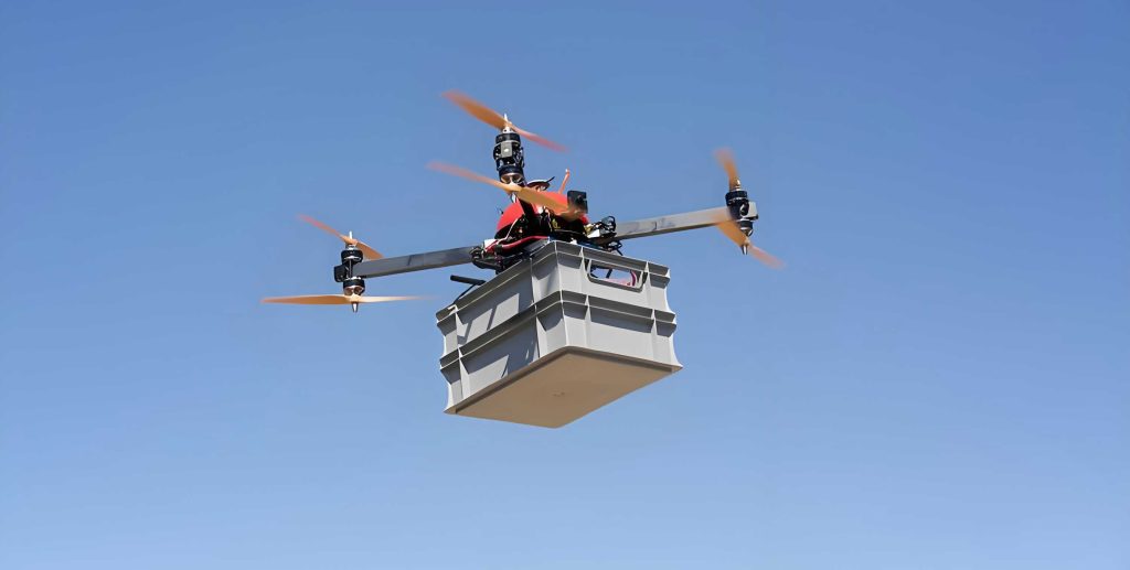
The standard imposes strict requirements on the testing equipment itself: firstly, the mass of the onboard measurement device must not exceed the UAV’s standard payload capacity; secondly, its loading method should not significantly affect the UAV’s center of gravity; and thirdly, the measurement accuracy of the equipment must be superior to the UAV’s specified performance by at least a factor of one-third or one order of magnitude. For a typical micro-UAV drone with a mass of 249g and a specified hovering accuracy of 0.1m (horizontal and vertical), the onboard device must weigh less than approximately 250g and achieve centimeter-level positioning accuracy. Existing systems fail primarily due to the high power consumption of their 4G cellular modems and associated web/Wi-Fi servers, necessitating large batteries and metallic casings for heat dissipation, which together contribute to the excessive mass.
The core innovation of our design lies in the systematic replacement of the high-power consumption components in a traditional RTK rover. The most significant power draw in conventional systems comes from the 4G/LTE module used for receiving differential corrections from the base station. We identified that the data throughput required for RTK is remarkably low. An RTK system operating at an update rate of 5 Hz, using a compact CMRx or RTCM 3.x message format, typically generates less than 1 kB/s of data. For testing ranges within 3 km, which is sufficient for most UAV drones flight tests, a low-power, long-range radio technology is perfectly adequate.
We selected LoRa (Long Range) technology to replace the 4G data link. LoRa operates in license-free ISM bands (e.g., 868 MHz, 915 MHz) and is renowned for its exceptional link budget and low power consumption. To validate the feasibility of this substitution, we conducted a link budget analysis for a typical urban testing scenario with a 3 km range and a UAV drones horizontal speed of up to 20 m/s. The path loss \(PL\) in decibels for a signal can be estimated using the simplified free-space path loss formula:
$$PL = 20\log_{10}(d) + 20\log_{10}(f) – 27.55$$
where \(d\) is the distance in meters (3000 m) and \(f\) is the frequency in MHz (868 MHz). This calculation yields:
$$PL = 20\log_{10}(3000) + 20\log_{10}(868) – 27.55 \approx 128 \text{ dB}$$
The link margin \(LM\), which indicates the system’s robustness, is calculated from the transmitter power \(P_{tx}\) (20 dBm), receiver sensitivity \(S_{rx}\) (-130 dBm for Spreading Factor 7, 125 kHz bandwidth), and the path loss:
$$LM = P_{tx} – S_{rx} – PL = 20 – (-130) – 128 = 22 \text{ dB}$$
A link margin exceeding 10 dB is generally considered robust for stable communication. Our calculated margin of 22 dB confirms that LoRa is more than capable of maintaining a stable data link for the RTK corrections under the specified dynamic conditions of the UAV drones flight, while consuming a fraction of the power of a 4G module. The following table compares the key characteristics of the 4G and LoRa communication approaches for this application.
| Parameter | 4G/LTE Module | LoRa Module (Our Design) |
|---|---|---|
| Typical Power Consumption (Active) | ~1.5 – 2 W | ~0.3 W (Rover), ~2 W (Base) |
| Data Rate | > 1 Mb/s | 0.3 – 50 Kb/s |
| Typical Range (Urban) | Several km (Cell-dependent) | 2 – 5 km |
| Operational Cost | SIM card & Data Plan | None (ISM Band) |
| Suitability for RTK Data | Overqualified, High overhead | Perfectly matched to requirement |
Hardware Architecture for Lightweight Onboard Rover
The design philosophy for the UAV drones -borne rover unit revolves around minimalism, low power, and distributed mass. The power savings from using LoRa directly enable the use of a smaller, lighter battery. To further reduce mass and footprint, we adopted a domestic system-on-chip (SoC) solution. The main processor is a Rockchip RV1106, a dual-core ARM Cortex-A35 chip capable of running a full-featured embedded Linux system while maintaining a controlled thermal profile and power budget below 1.2 W when unnecessary peripherals are disabled. This is a strategic choice supporting the broader goal of technological indigenization.
The hardware architecture is fundamentally distributed. Instead of a single enclosed unit, the rover’s components are separated into logical blocks: (1) the main computation and GNSS module containing the RV1106 and a multi-frequency GNSS receiver, (2) the LoRa communication module, and (3) the power supply unit. This allows the components to be strategically placed on the airframe of the UAV drones during testing—for instance, the GNSS antenna and main board on the top center, the battery on the underside for balance, and the LoRa module on an arm. This distributed loading minimizes the shift in the center of gravity of the UAV drones under test, a critical requirement of the standard. The total mass of the rover assembly, including a compact lithium polymer battery sufficient for over 2 hours of operation, is under 150 grams, well within the payload budget of micro UAV drones.
Software Implementation and RTK Processing Core
The software stack is built on a lightweight, custom-compiled Linux kernel (version 4.x) using the Buildroot framework. The kernel is meticulously configured by disabling debugging symbols (CONFIG_DEBUG_INFO=n), removing unused drivers, and enabling compression to minimize its size. The user-space application is a multi-threaded program written in C that manages data flow, RTK computation, and logging. The core software challenge is the reliable, low-latency integration of GNSS observation data with the incoming LoRa correction stream to produce a real-time high-accuracy position solution for the UAV drones.
The data processing pipeline is implemented through three synchronized threads, as summarized in the following workflow table.
| Thread Name | Primary Function | Data Source / Sink | Key Processing Step |
|---|---|---|---|
| RTCM Receiver | Reads differential correction data from the LoRa UART. | /dev/ttyS1 (LoRa) → RTKLIB engine |
Validates RTCM 3.x frame using CRC-24Q check. |
| RAWX Collector | Reads raw GNSS observations (pseudorange, carrier phase) from the receiver. | /dev/ttyS2 (GNSS) → Shared Memory Buffer |
Parses UBX-RAWX messages, time-aligns data using 1PPS signal. |
| RTK Solver | Performs high-precision position solution. | Shared Buffer + RTCM Data → rtkpos() |
Executes RTKLIB’s rtkpos() with EKF and ambiguity resolution. |
The threads communicate via ring buffers in shared memory, employing atomic operations for index management to minimize locking overhead. Mutual exclusion locks (pthread_mutex_t) protect critical sections, such as when sending configuration commands to the GNSS receiver. The core RTK engine is an integrated version of the open-source RTKLIB library. The solver thread calls the rtkpos() function, which employs an Extended Kalman Filter (EKF) to process the raw observations \( \mathbf{z} \) (pseudorange \( \rho \) and carrier phase \( \phi \)) and the state vector \( \mathbf{x} \) (position, velocity, clock bias, ambiguities \( \mathbf{N} \)).
The key measurement model for a given satellite \( i \) is:
$$
\begin{aligned}
\rho^i &= \|\mathbf{r}_{uav} – \mathbf{r}^i\| + c \cdot \delta t_u – c \cdot \delta t^i + I^i + T^i + \epsilon_{\rho} \\
\phi^i &= \|\mathbf{r}_{uav} – \mathbf{r}^i\| + c \cdot \delta t_u – c \cdot \delta t^i – I^i + T^i + \lambda N^i + \epsilon_{\phi}
\end{aligned}
$$
where \( \mathbf{r}_{uav} \) is the UAV drones position, \( \mathbf{r}^i \) is the satellite position, \( c \) is the speed of light, \( \delta t \) are clock errors, \( I \) and \( T \) are ionospheric and tropospheric delays, \( \lambda \) is the carrier wavelength, and \( \epsilon \) represents measurement noise. The RTCM corrections from the base station largely cancel out the atmospheric and satellite clock errors \( \delta t^i \), allowing the EKF to estimate the integer ambiguities \( N^i \) and resolve the UAV drones position \( \mathbf{r}_{uav} \) with centimeter-level accuracy. The final position solution is formatted into NMEA-0183 messages for logging and potential real-time downlink.
Robustness features include a watchdog timer for automatic system recovery and a heartbeat mechanism for the LoRa link that triggers a re-initialization sequence if corrections are lost for a predefined timeout period (e.g., 5 seconds).
System Validation and Performance Testing
The complete RTK system, comprising the LoRa-based base station and the lightweight UAV drones -borne rover, was subjected to rigorous static and dynamic testing. The primary objective was to verify that the use of LoRa did not degrade the positioning performance compared to traditional 4G-based RTK systems and that it met the accuracy requirements for testing UAV drones.
Static Test: The base station and the prototype rover were set up over known survey points approximately 1 km apart in an open environment. Both devices collected data for 120 minutes after achieving a fixed-integer RTK solution. The coordinates from our prototype were compared against those from a commercially available, metrologically verified RTK system serving as a reference. The statistical results of the coordinate differences are presented below.
| Error Component | Mean Error (cm) | Standard Deviation (cm) | RMS (cm) |
|---|---|---|---|
| Horizontal (2D) | 2.15 | 1.45 | 2.58 |
| Vertical (Height) | 3.82 | 2.91 | 4.79 |
The horizontal error is well within the 3 cm target, demonstrating that the LoRa link reliably delivers correction data without introducing significant latency or packet loss that would compromise RTK precision.
Dynamic Test: To simulate the conditions of a UAV drones in flight, the rover was mounted on a vehicle traveling along a 2 km straight-line trajectory at speeds exceeding 60 km/h (~16.7 m/s). The base station was positioned 1 km from the starting point. The trajectory calculated by our system was compared centimeter-by-centimeter against the trajectory from the reference system. The key performance metrics from the dynamic test are as follows.
| Performance Metric | Result |
|---|---|
| Average Horizontal Trajectory Error | 4.53 cm |
| Average Vertical Trajectory Error | 7.26 cm |
| Maximum Test Speed | ~61.5 km/h (17.1 m/s) |
| LoRa Link Stability | No dropouts, constant 1 Hz correction flow |
The slightly higher vertical error is typical for GNSS-based positioning but remains within an acceptable range for evaluating the vertical hold accuracy of most consumer UAV drones. The tests conclusively prove that the system maintains the required centimeter-level accuracy under dynamic conditions representative of UAV drones flight.
Conclusion
In response to the stringent requirements of new national standards for testing light and micro UAV drones, this work successfully designed and validated a novel, ultra-lightweight RTK detection system. By replacing power-hungry 4G communication with optimized LoRa technology and employing a low-power domestic SoC within a distributed hardware architecture, we achieved an onboard rover mass of less than 150 grams. This satisfies the critical payload and center-of-gravity constraints for testing modern micro UAV drones. Comprehensive static and dynamic testing confirmed that the system delivers horizontal positioning accuracy better than 3 cm, meeting and exceeding the precision requirements for evaluating UAV drones performance. The development provides a technically viable and practical blueprint for the indigenization of specialized testing equipment, demonstrating that performance-critical systems can be built with domestic cores while achieving superior suitability for targeted applications like UAV drones certification.