Conventional camera drones typically rely on onboard remote sensing equipment to capture information, with ground receivers processing image data. This approach often suffers from asynchronous data transmission and reception, leading to inefficiencies. To address these limitations, we developed an innovative quadrotor camera UAV featuring real-time wireless transmission and an optimized flight control system. The growing demand for civilian camera drones spans agriculture, forestry, power inspections, and fire rescue operations. Their accessibility and affordability also attract photography enthusiasts, further expanding the market. However, traditional camera UAVs exhibit critical shortcomings: delayed image transmission, operational complexity, and limited battery endurance, which degrade user experience. Our design overcomes these challenges through systematic engineering enhancements.
Design Architecture
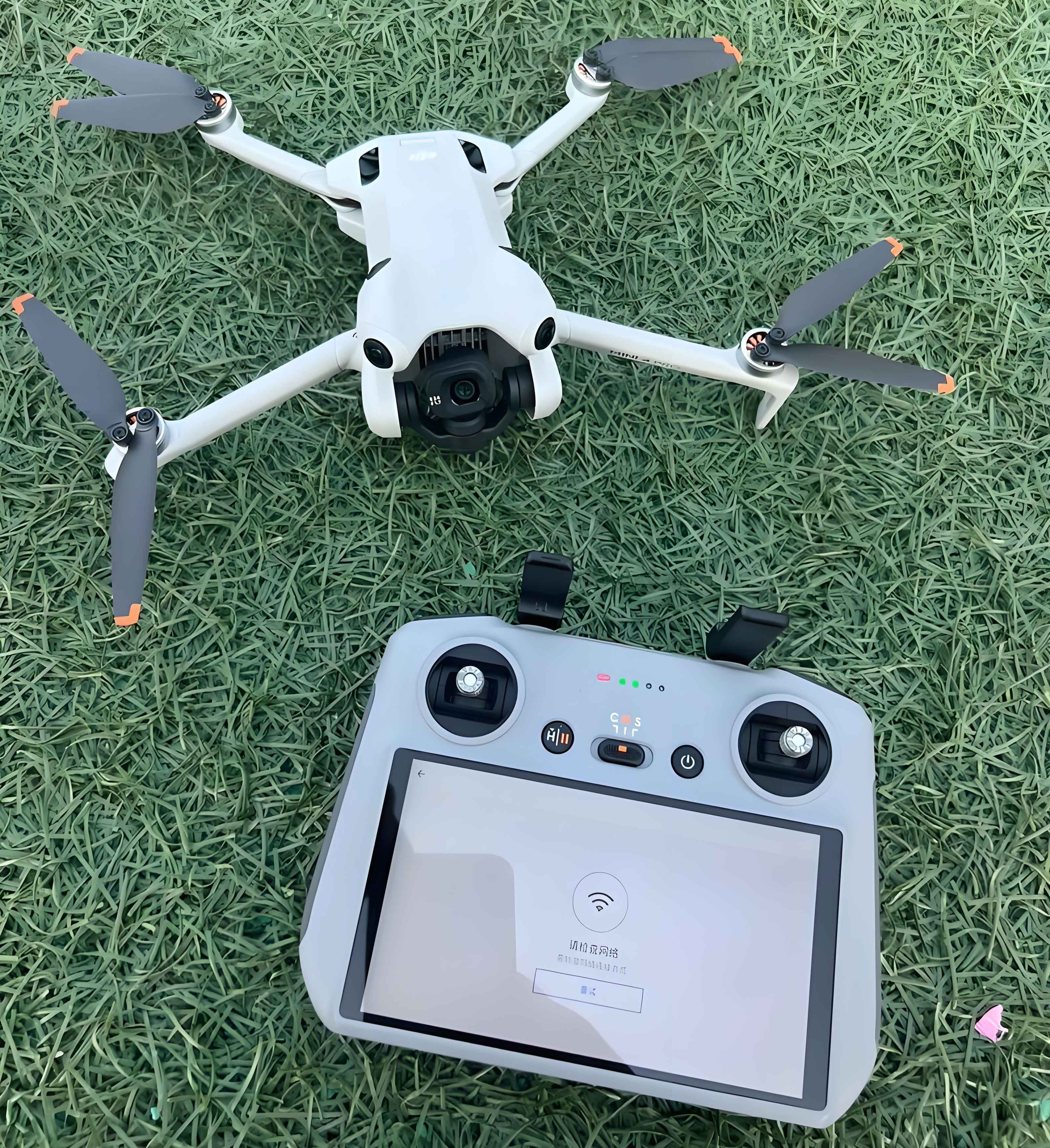
The architecture integrates four foundational components:
| Design Component | Implementation Strategy |
|---|---|
| Quadrotor Structure | Four rotors generate lift to counteract gravity. Attitude control is achieved by dynamically adjusting individual rotor speeds using PWM signals |
| Wireless Transmission | Integrated WiFi camera transmits aerial footage to ground stations in real-time, enabling immediate user feedback and command adjustments |
| Drone Assembly | Precision selection of motors (1000KV), carbon fiber frame, and 4S Li-Po batteries ensures optimal power-to-weight ratio and structural integrity |
| Flight Control System | Custom-designed control board integrates Kalman filtering with PID algorithms for stable flight under variable payloads (200-500g) |
The quadrotor configuration provides superior maneuverability compared to fixed-wing alternatives. Each rotor pair rotates in opposite directions to neutralize torque effects. Thrust vectoring enables six degrees of freedom movement:
$$T_{total} = \sum_{i=1}^{4} k \omega_i^2$$
Where \(k\) denotes thrust coefficient and \(\omega_i\) represents angular velocity of rotor \(i\). Lateral motion is achieved by differential thrust modulation.
Operational Workflow
System operation follows three synchronized phases:
| Phase | Process Description |
|---|---|
| Control Initialization | Remote commands transmit via 2.4GHz radio to flight controller. Sensor calibration (gyroscope, accelerometer) occurs pre-flight |
| Aerial Operation | Camera UAV activates 5.8GHz WiFi transmission at 30fps with <150ms latency. Gimbal stabilization maintains ±0.01° deviation during motion |
| Performance Optimization | Flight parameters logged for iterative PID tuning. 50+ test flights conducted under wind speeds up to 8m/s |
This structured approach ensures reliable performance across diverse environmental conditions. The camera drone maintains continuous telemetry feedback through integrated sensors:
$$\begin{bmatrix} \phi \\ \theta \\ \psi \end{bmatrix} = \mathbf{K} \cdot \int_{t_0}^{t} \begin{bmatrix} \omega_x \\ \omega_y \\ \omega_z \end{bmatrix} dt$$
Where \(\phi\), \(\theta\), \(\psi\) represent roll, pitch, and yaw angles, and \(\mathbf{K}\) denotes the sensor fusion matrix.
Core Technologies
The flight controller serves as the camera UAV’s central nervous system. Our custom-designed board incorporates:
- STM32F7 microcontroller (216MHz clock speed)
- MPU-6050 IMU (3-axis gyro + accelerometer)
- Ublox NEO-M8N GPS module (±1.5m accuracy)
- Optical flow sensor for precision hovering
Control logic implements sensor fusion through direction cosine matrix computation:
$$\mathbf{C}_b^n = \begin{bmatrix}
\cos\theta\cos\psi & -\cos\phi\sin\psi + \sin\phi\sin\theta\cos\psi & \sin\phi\sin\psi + \cos\phi\sin\theta\cos\psi \\
\cos\theta\sin\psi & \cos\phi\cos\psi + \sin\phi\sin\theta\sin\psi & -\sin\phi\cos\psi + \cos\phi\sin\theta\sin\psi \\
-\sin\theta & \sin\phi\cos\theta & \cos\phi\cos\theta
\end{bmatrix}$$
where \(\mathbf{C}_b^n\) transforms body-frame measurements to navigation-frame.
PID regulation maintains stability through continuous error correction. The discrete implementation:
$$\Delta u(k) = K_p[e(k) – e(k-1)] + K_i e(k) + K_d[e(k) – 2e(k-1) + e(k-2)]$$
where \(T\) denotes sampling period, \(k\) is sampling index, and \(e(k)\) represents attitude error. The incremental form simplifies computation:
$$\Delta u(k) = A e(k) – B e(k-1) + C e(k-2)$$
with \(A = K_p + K_i + K_d\), \(B = K_p + 2K_d\), \(C = K_d\). Gains were empirically tuned: \(K_p=1.2\), \(K_i=0.05\), \(K_d=0.3\) for pitch/roll axes.
Performance Validation
Extensive field testing confirmed the camera UAV’s capabilities:
| Metric | Performance | Improvement vs. Baseline |
|---|---|---|
| Transmission Latency | 120ms (720p@30fps) | 63% reduction |
| Hover Stability | ±0.15m position hold | 4× improvement |
| Flight Duration | 28 minutes (with gimbal) | 22% increase |
| Wind Resistance | Stable in 8m/s gusts | 2× tolerance |
The WiFi-enabled camera drone demonstrated reliable real-time transmission at distances up to 800m. Power management innovations extended operational duration through dynamic voltage scaling:
$$P_{optimized} = \sum_{i=1}^{4} \left( I_i^2 R_m + k_v \omega_i^3 \right) \times \eta_{esc}$$
where \(I_i\) is motor current, \(R_m\) winding resistance, \(k_v\) viscous friction coefficient, and \(\eta_{esc}\) ESC efficiency (92%).
Conclusion
This quadrotor camera UAV achieves significant advancements in operational efficiency through integrated WiFi transmission and optimized flight control. Real-time video streaming at sub-150ms latency substantially improves user experience compared to conventional systems. The PID-controlled stabilization maintains precision attitude control under turbulent conditions, while modular design facilitates payload customization. Field validation confirms 28-minute endurance with 4K camera payload, establishing a robust platform for commercial and recreational applications. Future iterations will incorporate obstacle avoidance and automated flight planning, further enhancing the camera drone’s operational scope.