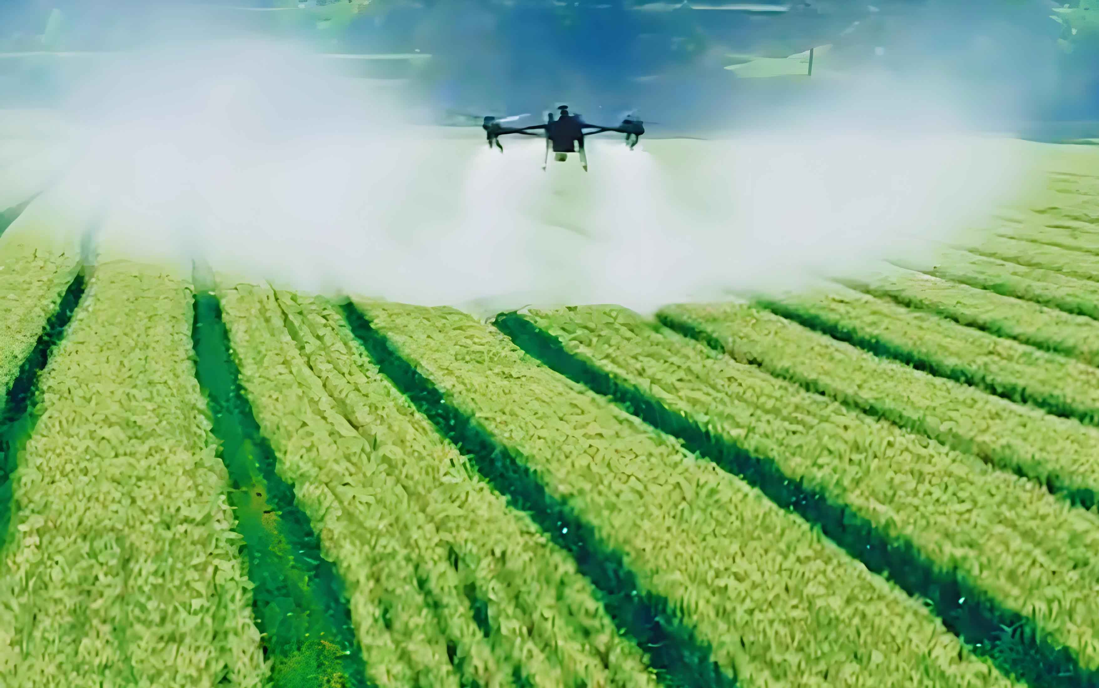
The adoption of agricultural UAV technology has seen rapid growth globally, representing a significant shift in modern precision agriculture practices. Compared to traditional ground-based sprayers, agricultural UAVs offer notable advantages, including superior droplet penetration into crop canopies, high operational efficiency over challenging terrain, and the potential for reduced chemical usage. In nations with large-scale farming, the fleet of agricultural UAVs has expanded dramatically, becoming a cornerstone of crop protection strategies. However, a critical challenge that persists and threatens the sustainability of this technology is spray droplet drift. Drift refers to the movement of pesticide droplets away from the intended target area, leading to economic loss through wasted chemicals, environmental contamination of soil and water bodies, and potential damage to non-target crops and ecosystems.
Current research and development for agricultural UAVs often prioritize aspects such as deposition uniformity, nozzle design, and overall platform optimization. While these are crucial, a more fundamental and theoretical understanding of the spray application process itself, particularly under the influence of the unique downwash airflow generated by multi-rotor systems, remains at a preliminary stage. The lack of standardized operational parameters—such as optimal nozzle specifications, flight altitude, and rotor speed for given conditions—leads to inconsistent and often suboptimal field practices. Operating without scientifically validated guidelines increases the risk of excessive drift. Therefore, systematically investigating the factors governing droplet drift for agricultural UAVs is essential for developing best practices and technological improvements.
This article presents the design and implementation of a dedicated indoor test bench to study droplet drift from a multi-rotor agricultural UAV. The core objective is to isolate and analyze the influence of key operational parameters, specifically rotor speed (and its resultant downwash velocity) and spray pressure, on the drift propensity of droplets. By establishing measurable correlations, this research aims to contribute foundational knowledge that can guide the optimization of spray application protocols for agricultural UAVs, ultimately promoting efficient chemical use and minimizing environmental impact.
1. Design and Implementation of the Agricultural UAV Drift Test Bench
A controlled experimental setup is paramount for isolating specific variables affecting drift. The test bench was designed to facilitate detailed measurement of the UAV’s downwash airflow and subsequent quantification of droplet drift under various settings.
1.1 Core Components and Specifications
The test system centered on a commercially available hexacopter agricultural UAV, representative of common platforms in use. Key specifications of the system components are summarized in Table 1.
| Main Component | Item | Technical Specification |
|---|---|---|
| Agricultural UAV (Hexacopter) | Tank Capacity | 15.1 L (Rated), 20 L (Max) |
| Rotor Speed Range | 590 – 2300 rpm | |
| Frame Size | 2509 mm × 2213 mm × 732 mm | |
| Mini Anemometer | Measurement Range | 0 – 30 m/s |
| Accuracy | ±5% of reading | |
| Standard Flat Fan Nozzle (SX11001VS) | Spray Angle | 110° |
| Operating Pressure Range | 0.2 – 0.4 MPa | |
| Flow Rate Range | 0.32 – 0.45 L/min | |
| Droplet Size (VMD) | 130 – 250 µm | |
| Lift Platform | Height Adjustment Range | 2700 – 3900 mm |
| Platform Size | 3.5 m × 2.6 m |
1.2 Downwash Airflow Velocity Measurement
Characterizing the airflow generated by the agricultural UAV is the first step, as this downwash is the primary carrier and influencer of droplet trajectories. The UAV was mounted on a stationary lift platform at a fixed height. A three-dimensional coordinate system was established with the origin directly below the UAV’s center. Velocity measurements were taken at multiple points in radial and vertical directions beneath the rotors. Measurements were repeated three times per point under stabilized rotor speeds of 590 rpm, 1590 rpm, and 2230 rpm to capture the velocity field structure.
1.3 Drift Collection and Quantification System
To measure drift, a ground-based collection apparatus was positioned beneath the agricultural UAV. The apparatus consisted of a primary V-shaped trough (4m x 4m) aligned to capture droplets within the effective swath. A key design consideration was mitigating droplet rebound. The trough was set at a 15° incline to allow liquid to drain by gravity into a collection container. A secondary container was placed vertically at the end of the trough to catch any droplets deflected horizontally. After each spray test, liquid deposited in the trough was collected using a rubber squeegee and combined with the liquid in the secondary container. The total mass of recovered spray (D) was weighed using a high-precision electronic balance (d=0.01g). The spray application operated in a “3-1” cycle: 3 minutes of spraying followed by 1 minute of drainage and collection.
2. Analysis of Downwash Flow Field for an Agricultural UAV
The airflow pattern from a multi-rotor agricultural UAV is complex due to the interaction of multiple rotors. Computational Fluid Dynamics (CFD) simulation provides valuable insight into this flow field before physical measurement.
2.1 CFD Simulation Setup
A 1:1 scale 3D model of the hexacopter agricultural UAV was created. For simulation efficiency and clarity, assumptions were made: air was treated as incompressible, and changes in air density and temperature were neglected. The computational domain was discretized using a Cartesian grid, with a finer mesh in the rotor regions. The Multiple Reference Frame (MRF) model was applied to simulate rotor rotation. The simulation solved the steady-state Reynolds-Averaged Navier-Stokes (RANS) equations to predict the velocity field at different rotor speeds.
2.2 Simulation and Measured Results
The CFD results visualized the development of the downwash. Near the rotor plane (within ~1m), individual rotor wakes were distinct. As the flow propagated downward, these wakes began to interact and merge, forming a more consolidated turbulent column of air below the agricultural UAV. The measured data from the anemometer validated the general trends observed in simulation. The measured average air velocities at key heights for the three rotor speeds are summarized below:
Key Finding: The downwash velocity increases proportionally with rotor speed and decays with increasing distance from the agricultural UAV. The maximum velocity in a horizontal plane typically occurs at a radial distance corresponding to the rotor tip path before diminishing towards the center and outer edges. At the highest tested rotor speed (2230 rpm), significant airflow (0-10 m/s) was still detectable at ground level, confirming the powerful influence of the agricultural UAV on the near-ground micro-environment.
3. Experimental Investigation of Droplet Drift Dynamics
With the airflow characterized, the focus shifted to quantifying how this airflow, combined with spray parameters, affects droplet drift. The primary evaluation metric was the Drift Fraction (D_f).
3.1 Drift Fraction Definition
The Drift Fraction represents the proportion of the total sprayed volume that is lost from the target zone. It is calculated using the following formula:
$$
D_f = \frac{Q – D}{Q} \times 100\%
$$
where:
\( D_f \) = Drift Fraction (%)
\( Q \) = Total mass of spray liquid released (g)
\( D \) = Total mass of spray liquid collected in the ground apparatus (g)
A lower \( D_f \) indicates better deposition on target and less drift. The total sprayed mass \( Q \) for a given pressure was determined by collecting spray directly from the nozzle in a beaker over the same 3-minute period, effectively eliminating drift during calibration. The values for different pressures are shown in Table 2.
| Spray Pressure (MPa) | Spray Flow Rate (mL/min) | Total Sprayed Mass, Q (g) in 3 min |
|---|---|---|
| 0.2 | 256 | 768.9 |
| 0.3 | 312 | 936.4 |
| 0.4 | 360 | 1080.3 |
3.2 Experimental Design and Test Matrix
The experiment was designed to evaluate the individual and combined effects of rotor speed and spray pressure on drift. The agricultural UAV was held at a constant altitude. The test matrix included:
- Rotor Speed: Four levels (0 rpm as a static/no-downwash control, 590 rpm, 1590 rpm, 2230 rpm).
- Spray Pressure: Three levels (0.2 MPa, 0.3 MPa, 0.4 MPa).
Each combination of parameters was tested with three replicates to ensure statistical reliability. The results are presented in Table 3.
| Spray Height (mm) | Spray Pressure (MPa) | Drift Fraction, D_f (%) | |||
|---|---|---|---|---|---|
| Rotor Speed: 0 rpm | Rotor Speed: 590 rpm | Rotor Speed: 1590 rpm | Rotor Speed: 2230 rpm | ||
| 3100 | 0.2 | 9.30 | 7.75 | 8.91 | 8.51 |
| 0.3 | 12.28 | 10.24 | 11.77 | 11.34 | |
| 0.4 | 14.31 | 11.93 | 13.71 | 13.26 | |
4. Results and Discussion: Parameter Influence on Drift
Analysis of the data from Table 3 reveals clear trends regarding how the operation of an agricultural UAV influences droplet drift.
4.1 Influence of Rotor Speed (Downwash Airflow)
Contrary to a simplistic view that stronger wind causes more drift, the data shows a nuanced relationship within the context of a hovering agricultural UAV. When comparing tests with active downwash (590, 1590, 2230 rpm) to the static control (0 rpm), a clear trend emerges: the presence of downwash generally reduced the drift fraction compared to spraying with no airflow.
Mechanism: The downwash from the agricultural UAV creates a dominant vertical airflow column that pushes droplets downward toward the target area with greater momentum. This reduces the time droplets are suspended in air and susceptible to horizontal displacement by ambient turbulence, thereby reducing drift. At the lowest operational rotor speed (590 rpm), the drift fraction was minimized for all pressures. However, this speed represents an idle condition insufficient for actual flight. At practical flight speeds (1590 and 2230 rpm), the drift fraction was slightly higher than at 590 rpm but still lower than the static spray case for most conditions.
The comparison between 1590 rpm and 2230 rpm is particularly instructive. At the higher rotor speed (2230 rpm), the drift fraction was consistently lower than at 1590 rpm. This suggests that beyond a certain threshold, a stronger, more coherent downwash can further enhance droplet deposition and containment within the spray swath. However, it is critical to note that excessive downwash at very low altitudes can cause droplet rebound and splash from hard surfaces or dense canopy, which was partially mitigated by the design of the collection trough in this experiment.
4.2 Influence of Spray Pressure
The effect of spray pressure was more direct and consistent across all rotor speeds. Increasing the spray pressure led to a significant increase in the drift fraction.
Mechanism: Higher spray pressure produces finer droplets (smaller Volume Median Diameter, VMD). According to the Stokes’ law approximation for droplet settling, the terminal velocity \( v_t \) of a droplet is proportional to the square of its diameter:
$$
v_t \propto d^2
$$
where \( d \) is the droplet diameter. Finer droplets have a drastically lower terminal velocity. Therefore, they remain airborne longer and are more easily carried away by even mild horizontal air movements or turbulent eddies within the agricultural UAV‘s own downwash, leading to higher drift. This result underscores the critical importance of nozzle selection and pressure management for low-drift operations with agricultural UAVs.
4.3 Interaction of Parameters and Optimal Condition
The study demonstrates that drift from an agricultural UAV is not governed by a single factor but by the interaction of the spray quality (determined by pressure) and the airflow management (determined by rotor speed/flight mode). For the tested agricultural UAV and nozzle type under the specified indoor conditions (no crosswind, fixed height), the combination that yielded the lowest measurable drift fraction was a spray pressure of 0.2 MPa and the highest practical rotor speed of 2230 rpm. This setting produced relatively larger droplets (lower drift propensity) and employed a strong downwash to rapidly convey them to the target zone.
5. Conclusion and Future Perspectives
This research successfully designed and utilized a dedicated test bench to analyze the drift performance of an agricultural UAV. The experimental approach allowed for the systematic isolation and study of key operational parameters. The main conclusions are:
- Downwash is a Double-Edged Sword: The airflow generated by an agricultural UAV is fundamental to its application process. While it can be a source of turbulent energy that promotes drift, when properly harnessed (through appropriate rotor speed and flight altitude), it serves as a primary vector for delivering droplets to the target and can significantly reduce drift compared to a scenario with no induced airflow.
- Spray Pressure is a Critical Drift Lever: Lower spray pressures, which generate larger droplet spectra, are a highly effective method for minimizing drift from agricultural UAVs, as confirmed by the strong positive correlation between pressure and drift fraction.
- Parameter Optimization is Key: Optimal spray application with an agricultural UAV requires a balanced combination of parameters. The findings suggest that operators should favor lower spray pressures and utilize sufficient rotor speed to create a stabilizing downwash, all while maintaining an appropriate flight height to avoid rebound.
The study provides a foundational framework and quantitative data to inform the development of standardized, low-drift operation guidelines for agricultural UAVs. Future work should expand to include the effects of crosswind, different nozzle types (e.g., air-induction), varying flight altitudes and forward speeds, and diverse canopy architectures. Integrating such factors will lead to more robust models and decision-support systems for precision spray application, ensuring the sustainable and efficient use of agricultural UAV technology in global agriculture.