The contemporary unmanned aerial vehicle (UAV) landscape is predominantly bifurcated into two archetypes: rotary-wing and fixed-wing platforms. Each possesses a distinct set of advantages and inherent limitations, often making them specialists rather than generalists. The rotary-wing VTOL drone, exemplified by ubiquitous multirotor designs, offers unparalleled maneuverability, including vertical takeoff and landing (VTOL), precise hovering, and omnidirectional flight. These traits make it ideal for tasks like close-range inspection, aerial photography, and operations in confined spaces. However, its fundamental aerodynamic inefficiency, where lift is generated entirely through rotor thrust, results in significantly shorter endurance and range, limiting its utility for long-distance or prolonged missions. Conversely, the fixed-wing VTOL drone leverages the aerodynamic efficiency of a wing to generate lift, enabling substantially longer flight times, greater speeds, and superior range with the same energy expenditure. Its primary drawback is the requirement for a runway or launcher for takeoff and landing, constraining its deployment in rugged, remote, or urban environments lacking prepared infrastructure.
The growing operational demands across sectors such as rapid medical supply delivery, emergency response, infrastructure monitoring, and precision agriculture increasingly call for a platform that transcends these traditional compromises. Missions frequently involve navigating complex, variable environments where a prepared landing strip is a luxury and where the operational area may be both distant and require detailed, low-speed observation. This gap in capability underscores the pressing need for a hybrid solution—a convergent VTOL drone that intelligently merges the vertical agility of rotors with the cruise efficiency of a fixed wing. This document details the first-person design philosophy, structural implementation, and optimization pathways for such a hybrid VTOL cargo drone, developed to address these multifaceted operational challenges.
| Feature | Rotary-Wing (Multirotor) | Fixed-Wing | Hybrid VTOL (This Design) |
|---|---|---|---|
| Takeoff/Landing | Vertical (VTOL), minimal space | Requires runway/launcher | Vertical (VTOL), minimal space |
| Hovering Capability | Excellent | None | Excellent in VTOL mode |
| Cruise Efficiency | Low (high power consumption) | High (low power consumption) | High in fixed-wing mode |
| Endurance & Range | Short (typically < 45 min) | Long (several hours possible) | Extended (leveraging fixed-wing cruise) |
| Cruise Speed | Low to Moderate | High | |
| Mission Flexibility | High in confined spaces | Low for spot observation | Very High (multi-mode) |
| Operational Complexity | Low (simpler control) | Medium (requires launch/recovery) | Medium (managed by flight controller) |
Design Philosophy and Functional Specifications
Our primary objective was to engineer a VTOL drone that does not merely combine two systems but integrates them into a cohesive, efficient, and robust platform. The core design tenets are defined by the following functional specifications:
- Seamless Multimodal Operation: The aircraft must transition reliably between a rotor-dominated VTOL/hover mode and a wing-dominated cruise mode. This involves not only mechanical design but, crucially, sophisticated flight control algorithms to stabilize the inherently unstable transition phase.
- Structural and Operational Efficiency: The airframe must be lightweight yet strong, minimizing parasitic drag in cruise while withstanding the loads of vertical lift. The propulsion system must be optimized for both high-thrust vertical flight and efficient forward propulsion.
- Modular Payload System: Recognizing diverse mission profiles, the cargo/payload interface is designed for modularity. This allows rapid reconfiguration between, for example, a medical supply capsule, a multispectral sensor pod, or a communications relay, enhancing the VTOL drone‘s utility.
- Enhanced Maneuverability and Stability: Beyond basic flight, the design incorporates control strategies like differential thrust for agile in-plane turns and an integrated flight controller (FC) to provide stability augmentation, simplifying pilot operation and compensating for environmental disturbances.
- Manufacturability and Maintainability: The design prioritizes a construction methodology that reduces permanent adhesives, utilizes interlocking modules, and employs accessible components to simplify assembly, field repair, and future upgrades.
Airframe Architecture and Hybrid Configuration
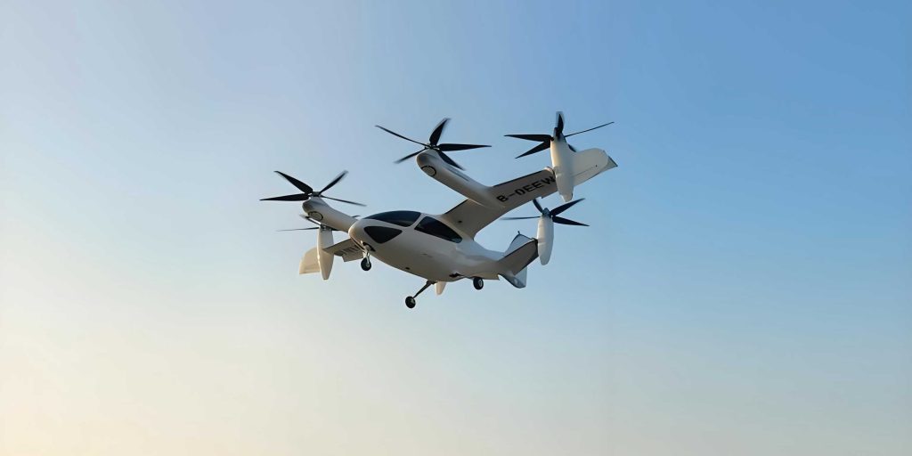
The selected configuration for this VTOL drone is a tail-sitter, dual-motor, fixed-wing hybrid. This choice offers a mechanically simple solution compared to tilt-rotor or lift+cruise designs, as it eliminates complex tilting mechanisms. The entire airframe rotates 90 degrees between vertical and horizontal flight attitudes.
The core airframe is a conventional fixed-wing design optimized for efficient cruise. Key features include:
- Wing: A high-aspect-ratio, double-curvature airfoil section is employed. High aspect ratio reduces induced drag for endurance, expressed as $AR = \frac{b^2}{S}$, where $b$ is wingspan and $S$ is wing area. The symmetrical airfoil provides consistent performance in both upright and inverted (VTOL mode) attitudes.
- Construction: The primary longitudinal spars are a composite of carbon fiber rods and square balsa wood. The carbon fiber provides exceptional tensile strength and stiffness-to-weight ratio, while the balsa wood serves as a practical substrate for precisely locating and attaching other components, such as ribs and skin, without specialized tooling. Connections between major parts are made using custom-designed, interlocking hardwood blocks, minimizing the use of permanent adhesive and facilitating disassembly.
- Control Surfaces: Conventional ailerons and an elevator (functioning as rudder in VTOL mode) are fabricated from lightweight balsa and covered with heat-shrink film. They are hinged using flexible tape for minimal slop and fast response. The vertical stabilizer provides directional stability in forward flight.
The VTOL capability is granted by two powerful brushless motors mounted on the wing leading edges, directly driving propellers optimized for static thrust. In the tail-sitter configuration, these motors provide all lift during vertical flight.
| Component | Primary Material | Key Function | Design Rationale |
|---|---|---|---|
| Main Spar | Carbon Fiber Rod & Balsa | Primary bending load bearer | High stiffness/weight; balsa allows easy bonding |
| Wing Ribs | Balsa Sheet | Maintain airfoil shape, attach skin | Lightweight, easy to cut and shape |
| Control Surfaces | Balsa Sheet & Film | Provide pitch/roll/yaw control | Lightweight, low inertia for fast response |
| Motor Mounts | CNC-cut Plywood | Secure motors to wing | High strength to handle thrust vibration |
| Fuselage Pod | Balsa/Depron Sheet | House electronics, payload | Lightweight, modular design |
| Landing Gear / VTOL Supports | Carbon Fiber Rods | Protect airframe during vertical landing | High strength, elastic deformation absorbs shock |
Modular Payload and Release Mechanism
A central mission for this VTOL drone is light cargo transport and precise aerial delivery. The payload system is designed as a self-contained, modular bay located at the aircraft’s center of gravity (CG).
- Payload Bay: Consists of a lightweight frame that can accommodate standardized containers. The bay is positioned such that the CG shift from loading or releasing a payload is minimal, ensuring stable flight characteristics.
- Shock Mitigation: The bay is suspended via flexible carbon fiber rods attached to the main airframe. These rods act as dampers, elastically deforming upon landing impact to isolate the payload and sensitive electronics from high-G shocks.
- Release Mechanism: The release is actuated by a compact, high-torque servo motor. A carbon fiber pin, attached to the servo arm, engages with a latch on the payload container. Upon command, the servo rotates, retracting the pin and releasing the payload. The mechanism’s simplicity ensures high reliability. The release force and timing can be modeled by the servo torque $\tau$ and the lever arm distance $r$: $F_{release} = \frac{\tau}{r}$.
Aerodynamic and Propulsive Principles
The performance envelope of this hybrid VTOL drone is governed by distinct aerodynamic regimes.
1. VTOL/Hover Mode: Lift is generated entirely by rotor thrust, analogous to a multirotor. The total thrust $T$ required to hover is equal to the total weight $W$ of the aircraft. For dual motors, each must provide $T_{motor} = \frac{W}{2}$. The power required in hover $P_{hover}$ is high and can be estimated by momentum theory:
$$P_{hover} \approx \frac{T^{3/2}}{\sqrt{2 \rho A}}$$
where $\rho$ is air density and $A$ is total propeller disk area. This explains the high energy consumption in this mode.
2. Cruise Mode: In forward flight, lift $L$ is generated by the wing:
$$L = \frac{1}{2} \rho V^2 S C_L$$
where $V$ is airspeed, $S$ is wing area, and $C_L$ is the lift coefficient. The required thrust from the motors now only needs to overcome the total drag $D$:
$$T_{cruise} = D = \frac{1}{2} \rho V^2 S (C_{D0} + k C_L^2)$$
Here, $C_{D0}$ is parasitic drag and $k C_L^2$ represents induced drag. Since $D \ll W$, the power required for cruise $P_{cruise}$ is significantly lower than $P_{hover}$, enabling extended endurance.
3. Differential Thrust Yaw Control: A key maneuverability feature in cruise mode is the use of differential motor speed for yaw control. By creating a thrust differential $\Delta T$ between the two motors, a yawing moment $N_{diff}$ is generated:
$$N_{diff} = \Delta T \cdot d$$
where $d$ is the lateral distance between the motor shafts. This allows for coordinated turns without relying solely on the control surface (rudder), reducing drag and enabling tighter turn radii. The flight controller can mix this differential throttle input with aileron input for banked turns.
Flight Control System and Mode Transition
The operational intelligence of this VTOL drone resides in its integrated Flight Controller (FC), running specialized firmware (e.g., ArduPilot, PX4). The FC manages three critical phases:
- VTOL Stabilization: Using data from an Inertial Measurement Unit (IMU—gyroscopes, accelerometers) and a magnetometer, the FC stabilizes the aircraft in hover. It actively adjusts motor speeds and control surface deflections (which act as vanes in this mode) to counteract wind gusts and maintain position and heading.
- Automated Transition: This is the most critical phase. Upon pilot command, the FC executes a pre-programmed maneuver. The aircraft, while in hover, uses its elevator control surface to pitch forward. As it gains forward speed, wing-borne lift increases. The FC automatically and gradually reduces motor power as lift transfers from the rotors to the wing. The process is reversed for transitioning back to hover. The FC manages this dynamic cross-fading of lift sources to prevent a stall or uncontrolled descent.
- Fixed-Wing Flight Augmentation: In cruise mode, the FC provides stability augmentation (like a “co-pilot”), dampening oscillations and maintaining level flight. It also enables advanced features like autonomous waypoint navigation, return-to-home, and loiter patterns.
The control laws within the FC often employ Proportional-Integral-Derivative (PID) loops. For example, the algorithm to maintain pitch angle $\theta$ to a desired setpoint $\theta_{des}$ might be:
$$u_{pitch} = K_p(\theta_{des} – \theta) + K_i\int(\theta_{des} – \theta)dt + K_d\frac{d}{dt}(\theta_{des} – \theta)$$
where $u_{pitch}$ is the output command to the elevator servo, and $K_p$, $K_i$, $K_d$ are tuned gains.
| Flight Mode | Primary Actuators | Primary Sensors | FC Core Function |
|---|---|---|---|
| VTOL / Hover | Motor 1 & 2 (Thrust), Control Surfaces (Vanes) | IMU, Barometer, GPS (for hold) | 3-Axis Attitude Stabilization, Position Hold |
| Transition (VTOL→FW) | Motors (reducing), Elevator (pitching) | IMU, Airspeed Sensor | Manage lift transfer, prevent stall, maintain safe pitch |
| Cruise (Fixed-Wing) | Motors (balanced), Ailerons, Elevator, Rudder | IMU, GPS, Airspeed Sensor | Navigation, Stability Augmentation, Autonomous Flight |
| Transition (FW→VTOL) | Motors (increasing), Elevator (flaring) | IMU, Barometer, GPS | Slow airspeed, increase thrust, stabilize for hover |
Fabrication Process and Optimization Pathways
The build process follows a modular, layer-by-layer approach, emphasizing precision and serviceability.
- Skeleton Assembly: The carbon fiber/balsa main spars and ribs are joined using the interlocking hardwood blocks and pinned with cyanoacrylate for key joints only. This creates a rigid, lightweight framework.
- Skinning: The wings and fuselage are covered with heat-shrink polyester film, which tightens when heated, providing a smooth, rigid, and lightweight shell. The heat also slightly bonds the film to the balsa structure.
- Systems Integration: Motors, servos, the flight controller, GPS module, radio receiver, and telemetry system are installed. Wiring is routed neatly and secured. The payload release servo is integrated with the modular bay.
- Software Configuration: The flight controller firmware is configured with parameters specific to the airframe’s weight, dimensions, and motor performance. Control gains are tuned, and flight modes are assigned to transmitter switches.
Several key optimizations were identified and implemented:
- Weight Reduction: Every component was scrutinized. Holes were cut in non-critical structural parts (e.g., servo tray), and excess material was removed. The interlocking block system itself saves weight by replacing heavy glue fillets.
- Drag Reduction: Care was taken to ensure a smooth skin finish. All wires and components were faired in. The landing support rods were designed to be as slender as possible while maintaining strength.
- Center of Gravity (CG) Management: Precise CG location is paramount, especially for a tail-sitter. Components were arranged to place the CG slightly ahead of the aerodynamic center for inherent pitch stability in forward flight. The modular payload bay is located precisely at this CG point.
Further optimization can be explored mathematically. For instance, to maximize endurance in cruise, one seeks to fly at the speed for minimum power required, which for a propeller-driven aircraft is often close to the speed for maximum lift-to-drag ratio $\left(\frac{L}{D}\right)_{max}$. The endurance $E$ can be approximated by:
$$E \approx \frac{\eta_{prop}}{c} \frac{C_L^{3/2}}{C_D} \sqrt{\frac{2 \rho S}{W}} \left( \sqrt{\frac{W}{S}} – \sqrt{\frac{W_{empty}}{S}} \right)$$
where $\eta_{prop}$ is propeller efficiency, $c$ is the specific fuel consumption (or battery energy equivalent), $W$ is total weight, and $W_{empty}$ is empty weight. This formula highlights the critical importance of a high $L/D$ ratio, low structural weight ($W_{empty}$), and efficient propulsion.
| Parameter | Symbol | Optimization Goal | Method/Design Choice |
|---|---|---|---|
| Structural Mass | $m_{struct}$ | Minimize | Carbon fiber/balsa composite; hollow construction |
| Aerodynamic Efficiency | $L/D$ | Maximize | High-aspect-ratio wing; smooth finish; streamlined pod |
| Propulsive Efficiency (Cruise) | $\eta_{prop}$ | Maximize | Propeller matched to motor & cruise speed |
| Static Thrust (VTOL) | $T_{static}$ | $T_{total} > 1.5 \cdot W$ | High KV motors with large-pitch propellers |
| Control Authority | – | Sufficient for transition/wind | Large control surfaces; differential thrust mixing |
| Battery Energy Density | – | Maximize (Wh/kg) | Use of high-C-rate Lithium-Polymer (LiPo) packs |
Conclusion and Future Development
The design, fabrication, and testing of this hybrid VTOL cargo drone validate the feasibility and utility of converging rotary and fixed-wing technologies into a single, versatile platform. It successfully addresses the core limitation of runway dependency while overcoming the endurance penalty of pure rotary-wing flight. The integration of a modern flight controller is not merely an addition but a fundamental enabler, transforming a complex, unstable hybrid airframe into a manageable and reliable tool.
This project lays a foundation for several promising avenues of future development. Aerodynamic refinement through computational fluid dynamics (CFD) analysis could further optimize the wing-fuselage junction and the design of the motor nacelles. The propulsion system could evolve towards a more efficient hybrid-electric or multi-mode system, perhaps with dedicated high-RPM lift rotors and a separate low-RPM cruise propeller. The modular payload system’s scope can be expanded with standardized mechanical and electronic interfaces (e.g., USB-C or Ethernet for power/data) to support a wider ecosystem of sensors and delivery mechanisms. Finally, advancing the autonomy stack to enable fully automatic perception-aware landing in complex terrain would represent a significant leap in operational capability.
In essence, the hybrid VTOL drone represents a pragmatic and powerful synthesis of existing technologies. It is an embodiment of the engineering philosophy that the most effective solution often lies not in choosing between two good options, but in finding an elegant and intelligent way to harness the strengths of both. As battery technology, materials science, and artificial intelligence continue to advance, this class of aircraft is poised to become an increasingly indispensable asset across civilian and commercial domains.