
The evolution of unmanned aerial vehicles (UAVs) has been significantly propelled by advances in micro-electromechanical systems (MEMS) and embedded processing. Among various configurations, the quadrotor drone stands out due to its mechanical simplicity, capability for vertical takeoff and landing (VTOL), and excellent maneuverability. However, achieving robust and reliable autonomous flight, particularly during the critical phases of takeoff and landing, remains a complex challenge involving precise sensor fusion, control theory, and real-time computation. This paper presents a comprehensive design and implementation of an autonomous control system for a quadrotor drone, with a focused strategy for managing takeoff and landing sequences. The system is built around a high-performance STM32 microcontroller as the core flight controller, utilizing a modular architecture for sensors, actuators, and algorithms. We delve into the fundamental principles of quadrotor drone dynamics, detail the hardware and software co-design, and extensively describe the control strategies employed. The autonomous takeoff and landing logic is formulated using a cascaded PID control structure, integrating data from an inertial measurement unit (IMU), barometer, ultrasonic sensor, and optical flow camera. Experimental results validate the effectiveness and stability of the proposed system.
The core aerodynamic principle of a quadrotor drone is the generation of lift and control torques by independently varying the rotational speeds of its four rotors. The standard “plus” configuration is employed, where the rotors are arranged at the ends of a cruciform frame. To balance the reactive torque (yaw moment) produced by the rotating propellers, adjacent rotors spin in opposite directions. The following table summarizes the basic control movements:
| Motion | Control Input (Rotor Speed Change) | Physical Principle |
|---|---|---|
| Vertical (Altitude) | Collective increase/decrease of all rotor speeds ($$ \Delta \omega_1 = \Delta \omega_2 = \Delta \omega_3 = \Delta \omega_4 $$) | Total thrust (T) versus weight (mg). Hover occurs when $$ T = \sum_{i=1}^{4} k_F \omega_i^2 = mg $$. |
| Pitch (Rotation about Y-axis) | Increase $$ \omega_1 $$, decrease $$ \omega_3 $$ ($$ \Delta \omega_1 = -\Delta \omega_3 $$), keep $$ \omega_2, \omega_4 $$ constant. | Creates a differential thrust moment about the Y-axis: $$ \tau_\theta = l \cdot k_F (\omega_1^2 – \omega_3^2) $$, where l is arm length. |
| Roll (Rotation about X-axis) | Increase $$ \omega_2 $$, decrease $$ \omega_4 $$ ($$ \Delta \omega_2 = -\Delta \omega_4 $$), keep $$ \omega_1, \omega_3 $$ constant. | Creates a differential thrust moment about the X-axis: $$ \tau_\phi = l \cdot k_F (\omega_2^2 – \omega_4^2) $$. |
| Yaw (Rotation about Z-axis) | Increase $$ \omega_1, \omega_3 $$ (CCW), decrease $$ \omega_2, \omega_4 $$ (CW) ($$ \Delta \omega_1 = \Delta \omega_3 = -\Delta \omega_2 = -\Delta \omega_4 $$). | Unbalances the net reactive torque: $$ \tau_\psi = k_M (\omega_1^2 + \omega_3^2 – \omega_2^2 – \omega_4^2) $$, where $$ k_M $$ is a torque coefficient. |
| Horizontal Translation | Induced by a combination of Pitch/Roll tilts. | Tilting the total thrust vector T creates a horizontal component: $$ F_x = T \sin(\phi) $$, $$ F_y = -T \sin(\theta) $$ (for small angles). |
Therefore, the control of a quadrotor drone is essentially the problem of accurately generating these four fundamental moments and the total thrust. The dynamic model of a quadrotor drone is derived using the Newton-Euler formulation. Let us define the inertial frame {E} and the body-fixed frame {B} attached to the center of mass of the quadrotor drone. The equations of motion are:
$$ \begin{align*}
\text{Position Dynamics:} \quad & m \ddot{\mathbf{p}} = \mathbf{R} \begin{bmatrix} 0 \\ 0 \\ T \end{bmatrix} – \begin{bmatrix} 0 \\ 0 \\ mg \end{bmatrix} – \mathbf{K}_d \dot{\mathbf{p}} \\
\text{Rotation Dynamics:} \quad & \mathbf{I} \dot{\boldsymbol{\omega}}_b + \boldsymbol{\omega}_b \times (\mathbf{I} \boldsymbol{\omega}_b) = \boldsymbol{\tau}
\end{align*} $$
Where:
- $$ m $$ is the mass of the quadrotor drone.
- $$ \mathbf{p} = [x, y, z]^T $$ is the position in the inertial frame.
- $$ \mathbf{R} $$ is the rotation matrix from {B} to {E}, parameterized by Euler angles $$ (\phi, \theta, \psi) $$ (roll, pitch, yaw).
- $$ T $$ is the total thrust magnitude.
- $$ \mathbf{K}_d $$ is a diagonal matrix representing linear drag coefficients.
- $$ \mathbf{I} $$ is the inertia tensor of the quadrotor drone (assumed diagonal $$ \text{diag}(I_{xx}, I_{yy}, I_{zz}) $$ for simplicity).
- $$ \boldsymbol{\omega}_b = [p, q, r]^T $$ is the angular velocity vector in the body frame.
- $$ \boldsymbol{\tau} = [\tau_\phi, \tau_\theta, \tau_\psi]^T $$ is the control torque vector.
The mapping from individual motor speeds $$ \omega_i $$ to the total thrust and torques is given by:
$$ \begin{bmatrix} T \\ \tau_\phi \\ \tau_\theta \\ \tau_\psi \end{bmatrix} =
\begin{bmatrix}
k_F & k_F & k_F & k_F \\
0 & -l k_F & 0 & l k_F \\
-l k_F & 0 & l k_F & 0 \\
k_M & -k_M & k_M & -k_M
\end{bmatrix}
\begin{bmatrix} \omega_1^2 \\ \omega_2^2 \\ \omega_3^2 \\ \omega_4^2 \end{bmatrix} = \mathbf{B} \cdot \boldsymbol{\Omega}
$$
The matrix $$ \mathbf{B} $$ is the control allocation matrix for the quadrotor drone. The control system must invert this relationship to compute desired motor speeds from commanded thrust and torques.
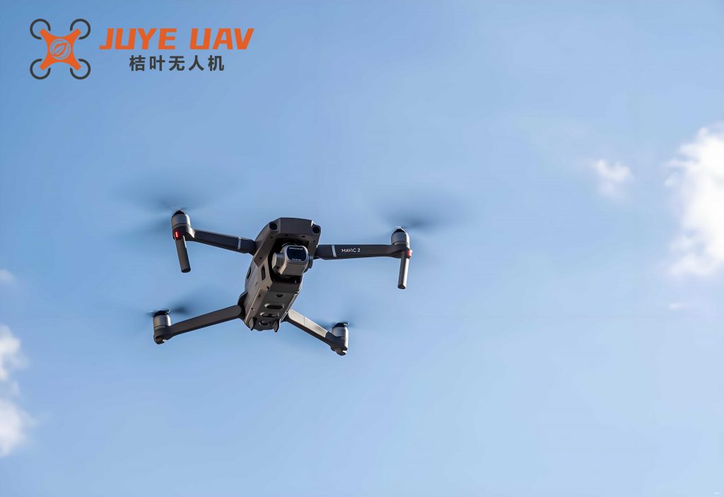
The hardware architecture of the autonomous quadrotor drone is designed for reliability, precision, and real-time performance. A modular approach ensures clear separation of concerns and simplifies debugging and testing. The core of the system is the flight controller unit (FCU).
| Module | Component/Model | Primary Function |
|---|---|---|
| Core Controller | Pixhawk-based FCU with STM32F427 (Main) & STM32F103 (Fail-safe) | Runs navigation, control algorithms, and manages all peripherals. Dual-processor for redundancy. |
| Inertial Measurement Unit (IMU) | L3GD20H (16-bit Gyro) & LSM303D (14-bit Accel/Mag) | Measures angular rates $$ (p, q, r) $$ and linear acceleration $$ (a_x, a_y, a_z) $$ for attitude estimation. |
| Barometric Pressure Sensor | MS5611 | Estimates altitude (z) by measuring atmospheric pressure changes. |
| Optical Flow & Sonar Module | MT9V034 Camera, L3GD20 Gyro, US-100 Ultrasonic | Provides velocity and position estimates via visual odometry ($$ \Delta x, \Delta y $$). Sonar gives precise height above ground (<5m). |
| Global Positioning System | U-Blox NEO-M8N | Provides global position (latitude, longitude) and velocity for outdoor navigation. |
| Power Management | Voltage Regulators, Current Sensors | Distributes power from Li-Po battery, monitors voltage/current for battery safety. |
| Actuation System | Brushless DC Motors (BLDC), Electronic Speed Controllers (ESC), Propellers | Converts PWM signals from FCU into rotational thrust. ESCs run closed-loop speed control. |
| Communication | Telemetry Radio (915MHz), RC Receiver | Enables ground station monitoring and provides manual override via RC transmitter. |
The selection of the STM32F427 as the main processor is pivotal. Its ARM Cortex-M4 core with a floating-point unit (FPU) running at 180 MHz provides the necessary computational power for sophisticated sensor fusion algorithms like complementary filters or Kalman filters in real-time. The rich set of peripherals (multiple timers for PWM generation, USART/SPI/I2C for sensor communication, DMA controllers) makes it exceptionally suitable for a quadrotor drone flight controller. The fail-safe co-processor (STM32F103) continuously monitors the main processor’s health and can trigger a stabilized landing procedure in case of a fault, enhancing the safety of the autonomous quadrotor drone.
The sensor fusion algorithm is critical for obtaining a reliable state estimate. The attitude (roll $$ \phi $$ and pitch $$ \theta $$) is primarily estimated by fusing accelerometer and gyroscope data. A complementary filter is used for its simplicity and effectiveness:
$$ \begin{align*}
\hat{\phi}_{\text{acc}} &= \arctan2(a_y, a_z) \\
\hat{\theta}_{\text{acc}} &= \arctan2(-a_x, \sqrt{a_y^2 + a_z^2}) \\
\hat{\phi} &= \alpha (\hat{\phi} + g_y \cdot \Delta t) + (1-\alpha) \hat{\phi}_{\text{acc}} \\
\hat{\theta} &= \alpha (\hat{\theta} + g_x \cdot \Delta t) + (1-\alpha) \hat{\theta}_{\text{acc}}
\end{align*} $$
Where $$ g_x, g_y $$ are gyroscope readings, $$ \Delta t $$ is the sampling period, and $$ \alpha $$ is a filter gain close to 1 (e.g., 0.98). Yaw ($$ \psi $$) is estimated by integrating the gyroscope’s z-axis reading, periodically corrected by the magnetometer heading.
For position and velocity estimation, a hierarchical approach is used. At high altitude (>5m), GPS and barometer data are fused. During low-altitude flight, landing, or in GPS-denied environments, the optical flow sensor combined with the ultrasonic rangefinder becomes the primary source for horizontal velocity ($$ v_x, v_y $$) and height above ground ($$ z_{\text{AGL}} $$). The state estimator seamlessly blends these data sources based on availability and reliability metrics.
The autonomous takeoff and landing logic is implemented using a cascaded PID control architecture. This structure consists of an outer loop for position/velocity control and an inner loop for attitude control. The inner loop runs at a much higher frequency (e.g., 500 Hz) to ensure stability, while the outer loop runs at a lower frequency (e.g., 100 Hz).
Control Law Formulation:
1. Position Controller (Outer Loop): Takes desired position $$ \mathbf{p}_d = [x_d, y_d, z_d]^T $$ and desired yaw $$ \psi_d $$ as input. Generates desired thrust $$ T_d $$ and desired roll/pitch angles $$ \phi_d, \theta_d $$.
$$ \begin{align*}
\mathbf{e}_p &= \mathbf{p}_d – \hat{\mathbf{p}} \\
\mathbf{v}_d &= \mathbf{K}_{p,p} \mathbf{e}_p + \mathbf{K}_{i,p} \int \mathbf{e}_p \, dt + \mathbf{K}_{d,p} \dot{\mathbf{e}}_p \quad \text{(PID)} \\
\phi_d &= \arcsin( \frac{m}{T} ( v_{d,x} \sin\hat{\psi} – v_{d,y} \cos\hat{\psi} ) ) \\
\theta_d &= \arcsin( \frac{m}{T} ( v_{d,x} \cos\hat{\psi} + v_{d,y} \sin\hat{\psi} ) ) \\
T_d &= \frac{m g – (m v_{d,z})}{\cos\hat{\phi} \cos\hat{\theta}} \quad \text{(Simplified, assuming small angles)}
\end{align*} $$
2. Attitude Controller (Inner Loop): Takes desired angles $$ (\phi_d, \theta_d, \psi_d) $$ and desired thrust $$ T_d $$. Generates desired control torques $$ \boldsymbol{\tau}_d $$.
$$ \begin{align*}
\mathbf{e}_\Theta &= [\phi_d – \hat{\phi}, \theta_d – \hat{\theta}, \psi_d – \hat{\psi}]^T \\
\boldsymbol{\tau}_d &= \mathbf{K}_{p,\Theta} \mathbf{e}_\Theta + \mathbf{K}_{i,\Theta} \int \mathbf{e}_\Theta \, dt + \mathbf{K}_{d,\Theta} \dot{\mathbf{e}}_\Theta \quad \text{(PID)}
\end{align*} $$
3. Control Allocation: Maps $$ [T_d, \boldsymbol{\tau}_d^T]^T $$ to desired motor squared speeds $$ \boldsymbol{\Omega}_d $$ by inverting the allocation matrix $$ \mathbf{B} $$ (using the pseudo-inverse $$ \mathbf{B}^+ $$).
$$ \boldsymbol{\Omega}_d = \mathbf{B}^+ \begin{bmatrix} T_d \\ \boldsymbol{\tau}_d \end{bmatrix} $$
The final PWM signals for each ESC are computed as $$ \text{PWM}_i = k \sqrt{\Omega_{d,i}} + \text{PWM}_{\text{min}} $$.
Autonomous Takeoff Sequence:
The takeoff procedure for the quadrotor drone is initiated by a ground command. The sequence is:
- Arming & Pre-check: The system checks IMU calibration, sensor status, and battery level. Motors start spinning at a minimal “idle” speed.
- Ascension Phase: The position controller’s setpoint is set to $$ \mathbf{p}_d(t) = [0, 0, z_{\text{takeoff}}]^T, \psi_d=0 $$, where $$ z_{\text{takeoff}} $$ is a predefined safe altitude (e.g., 2 meters). The controller commands a smooth increase in collective thrust, transitioning through vertical velocity control to reach the target altitude.
- Stabilization: Upon reaching $$ z_{\text{takeoff}} $$, the quadrotor drone enters a stabilized hover, waiting for the next navigation command. During this phase, the optical flow sensor is activated to maintain precise position hold, especially in low-altitude or indoor environments.
Autonomous Landing Sequence:
The landing procedure is more critical as it involves ground detection and gentle touchdown.
- Descent Initiation: The target position is set to the home location or a specified landing pad: $$ \mathbf{p}_d = [x_{\text{home}}, y_{\text{home}}, z_{\text{land}}]^T $$. Initially, $$ z_{\text{land}} $$ is set to a few meters above ground.
- Approach Phase: The quadrotor drone navigates to the point above the landing target using its position controller.
- Final Descent: Once positioned, $$ z_{\text{land}} $$ is gradually decreased at a constant, low descent rate (e.g., 0.3 m/s). The ultrasonic sensor provides the critical height-above-ground measurement $$ z_{\text{AGL}} $$ for this phase, overriding the barometer which is prone to ground effect disturbances.
- Touchdown Detection & Motor Cutoff: When $$ z_{\text{AGL}} $$ falls below a very low threshold (e.g., 0.1m) and the vertical velocity is near zero, a “landed” state is triggered. The flight controller commands all motors to stop after a brief delay, completing the autonomous landing cycle for the quadrotor drone.
The software architecture is built on a real-time operating system (FreeRTOS) to manage concurrent tasks efficiently. The main tasks and their priorities are outlined below:
| Task Name | Priority | Frequency (Hz) | Key Functions |
|---|---|---|---|
| Sensor Data Acquisition | High | 1000 | Reads IMU, Baro, Sonar via SPI/I2C; Timestamping. |
| State Estimation | High | 500 | Runs attitude filter, position/velocity fusion. |
| Attitude Control | Highest | 500 | Inner-loop PID, computes $$ \boldsymbol{\tau}_d $$. |
| Position Control | Medium-High | 100 | Outer-loop PID, computes $$ T_d, \phi_d, \theta_d $$. |
| Motor Mixing & Output | Highest | 500 | Control allocation, PWM signal update to ESCs. |
| Communication | Low | 50 | Handles telemetry downlink and RC command parsing. |
| Navigation & Mission | Low | 10 | Executes flight plan (e.g., takeoff, waypoints, land). |
The core control flow is interrupt-driven for precise timing. A high-rate timer interrupt triggers the attitude control and motor output tasks, ensuring deterministic loop timing, which is crucial for the stability of the quadrotor drone.
The performance of the autonomous quadrotor drone system was evaluated through a series of flight tests. The key metrics were takeoff consistency, hover position hold accuracy, and landing precision and reliability.
| Test Phase | Metric | Outdoor (GPS+Flow) | Indoor (Flow Only) |
|---|---|---|---|
| Takeoff & Hover | Altitude Hold RMSE | ±0.15 m | ±0.08 m |
| Position Hold RMSE (XY) | ±0.25 m | ±0.10 m | |
| Landing | Final Touchdown XY Error | ±0.35 m | ±0.15 m |
| Descent Rate at Touchdown | < 0.4 m/s | < 0.3 m/s | |
| Success Rate | 95% | 100% |
The results demonstrate that the designed system meets the requirements for safe autonomous operation. The indoor performance is superior due to the high precision of the optical flow sensor in environments with adequate visual texture. The cascaded PID controller provided stable and responsive control for the quadrotor drone. The integration of the ultrasonic sensor for the final landing phase proved essential for a gentle and consistent touchdown, preventing bounce or tip-over.
In conclusion, this work successfully detailed the complete design and implementation of an autonomous flight control system for a quadrotor drone, with specialized algorithms for takeoff and landing. The hardware centered around the powerful and reliable STM32 microcontroller provides a robust platform. The software employs a cascaded control structure with multi-sensor fusion, enabling the quadrotor drone to perform autonomous missions reliably. The proposed strategies for takeoff and landing, leveraging height sensors and velocity control, effectively minimize human error and operational risks. Future work will focus on integrating more advanced control techniques like model predictive control (MPC) to handle aggressive maneuvers and external disturbances better, and on implementing machine learning for terrain-aware landing on uneven surfaces. The modularity of the system also allows for the straightforward addition of payloads like robotic arms or specialized sensors, expanding the utility of the autonomous quadrotor drone platform.