
Addressing the prevalent challenges in modern precision agriculture, including non-uniform spraying, significant droplet drift, low effective utilization rates of agrochemicals, and consequent environmental pollution associated with UAV drone operations, this research presents the design and experimental validation of an intelligent, adaptive spraying system. This UAV drone-based system is engineered to perform variable-angle and variable-rate spraying by dynamically recognizing the spatial structure of fruit tree canopies during flight operations.
The core innovation lies in the integration of real-time machine vision for canopy dimensioning with a closed-loop electromechanical control system. A downward-facing camera mounted on the UAV drone captures continuous imagery of the orchard rows below. These images are processed by an onboard Jetson Orin Nano computing module, which executes a custom algorithm combining Region of Interest (ROI) selection and a sub-interval line scanning method. This algorithm accurately identifies the lateral boundaries of the fruit tree canopy and calculates the pixel-based width of the tree row. The extracted parameters—specifically, the canopy boundary coordinates and the canopy coverage ratio within the field of view—are transmitted to a dedicated STM32 microcontroller. The boundary information is used to compute and command the necessary adjustment to the spray nozzle angle, while the coverage ratio informs the required liquid flow rate. The system implements a dual closed-loop control scheme: one loop regulates the nozzle’s angular position via a stepper motor with magnetic encoder feedback, and the other loop controls the liquid flow via a brushless pump with an inline flow meter. A Fuzzy PID controller is employed to enhance the responsiveness and stability of both control loops. Experimental validation confirms the system’s capability to significantly reduce off-target deposition and improve spray uniformity, thereby offering a practical solution for enhancing the precision and sustainability of UAV drone-based orchard spraying.
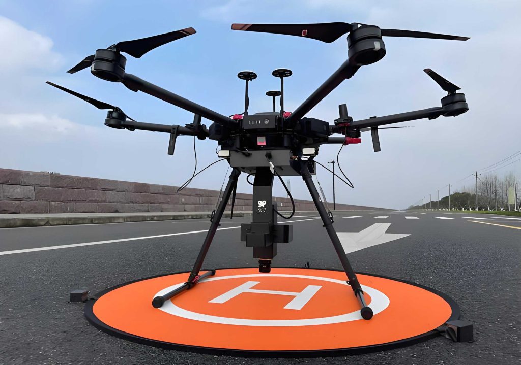
1. System Design for UAV Drone-Based Adaptive Spraying
The proposed system is architected as a modular add-on for a standard multi-rotor UAV drone platform. Its primary function is to modulate the spray pattern in real-time to match the cross-sectional profile and density of the underlying tree row, moving beyond the fixed, blanket-coverage approach of conventional UAV drone sprayers.
1.1 Mechanical and Hardware Configuration
The physical apparatus is mounted beneath the UAV drone’s fuselage, centered along its flight path. It comprises several key components selected for their performance, reliability, and suitability for airborne operation. The major hardware elements and their specifications are summarized in Table 1.
| Component | Model | Key Parameters |
|---|---|---|
| Vision Sensor | Gemini 335L Camera | IP65, Resolution: 1280×800, Frame Rate: 60 fps |
| Processing Unit | Jetson Orin Nano | AI Performance: 70 TOPS, Memory: 8 GB |
| Main Controller | STM32F407VET6 MCU | Core: ARM Cortex-M4, Clock: 168 MHz |
| Angle Adjustment Actuator | 17HS15-0404S Stepper Motor | Step Angle: 1.8°, Holding Torque: 0.45 Nm |
| Angle Feedback | AS5600 Magnetic Encoder | Interface: I²C, Range: 0-360° |
| Liquid Pump | TL-B04 Brushless Pump | Max Flow: 4.2 L/min, Max Head: 1.2 m |
| Flow Control Module | YF-44 PWM Driver | Input: 24V, PWM Frequency: 0-10 kHz |
| Flow Measurement | YF-S201 Hall Effect Flow Meter | Working Pressure: ≤1.75 MPa, Pulse Ratio: 5880 pulses/L |
| Spray Nozzle | Hollow Cone Nozzle | Orifice Diameter: 0.8 mm, Spray Angle (static): 80° |
The camera, fixed on a vibration-damped bracket, provides the visual input. The nozzle is mounted on a rotating platform driven by the stepper motor, allowing its spray angle to be pivoted laterally. The pump draws liquid from the UAV drone’s tank and delivers it to the nozzle via the flow meter. The entire control logic is orchestrated by the STM32, which receives high-level commands from the Jetson Nano and executes low-level motor and pump control.
1.2 System Workflow and Control Logic
The operational sequence is cyclical, synchronized with the UAV drone’s forward motion. The workflow, illustrated in the conceptual diagram, follows these steps:
- Image Acquisition & Processing: The camera captures an image of the scene directly ahead of the spray swath. The Jetson Nano processes this image to identify the left (L_i) and right (R_i) boundaries of the tree canopy and calculates the canopy coverage ratio (C_i) for the imminent spray zone.
- Command Generation: Based on the canopy width (R_i – L_i), the desired spray angle (θ_target) is calculated. Based on C_i and the UAV drone’s ground speed, the target flow rate (Q_target) is determined. These setpoints, along with a timing parameter, are sent to the STM32.
- Closed-Loop Actuation: The STM32 generates control signals.
- For angle control: It drives the stepper motor to achieve θ_target. The AS5600 encoder provides real-time angular position feedback (θ_feedback).
- For flow control: It outputs a PWM signal to the pump driver to achieve Q_target. The YF-S201 flow meter provides real-time flow rate feedback (Q_feedback).
- Fuzzy PID Regulation: Both control loops utilize Fuzzy PID algorithms. The error (e) and rate of change of error (ec) for angle and flow are fuzzified. The fuzzy inference engine applies rule bases (like the one partially shown in Table 2) to dynamically adjust the PID gains (Kp, Ki, Kd), optimizing the response for nonlinearities and varying load conditions inherent in a flying UAV drone system.
The calculation for the spray angle adjustment is geometrically derived. Let W_target be the recognized canopy width at flight height H. The required angular deviation Δθ from the default centered position (θ_0) to cover from left to right boundary is:
$$ \Delta\theta = \arctan\left(\frac{W_{\text{target}}}{2H}\right) – \arctan\left(\frac{W_0}{2H}\right) $$
Where W_0 is the width covered by the default fixed spray angle. The motor is commanded to rotate by Δθ.
| ΔKp | Error Change Rate (EC) | ||||||
|---|---|---|---|---|---|---|---|
| NB | NM | NS | ZO | PS | PM | PB | |
| NB | PB | PB | PM | PM | PS | ZO | ZO |
| NM | PB | PB | PM | PS | PS | ZO | NS |
| NS | PM | PM | PM | PS | ZO | NS | NS |
| ZO | PM | PM | PS | ZO | NS | NM | NM |
| PS | PS | PS | ZO | NS | NS | NM | NM |
| PM | PS | ZO | NS | NM | NM | NM | NB |
| PB | ZO | ZO | NM | NM | NM | NB | NB |
Note: NB=Negative Big, NM=Negative Medium, NS=Negative Small, ZO=Zero, PS=Positive Small, PM=Positive Medium, PB=Positive Big. Similar rule tables are defined for ΔKi and ΔKd.
1.3 Control System Modeling and Simulation
The dynamics of the actuation systems were modeled to design the controllers. The stepper motor with its load is approximated as a second-order system. The transfer function G_1(s) between input voltage V(s) and angular position θ(s) is:
$$ G_1(s) = \frac{\theta(s)}{V(s)} = \frac{K}{s[(Ls+R)(Js+B) + K^2]} $$
Where K is the motor torque constant, L and R are winding inductance and resistance, J is the total inertia, and B is the viscous damping coefficient. With identified parameters, the simplified model is:
$$ G_1(s) = \frac{316.67}{0.00008s^2 + 0.000752s + 1} $$
The pump-flow meter system is modeled with a higher-order transfer function G_2(s):
$$ G_2(s) = \frac{0.05}{1.93\times10^{-8}s^3 + 7.24\times10^{-6}s^2 + 0.0025s} $$
Simulations comparing traditional PID and Fuzzy PID controllers were conducted in MATLAB/Simulink. The Fuzzy PID controller demonstrated superior performance: it reduced overshoot from 20-25% to less than 5%, shortened settling time from 0.6s to approximately 0.3s, and eliminated steady-state oscillation, proving its robustness for the UAV drone application.
2. Canopy Recognition and Measurement Algorithm
The efficacy of the entire UAV drone system hinges on the accurate, real-time identification of tree canopy dimensions. The algorithm must be computationally efficient to run on the embedded Jetson platform and robust to varying lighting and background conditions.
2.1 Image Pre-processing Pipeline
Images are acquired at a 30-degree gimbal angle during UAV drone flight. The pre-processing stages are:
- Median Filtering: A 3×3 median filter is applied to suppress salt-and-pepper noise while preserving edge integrity, which is crucial for subsequent boundary detection.
- Background Segmentation: The green canopy is separated from the background (soil, grass, sky). Otsu’s automatic thresholding method was selected after comparative analysis (Table 3) for its optimal balance between segmentation accuracy and computational speed, a critical factor for real-time operation on a UAV drone.
- Adaptive ROI Selection: To minimize processing time, a Region of Interest is dynamically defined. A vertical scanline (1-pixel wide, 60-pixel tall) centered on the image column is swept horizontally. The leftmost and rightmost columns where white (plant) pixels are detected define the initial rough ROI boundaries, which are then expanded outward by a fixed margin to ensure the entire tree row is encompassed.
| Method | Segmentation Quality | Processing Time (ms) | Suitability for UAV Drone |
|---|---|---|---|
| Otsu’s Method | High | ~0.34 | Excellent (Fast & Accurate) |
| Fixed Threshold | Medium | ~1.0 | Good |
| K-means Clustering (K=2) | Medium-Low | ~198.3 | Poor (Too Slow) |
| GrabCut Algorithm | High | >23000 | Unsuitable (Extremely Slow) |
2.2 Sub-interval Line Scanning and Boundary Detection
Within the defined ROI, the algorithm divides the image vertically into N horizontal sub-intervals (e.g., N=9). For each sub-interval:
- Column-wise Pixel Summation: For each column x within the ROI width, the number of white pixels W(x) in that sub-interval is summed.
- Temporal Local Difference (TL) Calculation: A discrete derivative is computed to highlight edges:
$$ TL(x) = W(x) – W(x-1) $$
A large positive TL indicates a transition from background to canopy (left edge), while a large negative TL indicates a transition from canopy to background (right edge). - Boundary Point Identification: A Temporal Variation (TV) sequence is created:
$$ TV(x) = \begin{cases} 1, & \text{if } TL(x) = 0 \\ 0, & \text{if } TL(x) \neq 0 \end{cases} $$
Continuous runs of TV=1 represent the interior of the canopy. The left boundary point for the sub-interval is the first transition from 1 to 0 on the left side, and the right boundary point is the start of the longest run of TV=1 from the right side.
2.3 Boundary Fitting and Real-world Calibration
The detected boundary points from all sub-intervals are often discrete and noisy. A linear least-squares fitting is applied separately to the set of left points and right points to obtain smooth, continuous boundary lines defined by equations y = m_left * x + c_left and y = m_right * x + c_right.
To convert pixel measurements to real-world dimensions (meters), the camera was calibrated using Zhang’s method. The camera intrinsic matrix K_c and distortion coefficients were obtained:
$$ K_c = \begin{bmatrix} 1125.09 & 0 & 594.85 \\ 0 & 1124.52 & 368.83 \\ 0 & 0 & 1 \end{bmatrix} $$
Using the known flight height H and the camera’s projective geometry, the pixel width between the fitted boundaries at the image row corresponding to the UAV drone’s nadir is converted to real canopy width W_target. The offline recognition rate for canopy boundaries was 91.58%, and the average processing time per frame was 158 ms, validating its feasibility for real-time use on a UAV drone.
3. Bench Test and Experimental Validation
A comprehensive bench test platform was established to evaluate the performance of the UAV drone spraying system’s components and control logic under controlled conditions before field deployment.
3.1 Test Platform Setup
The platform simulated a UAV drone hovering over a target. Potted trees were arranged to form rows of varying widths. The spraying device was mounted on a fixed gantry at a height of 2 meters. Water-sensitive papers (WSP) were placed on the ground within the target area (canopy row) and in the off-target area (between rows) to collect droplet deposition data. The system’s computer (Jetson Nano + STM32) was stationed nearby, connected to the actuators and sensors.
3.2 Canopy Width Recognition Accuracy
The vision algorithm’s accuracy was tested by comparing its recognized canopy width against manually measured ground truth widths for 15 different row configurations. The results, summarized in Table 4, show a strong linear correlation (R² = 0.91) between measured and detected widths. The mean absolute error was 7.32%, with a maximum error of 8.62%, confirming the algorithm’s reliability for informing the UAV drone’s spray control system.
| Test No. | Ground Truth Width (cm) | Detected Width (cm) | Absolute Error (%) |
|---|---|---|---|
| 1 | 80.0 | 73.1 | 8.62 |
| 2 | 95.0 | 88.4 | 6.95 |
| 3 | 110.0 | 103.9 | 5.55 |
| … | … | … | … |
| 15 | 150.0 | 161.3 | 7.53 |
| Mean Absolute Error | 7.32% | ||
| Linear Fit R² | 0.91 | ||
3.3 Spray Deposition Effectiveness
The core functionality of the UAV drone system—adaptive spraying—was tested under two canonical scenarios:
Scenario A (Wide Fixed Spray, Narrow Target): The default fixed nozzle angle was set to cover an area wider than the tree row. The system was tested in “OFF” (fixed angle) and “ON” (adaptive angle) modes. With adaptation, the nozzle angle was reduced to match the narrower row.
Scenario B (Narrow Fixed Spray, Wide Target): The default angle was set narrower than the tree row. In adaptive mode, the nozzle angle increased to cover the full width.
Deposition data from WSPs was analyzed using DepositScan software. Key results are in Table 5. The adaptive system dramatically reduced off-target deposition in Scenario A (by 51.94% on average) and increased on-target deposition in Scenario B (by 54.8% on average). The distribution uniformity, assessed via kernel density estimation plots, was also significantly improved when the system was active, showing a smoother, more concentrated distribution of droplet densities compared to the fixed-spray mode’s scattered and multi-peak distribution.
| Scenario | System Mode | Avg. Droplet Density in Target Zone (drops/cm²) | Avg. Droplet Density in Off-Target Zone (drops/cm²) | Change vs. Fixed Mode |
|---|---|---|---|---|
| A: Wide Spray on Narrow Target | Fixed Angle (OFF) | 98.7 | 51.2 | Baseline |
| Variable Angle (ON) | 102.5 | 24.6 | Off-target ↓ 51.94% | |
| B: Narrow Spray on Wide Target | Fixed Angle (OFF) | 46.3 | 2.1 | Baseline |
| Variable Angle (ON) | 71.7 | 4.8 | On-target ↑ 54.8% |
3.4 Flow Control Accuracy Validation
The precision of the variable-rate component was tested by commanding three specific flow rates and measuring the actual output volumetrically. Each setpoint was tested three times. The Fuzzy PID controller demonstrated excellent tracking performance, with an average error of 1.50%, outperforming a standard PID controller which had an average error of 1.82% under the same conditions. This high accuracy is essential for the UAV drone to correctly meter agrochemicals based on canopy density.
3.5 Preliminary Field Trial
A single-factor comparative field trial was conducted in an orchard. The UAV drone flew over tree rows at a constant speed and height. The only variable was the state of the adaptive system (ON vs. OFF). WSPs were placed at different canopy levels. An independent samples t-test on the average droplet deposit data from multiple trees showed a statistically significant difference (t-statistic = 3.29, p-value = 0.03 < 0.05). This confirms that activating the adaptive system on the UAV drone leads to a quantitatively better deposition outcome under real-world conditions.
4. Conclusion
This research successfully designed, implemented, and validated an intelligent variable-angle and variable-rate spraying device for UAV drone application in orchard environments. The system integrates a fast and robust machine vision algorithm for real-time canopy boundary and width recognition with a responsive dual-loop Fuzzy PID control system for actuating the spray nozzle and pump.
The key outcomes are:
- Effective System Design: A practical hardware and control architecture was developed, enabling a UAV drone to dynamically adjust its spray pattern based on instantaneous canopy geometry.
- Accurate Canopy Recognition: The proposed image processing algorithm achieved an offline recognition rate of 91.58% and a mean width detection error of 7.32%, proving sufficient for real-time control of the UAV drone sprayer.
- Significant Performance Improvement: Bench tests demonstrated the system’s capability to reduce off-target deposition by over 51% when the default spray was too wide, and increase on-target deposition by over 54% when the default spray was too narrow. This directly translates to reduced chemical waste, lower environmental impact, and improved efficacy for the UAV drone operation.
- Enhanced Control Precision: The use of Fuzzy PID control ensured stable and accurate positioning and flow regulation, with flow rate errors below 1.5%.
The field trial provided preliminary evidence of the system’s effectiveness in an authentic orchard setting. In conclusion, this UAV drone-based adaptive spraying system represents a significant step towards true precision aerial application in horticulture. By ensuring that spray is delivered only where it is needed and at an appropriate intensity, it enhances the sustainability, economy, and safety of UAV drone-mediated crop protection.