
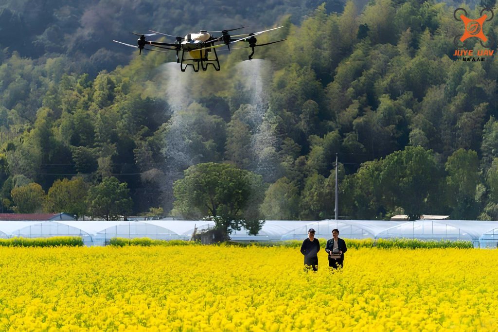
The effective and precise application of agrochemicals is a cornerstone of modern agriculture, essential for protecting crop yields from pests and diseases. Traditional ground-based spraying methods often suffer from inefficiencies, uneven coverage, and high operator exposure risks, particularly in challenging terrain. The advent of Unmanned Aerial Vehicles (UAVs) has opened a new frontier for precision agriculture. An agricultural UAV, or crop protection drone, offers a versatile platform capable of reaching difficult areas, applying treatments uniformly, and significantly reducing chemical usage and environmental impact. However, the full potential of an agricultural UAV is unlocked only when paired with an intelligent, reliable, and precise spraying control system. This article details the first-person design, implementation, and testing of a comprehensive spraying control system built around the STC89C52 microcontroller, developed to enhance the operational precision and digital management of agricultural UAV spraying missions.
1. System Architecture and Overview
The designed precision spraying system is an integrated solution comprising three main subsystems: the Spray Execution System, the On-board Control Hardware/Software, and the Ground-based Remote Control Hardware/Software. The system architecture is built upon a hexacopter agricultural UAV platform, which provides stable flight and adequate payload capacity. The core philosophy is to enable variable-rate application, real-time monitoring, and remote parameter adjustment, transforming the agricultural UAV from a simple carrier into a smart application tool.
The Spray Execution System handles the physical delivery of the liquid agent. The On-board Control System, centered on an STC89C52 MCU, is responsible for sensor data acquisition, actuator control, and communication with the ground station. The Ground Control System features a Human-Machine Interface (HMI) touchscreen, allowing the operator to monitor all spraying parameters in real-time and send control commands wirelessly. Data flows bi-directionally via a robust NRF24L01+ wireless link, creating a closed-loop control system for the agricultural UAV.
2. Hardware Design of the Spray Control System
The hardware design is segmented into the airborne unit and the ground control unit, each serving distinct but interconnected roles in managing the agricultural UAV‘s spraying functions.
2.1 On-board Control Hardware
The heart of the on-board system is the STC89C52RD2 microcontroller, a low-power, high-performance CMOS 8-bit controller from STC Micro. Its role is to orchestrate all data collection and actuator control processes on the agricultural UAV.
- Sensor Interface Modules:
- PCF8591 AD/DA Converter: This I²C-based module acquires analog voltage signals from the pressure sensor and liquid level sensor, converting them into digital values for the MCU.
- LM393 Comparator Module: It conditions the pulse signal from the Hall-effect flow sensor, providing a clean, TTL-compatible digital pulse train to the MCU’s counter input for flow rate calculation.
- Actuator Driver: A dedicated PWM DC motor driver module based on power MOSFETs receives control signals from the MCU. It drives the diaphragm pump motor, allowing for precise speed (and thus pressure/flow) control through PWM duty cycle adjustment. It includes protective features like TVS diodes for handling back EMF from the motor.
- Wireless Communication: The NRF24L01+ 2.4GHz transceiver module manages all communication with the ground station. It is configured for enhanced shockburst protocol, ensuring reliable and low-latency data packet exchange for the agricultural UAV system.
- Power Supply: A regulated power board provides stable +5V and +3.3V rails from the UAV’s main battery (typically 12V) for the MCU, sensors, and wireless module.
2.2 Spray Execution Hardware
This subsystem comprises the physical components attached to the agricultural UAV frame that perform the spraying action.
- Diaphragm Pump (LS-1416): Selected for its chemical resistance and reliable performance. It provides a maximum pressure of 0.5 MPa and a flow rate of 5.0 L/min at 12V.
- Spray Nozzles: TeeJet TTI110015 air induction flat fan nozzles were chosen. They produce a uniform spray pattern with larger, air-entrained droplets that reduce drift, a critical factor for agricultural UAV applications.
- Sensors:
- Flow Sensor: OKD-HZ41CF Hall-effect sensor, generating pulses proportional to flow volume (approx. 4000 pulses/liter).
- Pressure Sensor: MIK-P300 with a 0-0.6 MPa range and 1-5V analog output.
- Liquid Level Sensor: A5-150 float-type sensor with analog voltage output, resistant to agrochemicals.
- Liquid Tank & Manifold: A 10L chemically resistant polypropylene tank with an integrated level sensor port. The fluid circuit includes tubing, a filter, and a manifold to distribute liquid to the four nozzles.
2.3 Ground Control Hardware
The ground station provides the operator interface. Its core is another STC89C52 MCU, which communicates with a 7-inch TJC8048K070 resistive touchscreen HMI via UART. The MCU also hosts an NRF24L01+ module identical to the airborne unit, establishing a peer-to-peer wireless link. The HMI is the central console for monitoring and commanding the agricultural UAV‘s spray system.
| Subsystem | Component | Model/Specification | Key Function |
|---|---|---|---|
| On-board Control | Microcontroller | STC89C52RD2 | System control & data processing |
| Wireless Module | NRF24L01+ | 2.4GHz bi-directional data link | |
| Motor Driver | YC-MD1301-2 | PWM control of 12V pump motor | |
| Spray Execution | Diaphragm Pump | LS-1416 | Generates spray pressure (0.5 MPa max) |
| Nozzles (x4) | TeeJet TTI110015 | Produces uniform, low-drift spray pattern | |
| Flow Sensor | OKD-HZ41CF | Measures liquid flow rate (0.3-6 L/min) | |
| Pressure Sensor | MIK-P300-0.6MPa | Measures line pressure (0-0.6 MPa) | |
| Ground Control | HMI Touchscreen | TJC8048K070 (7″) | Real-time display and operator input |
3. Software and Algorithm Design
The system’s intelligence is embedded in the software running on both the airborne and ground MCUs. The code was developed in C using the Keil µVision IDE.
3.1 On-board Control Software Flow
The software on the agricultural UAV follows a structured loop to manage spraying operations autonomously based on commands and sensor feedback.
- Initialization: Configures I/O ports, timers, counters, the I²C bus for the PCF8591, and the SPI bus for the NRF24L01+. Initial parameters are set.
- Sensor Data Acquisition & Processing:
- Calls an I²C subroutine to read the PCF8591, obtaining digitized values for pressure and liquid level.
- Reads the timer/counter register to get the pulse count from the flow sensor over a fixed interval (e.g., 100ms). The instantaneous flow rate \( Q_{inst} \) is calculated as:
$$ Q_{inst} = \frac{PulseCount}{K_{sensor} \times \Delta t} $$
where \( K_{sensor} \) is the sensor’s calibration constant (pulses/liter) and \( \Delta t \) is the sample time. Cumulative volume \( V_{total} \) is updated:
$$ V_{total}(n) = V_{total}(n-1) + \frac{PulseCount}{K_{sensor}} $$
- Wireless Communication:
- Data Transmission: Packages sensor data (pressure, flow, level, system voltage) into a defined protocol frame and transmits it to the ground station via the NRF24L01+.
- Command Reception: Listens for incoming packets from the ground. These packets contain the desired Pump PWM duty cycle and On/Off command.
- Actuator Control: Extracts the PWM setpoint from the received command and writes it to the timer register controlling the pump driver. This adjusts the pump speed and thus the system pressure. A simple control logic can be implemented, such as:
$$ PWM_{output} = f(P_{target}, P_{measured}) $$
For initial testing, open-loop control based on the ground command was used.
3.2 Ground Control Software & HMI Design
The ground software focuses on communication and the user interface. It initializes the UART for the HMI and the wireless module. Its main loop:
- Receives telemetry data packets from the agricultural UAV.
- Formats this data and sends it via UART to the HMI for display.
- Polls the HMI for any user input (e.g., touch events on buttons or sliders).
- Packages these control commands and wirelessly transmits them to the agricultural UAV.
The HMI was designed using dedicated software (like USART HMI) to create multiple interactive pages:
- Login Page: Secured access with a password.
- Main Dashboard (Parameter Display): Shows all critical real-time data using both numerical displays and analog-style gauges for pressure, flow rate, liquid level, pump voltage/current, and environmental temperature/humidity (from an optional DHT11 sensor).
- Status Display Page: Presents data with graphical elements (e.g., a filling tank for level). It houses virtual buttons for Pump Start/Stop and a slider or input box for setting the PWM duty cycle (0-100%).
- Data Logging/Curve Pages: For plotting parameter trends over time.
- Configuration Page: For setting wireless channel, addresses, and other system parameters.
3.3 Data Communication Protocol
A compact, efficient packet structure was defined for the NRF24L01+ link to ensure reliable data exchange for the agricultural UAV system. Each packet contains specific bytes for:
- Packet Header (Sync bytes)
- Address and Command Type
- Data Payload (e.g., Pressure_H, Pressure_L, Flow_H, Flow_L, Level, PWM_Command, Pump_Status_Flag)
- Checksum (for error detection)
The software implements automatic acknowledgment (Auto-Ack) and retransmission logic provided by the NRF24L01+ Enhanced ShockBurst™ to enhance link reliability.
| Page Name | Display Elements | Control Elements | Primary Purpose |
|---|---|---|---|
| Dashboard | Numerical values, analog gauges for Pressure, Flow, Level, Voltage, Temperature, Humidity. | None (Read-only monitoring). | Real-time, glanceable overview of all agricultural UAV spray system parameters. |
| Status & Control | Graphical tank level, large numeric readouts, communication status LEDs. | Start/Stop Buttons, PWM Duty Cycle Slider (0-100%). | Primary page for interactive control of the spraying operation. |
| Data Trends | Time-series plots of Pressure, Flow, etc. | Clear/Reset graph buttons. | Post-mission analysis and system performance review. |
4. System Integration, Testing, and Performance
Following individual module tests, the complete system was integrated and subjected to rigorous bench testing and field trials.
4.1 Hardware and Software Debugging
Each hardware module was tested independently: sensor outputs were verified with calibrated instruments, the PWM driver was tested with the pump, and the wireless link’s range and stability were assessed. Software debugging involved verifying data acquisition accuracy, control loop timing, and the integrity of the wireless protocol. Sensor calibration coefficients \( K_{sensor} \) were determined empirically and stored in the MCU’s code memory.
4.2 Integrated System Testing
The full system was tested on a grounded agricultural UAV platform. Key relationships between control input and system output were characterized. For example, by varying the PWM duty cycle command \( D \) from the ground station, the resulting pump pressure \( P \), system current \( I \), and flow rate \( Q \) were measured.
| PWM Duty Cycle (%) | Pump Input Voltage (V, approx.) | System Current (A) | Line Pressure (MPa) | Total Flow Rate (L/min) | Estimated Field Work Rate* (ha/h) |
|---|---|---|---|---|---|
| 40 | 4.8 | 1.2 | 0.08 | 0.8 | 3.2 |
| 60 | 7.2 | 2.5 | 0.14 | 1.4 | 5.6 |
| 80 | 9.6 | 3.8 | 0.22 | 2.1 | 8.4 |
| 100 | 12.0 | 5.0 | 0.30 | 2.8 | 11.2 |
| *Estimation based on a 4.8m swath, 3.24 m/s (11.7 km/h) flight speed, and 1.0 L/ha application rate. | |||||
The data shows a strong correlation, allowing for predictable control. The pressure \( P \) as a function of PWM duty cycle \( D \) can be approximated linearly in the operating range:
$$ P \approx k \cdot D + c $$
where \( k \) and \( c \) are system-dependent constants derived from calibration.
4.3 Field Validation and Results
Operational tests confirmed the system’s functionality. The HMI successfully displayed all parameters in real-time with minimal latency (< 200ms). Commands from the ground were executed reliably by the agricultural UAV. The wireless link remained stable at operational distances exceeding 500 meters in open field conditions. The system demonstrated the key features of a precision agricultural UAV spray system:
- Digital Monitoring: All operational parameters (pressure, flow, volume, level) were quantified and displayed.
- Precision Control: The spray application rate could be varied precisely by adjusting the PWM setpoint based on the UAV’s flight speed and desired volume rate, moving towards true variable-rate application.
- Operational Efficiency: The intuitive HMI and reliable control reduced operator workload and increased situational awareness.
5. Conclusion
The design and implementation of this STC89C52-based spraying control system successfully addressed the need for precision and digital management in agricultural UAV operations. The system integrates reliable hardware components with structured software to achieve real-time monitoring, bi-directional wireless control, and variable application capability. Testing validated that the system operates stably, provides clear and intuitive feedback to the operator via the HMI, and allows for convenient parameter adjustment. This control system enhances the functionality of an agricultural UAV, transforming it into a more effective and intelligent tool for modern crop protection. Future work will focus on integrating GPS data for map-based variable rate control, implementing more advanced closed-loop pressure control algorithms, and testing droplet deposition quality under various flight and operational parameters.