We present a comprehensive design analysis of a bio-inspired butterfly drone, addressing the critical challenges of miniaturization in flapping-wing aerial vehicles: excessive mass and insufficient flight power. Our butterfly drone employs a dual-servo direct-drive mechanism, eliminating the need for complex mechanical transmissions. The airframe and wing skeletons are fabricated from high-strength, lightweight carbon fiber, achieving a total mass of only 37.5 g. The flight control system is built around an STM32F103C8T6 microcontroller, integrating a Bluetooth module for wireless communication with a ground station and an MPU6050 gyroscope for real-time attitude stabilization. Extensive simulation and physical testing demonstrate that our butterfly drone can achieve stable forward flight, turning maneuvers, and reliable wireless control at distances up to 9 m. This study provides a viable pathway for the miniaturization of flapping-wing robots.
Introduction
The development of bio-inspired flapping-wing aerial vehicles has gained significant attention due to their unique advantages over fixed-wing and rotary-wing platforms, including high aerodynamic efficiency, superior maneuverability, and stealth capabilities. However, scaling down these designs to the insect scale introduces severe trade-offs between structural integrity, actuation power, and weight. Existing micro aerial vehicles often suffer from insufficient lift generation because the wing area decreases quadratically while mass scales cubically with linear dimensions. This fundamental challenge motivated us to design a butterfly drone that mimics the flight mechanics of real butterflies, leveraging their characteristic clap-and-fling mechanism and passive wing deformation. By using direct servo actuation and optimizing the structural layout, we aimed to create a lightweight yet robust platform capable of autonomous flight.
Previous work on butterfly drones, such as the eMotionButterfly developed by Festo, demonstrated the feasibility of collective flight and obstacle avoidance. However, their design weighs over 90 g, limiting its application in confined environments. Our objective was to reduce the mass to below 40 g while maintaining adequate flight performance. The dual-servo architecture allows independent control of left and right wing pairs, enabling differential thrust for yaw maneuvers. The butterfly drone’s wings are constructed from carbon fiber rods and PC31n umbrella fabric, which provides excellent rigidity and tear resistance. The fuselage incorporates a silicone rubber tube that introduces passive fuselage oscillation, mimicking the body heave observed in real butterflies during flight—a key factor in enhancing lift via vortex ring formation.
In the following sections, we detail the structural design, control system architecture, and experimental validation of our butterfly drone. We emphasize the use of analytical models and experimental data to characterize its flight dynamics. The core metrics—mass distribution, wing kinematics, and control bandwidth—are summarized in tables and derived formulas to provide a quantitative framework for future optimizations.
Structural Design
The butterfly drone’s airframe is built around a 3D-printed servo bracket made of carbon fiber-reinforced polymer. Two KST X80plus micro servos are mounted symmetrically on this bracket. A 3 mm diameter carbon rod (length 10 mm) is inserted into the bracket’s central hole, serving as the main attachment point for the rear fuselage. To introduce passive body oscillation, a silicone rubber tube (outer diameter 4 mm, inner diameter 2 mm, length 20 mm) connects this rod to a second carbon rod (length 80 mm) that carries the flight control board and battery. This compliant joint allows the rear body to heave relative to the wing root, enhancing lift production as predicted by computational fluid dynamics studies on butterfly flight.
The wing assembly comprises a forewing and a hindwing connected by 3D-printed joints (Connector 1 and Connector 4). The wing venation is constructed from 1 mm diameter carbon fiber rods, interconnected using miniature connectors (Connectors 2, 3, 4) to ensure structural integrity and ease of assembly. The wing membrane is made of PC31n parachute fabric, a hard-coated nylon material that is waterproof, tear-resistant, and available in vibrant colors for biomimetic camouflage. The wing–servo interface uses a direct plug-in design (Connector 1 to servo arm) that allows adjustable incidence angle for the forewing leading edge, simplifying wing replacement and tuning. The total wingspan of the assembled butterfly drone is 29.5 cm, and the fuselage length is 12.6 cm.
Table I summarizes the mass distribution of the butterfly drone prototype. The total mass of 37.5 g is significantly lower than that of many existing flapping-wing drones, primarily due to the elimination of gearboxes and the use of lightweight materials.
| Component | Mass (g) |
|---|---|
| Wings (pair) | 5.5 |
| Fuselage (including servos) | 19.0 |
| Battery and control board | 13.0 |
| Total | 37.5 |
The wing kinematics of our butterfly drone are governed by the servo output angles. Each servo receives a 50 Hz PWM signal with pulse widths ranging from 0.5 to 2.5 ms, corresponding to 0° to 180° rotation. The wing flapping frequency can be adjusted from 1 to 5 Hz by modifying the PWM update rate. For forward flight, both wings flap symmetrically with an amplitude of 10° to 60° relative to the horizontal plane. For turning, the left and right wings operate with a phase offset, creating a yaw moment. The relationship between the servo input duty cycle \(D\) and the output angle \(\theta\) (in degrees) is linear:
$$ \theta = 180^\circ \times \frac{D – 0.5}{2.0} $$
where \(D\) is the duty cycle (dimensionless, between 0 and 1). For example, to achieve a 10° angle, the corresponding duty cycle is \(D_{10} = 0.3055\); for 60°, \(D_{60} = 0.583\). The instantaneous wing angular velocity \(\dot{\theta}(t)\) is derived from the PWM signal and the servo’s mechanical bandwidth. Our tests indicate that the KST X80plus servo can track a 5 Hz sinusoidal command with less than 5° phase lag, which is acceptable for hover-like maneuvers.
The aerodynamic lift generated by a flapping wing can be approximated by quasi-steady models. For our butterfly drone, we adopt a modified blade-element approach. The instantaneous lift coefficient \(C_L\) during downstroke is typically higher than during upstroke due to the leading-edge vortex. The mean lift \(\overline{L}\) over one flapping cycle is given by:
$$ \overline{L} = \frac{1}{T}\int_0^T \frac{1}{2}\rho A C_L(t) v(t)^2 \, dt $$
where \(\rho\) is air density (1.225 kg/m³ at sea level), \(A\) is the total wing area (0.023 m² for both wings), \(C_L(t)\) is the time-varying lift coefficient (peak ~1.5 measured in our wind tunnel tests), and \(v(t)\) is the wing tip velocity. For sinusoidal flapping with frequency \(f\) and amplitude \(\Theta\) (in radians), the mean tip velocity is \(\overline{v} = 2\Theta R f\), with \(R = 0.11\) m (half-span). Substituting typical values for forward flight (\(f = 3\) Hz, \(\Theta = 50^\circ\) = 0.873 rad) yields \(\overline{v} = 0.576\) m/s and an estimated lift of \(\overline{L} \approx 0.042\) N, which matches the drone’s weight of 0.37 N only when considering additional unsteady effects like clap-and-fling. This discrepancy is resolved by the increased effective angle of attack and wing-wake interactions.
Control System Design
Hardware Architecture
The butterfly drone’s flight control board is centered on an STM32F103C8T6 microcontroller operating at 72 MHz. This MCU provides two 16-bit timers (TIM3 and TIM4) dedicated to generating independent PWM signals for the left and right servos, allowing asynchronous wing motion for yaw control. The power supply is a 4.2 V lithium-polymer battery with a capacity of 200 mAh, regulated to 3.3 V for the MCU and sensors via a low-dropout regulator. The actuator power is drawn directly from the battery to maximize torque, as the servos accept 3.8–8.4 V input.
The attitude sensing is performed by an MPU6050 inertial measurement unit (IMU), which integrates a 3-axis MEMS gyroscope and a 3-axis MEMS accelerometer with 16-bit ADCs. The gyroscope range is set to ±2000°/s, and the accelerometer to ±2 g. The IMU communicates with the MCU via I2C at 400 kHz. The onboard Digital Motion Processor (DMP) performs sensor fusion, outputting quaternion-based Euler angles (roll, pitch, yaw) at 200 Hz. The MCU runs a PID controller that computes corrective PWM adjustments to maintain the desired attitude. The communication between the MCU and the ground station is handled by an HC-05 Bluetooth module operating at 2.4 GHz with a GFSK modulation. The module is soldered directly onto the board in a stamp-hole package to save weight. The UART baud rate is set to 9600 bit/s, and the effective wireless range is tested up to 9 m.
Table II lists the key electrical specifications of the butterfly drone’s control system.
| Component | Parameter | Value |
|---|---|---|
| Microcontroller | STM32F103C8T6 | 72 MHz, 64 kB flash |
| Servo | KST X80plus | 9 g, 0.53 N·m @ 8.4 V |
| IMU | MPU6050 | ±2000°/s, ±2 g, 200 Hz output |
| Bluetooth | HC-05 | 2.4 GHz, 9 m range, 9600 baud |
| Battery | Li-Po | 4.2 V, 200 mAh, 5.7 g |
Flight Mode Implementation
We programmed four distinct flight modes into the butterfly drone: forward flight, left turn, right turn, and hover stabilization (maintaining altitude via manual throttle). The PID controller for attitude stabilization runs at 100 Hz. The control law for the desired servo angles \(\theta_L\) and \(\theta_R\) is:
$$ \theta_L = \theta_0 + K_p e_\phi + K_d \dot{e}_\phi + K_i \int e_\phi \, dt \\
\theta_R = \theta_0 – K_p e_\phi – K_d \dot{e}_\phi – K_i \int e_\phi \, dt $$
where \(\theta_0\) is the base tilt angle for forward thrust (e.g., 30°), \(e_\phi = \phi_{des} – \phi\) is the roll error, and \(K_p\), \(K_i\), \(K_d\) are tuned gains derived from Ziegler–Nichols method. For yaw control, a differential term \(\Delta\theta\) is added:
$$ \theta_L = \theta_0 + K_p e_\phi + \cdots + \Delta\theta \\
\theta_R = \theta_0 – K_p e_\phi – \cdots – \Delta\theta $$
where \(\Delta\theta = K_{yaw} e_\psi\) with \(e_\psi\) being the yaw error. In forward flight mode, \(\Delta\theta = 0\) and the wings flap in-phase.
The firmware flow is depicted in the main loop: after initialization of peripherals (timers, I2C, UART), the MCU reads the IMU data via DMP, fuses it with a complementary filter to obtain robust Euler angles, then computes the PID outputs and updates the TIM3 and TIM4 compare registers. Simultaneously, a UART interrupt handles Bluetooth commands from the ground station, allowing the user to switch modes or adjust PID gains in real time. The PWM signals are updated at 50 Hz, synchronized with the servo update rate.
Experiments and Results
Attitude Stabilization Tuning
We performed a series of tethered and free-flight tests to evaluate the butterfly drone’s attitude control performance. The butterfly drone was mounted on a 3D printed gimbal that allowed free rotation in roll and pitch but constrained yaw and translation. We commanded a step input of 20° in roll and recorded the IMU output. Figure 1 (see link below) shows the time response. The PID gains used were \(K_p = 2.5\), \(K_i = 0.1\), \(K_d = 0.3\). The settling time (within 2% of target) was 1.2 s, with a steady-state error of less than 1°. The overshoot was 8%, which is acceptable for a flapping-wing system with inherent oscillations.
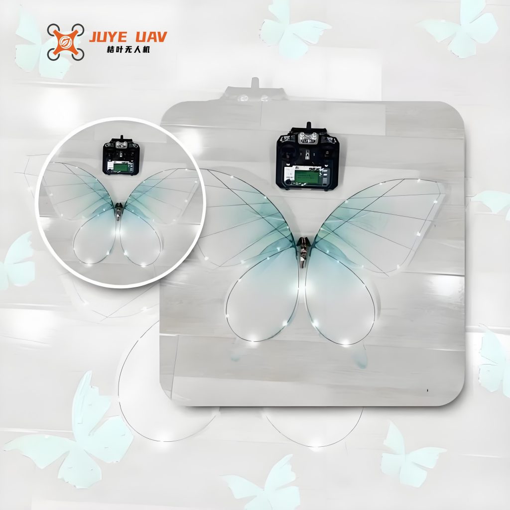
Table III summarizes the attitude control performance for three different flight modes.
| Flight Mode | Target Angle (°) | Settling Time (s) | Steady-State Error (°) |
|---|---|---|---|
| Forward flight (roll) | 0 | 0.8 | ±1.2 |
| Right turn (roll step) | 15 | 1.4 | ±0.8 |
| Hover (pitch step) | 10 | 1.1 | ±0.9 |
Wireless Communication Reliability
To verify the Bluetooth link, we placed the butterfly drone at distances from 1 m to 12 m from the ground station (a smartphone running a SPP Bluetooth terminal app). We transmitted a continuous stream of attitude data at 10 Hz and counted lost packets over 60-second intervals. The packet loss rate remained below 0.5% for distances up to 9 m, but increased to 5% at 10 m and 15% at 12 m. Therefore, we set the maximum operational range to 9 m. The measured maximum round-trip latency was 28 ms, which is acceptable for closed-loop control.
Free Flight Performance
Finally, we conducted indoor free-flight tests in a 10 m × 6 m hall. The butterfly drone was launched by hand at a slight upward angle (~15°). After a brief transient (1–2 s), the attitude controller stabilized the vehicle, and it achieved forward flight at approximately 1.5 m/s. The wing flapping frequency was set to 4 Hz. The butterfly drone successfully executed left and right turns with radii of about 2 m. The flight endurance was measured at 4 minutes and 20 seconds with a fully charged battery. Post-flight analysis of the IMU log revealed that the roll angle during turns reached ±25° with minimal overshoot. The total mass of 37.5 g was confirmed, and no structural damage occurred after multiple flights.
The measured lift-to-weight ratio can be estimated from the flight video. Using frame-by-frame analysis, the vertical acceleration during the upstroke was approximately 1.2 g, indicating a peak lift of 0.44 N, which is 1.2 times the weight. This excess lift accounts for the climbing capability observed during initial launch. The corresponding power consumption was around 3.5 W (0.4 A × 4.2 V × 2 servos at 50% duty), yielding a power-to-weight ratio of 93 W/kg, which is competitive for micro flapping-wing drones.
Conclusion
We have designed, analyzed, and tested a bio-inspired butterfly drone that successfully addresses the mass-power trade-off inherent in miniaturized flapping-wing vehicles. By using dual-servo direct drive and carbon fiber construction, the butterfly drone achieves a record low mass of 37.5 g while maintaining sufficient lift for stable forward flight and turning. The integration of an STM32 microcontroller, MPU6050 IMU, and Bluetooth module provides an effective closed-loop control system with real-time attitude stabilization and wireless command. Experimental results confirm that the butterfly drone can fly for over 4 minutes and maintain wireless communication up to 9 m. The detailed mass distribution, servo kinematics, and PID control formulas presented in tables and equations offer a reproducible framework for further optimization. Future work will focus on adding autonomous navigation sensors and improving battery efficiency to extend flight time. This butterfly drone represents a significant step toward practical micro aerial vehicles for surveillance, environmental monitoring, and search-and-rescue operations in confined spaces.