
This paper presents a comprehensive study on the control design for the transition mode of a compound-wing vertical take-off and landing (VTOL) China UAV drone. The unique transition phase from rotor hover to fixed-wing forward flight poses critical challenges due to speed-altitude coupling and varying aerodynamic efficiency. Two distinct control strategies—phased transition and full-process transition—are proposed and analyzed. Based on the longitudinal dynamic model of the compound-wing China UAV drone, a multi-controller cooperative architecture is developed, integrating fixed-wing speed and altitude-attitude controllers with rotor mode altitude and pitch controllers. A weighted control allocation algorithm using airspeed as the scheduling variable ensures smooth authority migration between the two actuator groups. Simulation results demonstrate that both strategies successfully accomplish the transition mission, maintaining altitude fluctuations within 1 m and achieving smooth velocity and attitude profiles. Furthermore, a quantitative performance evaluation using a weighted index method indicates that the phased transition strategy outperforms the full-process approach in terms of transition time and energy consumption, providing a more efficient solution for China UAV drone transition control.
1. Introduction
The China UAV drone industry has witnessed rapid growth in recent years, with compound-wing VTOL designs emerging as a key technology for applications requiring both vertical agility and long-endurance flight. Typical China UAV drone missions, such as aerial mapping, disaster monitoring, and logistics delivery, demand seamless transition between rotor-based hover and fixed-wing cruise. This transition mode, however, presents significant control challenges because the aerodynamic lift gradually shifts from rotor thrust to wing-generated lift while the airspeed increases from zero to cruise speed. The strong coupling between speed and altitude, combined with the nonlinear and time-varying dynamics, requires robust and well-coordinated control strategies.
Previous studies on China UAV drone transition control have explored both full-process and phased approaches. Some researchers have developed nonlinear control methods such as sliding mode control or adaptive control to handle the entire transition in one unified framework. Others have divided the transition into speed segments, designing separate controllers for low-speed and high-speed regions. While these methods have demonstrated feasibility, a direct quantitative comparison of their performance—considering metrics like transition time, energy consumption, and altitude stability—remains insufficiently addressed. Moreover, many existing designs rely on complex algorithms that may hinder practical implementation on resource-constrained China UAV drone platforms.
In this work, we propose two practical control strategies for the transition mode of a compound-wing China UAV drone: a phased transition strategy that activates rotor control during low-speed acceleration and gradually hands over to fixed-wing control, and a full-process transition strategy that employs both actuator sets simultaneously throughout the entire transition. Both strategies are built on classical PID and LADRC controllers, ensuring ease of tuning and implementation. A weighted control allocation law based on airspeed is introduced to dynamically distribute control efforts between rotor and fixed-wing systems. The contributions of this paper are:
- Development of a longitudinal dynamic model suitable for the transition mode of a compound-wing China UAV drone.
- Design of two distinct control strategies with explicit stage definitions and corresponding controller architectures.
- Introduction of a performance evaluation framework with three weighted metrics: altitude stability, transition time, and energy consumption.
- Comprehensive simulation-based comparison, demonstrating the superiority of the phased strategy for typical China UAV drone missions.
2. Longitudinal Dynamic Modeling
The compound-wing China UAV drone consists of a fixed-wing airframe with a quadrotor configuration mounted on the wings and fuselage, as commonly seen in VTOL China UAV drone designs. The coordinate systems used are the geographic frame (g-frame), body frame (b-frame), and wind frame (a-frame). The longitudinal dynamics are derived by combining the forces and moments from both the fixed-wing and rotor subsystems.
The aerodynamic forces from the fixed-wing section are expressed as:
$$
\begin{aligned}
L &= 0.5 \rho V_t^2 S C_L, \\
D &= 0.5 \rho V_t^2 S C_D, \\
Y &= 0.5 \rho V_t^2 S C_Y,
\end{aligned}
$$
where $\rho$ is air density, $V_t$ is true airspeed, $S$ is wing area, and $C_L$, $C_D$, $C_Y$ are the lift, drag, and side force coefficients respectively. The aerodynamic moments are:
$$
\begin{aligned}
L_{\text{fixed}} &= 0.5 \rho V_t^2 S b C_l, \\
M_{\text{fixed}} &= 0.5 \rho V_t^2 S c C_m, \\
N_{\text{fixed}} &= 0.5 \rho V_t^2 S b C_n,
\end{aligned}
$$
with $b$ as wingspan, $c$ as mean aerodynamic chord, and $C_l$, $C_m$, $C_n$ as rolling, pitching, and yawing moment coefficients.
The rotor forces and moments for a quadrotor in X-configuration are given by:
$$
\begin{aligned}
F_{\text{quad}}^b &= C_T (\omega_1^2 + \omega_2^2 + \omega_3^2 + \omega_4^2), \\
L_{\text{quad}} &= d C_T (-\omega_1^2 – \omega_2^2 + \omega_3^2 + \omega_4^2), \\
M_{\text{quad}} &= d C_T (\omega_1^2 – \omega_2^2 – \omega_3^2 + \omega_4^2), \\
N_{\text{quad}} &= C_M (-\omega_1^2 + \omega_2^2 – \omega_3^2 + \omega_4^2),
\end{aligned}
$$
where $C_T$ and $C_M$ are thrust and torque coefficients, $d$ is the moment arm, and $\omega_i$ are rotor speeds.
Superimposing both subsystems and considering only longitudinal motion, the forces in the wind frame and pitching moment in the body frame are:
$$
\begin{aligned}
F_x^a &= P \cos\alpha – D – F_{\text{quad}}^b \sin\alpha – mg \sin\gamma, \\
F_z^a &= -P \sin\alpha – L – F_{\text{quad}}^b \cos\alpha + mg \cos\gamma, \\
M_y^b &= M_{\text{fixed}}^b + M_{\text{quad}},
\end{aligned}
$$
where $P$ is the fixed-wing propeller thrust, $\alpha$ is angle of attack, $\gamma$ is flight path angle, and $g$ is gravity acceleration. The longitudinal equations of motion are then:
$$
\begin{aligned}
\dot{V}_t &= \frac{F_x^a}{m}, \\
\dot{\alpha} &= \frac{F_z^a}{m V_t} + q, \\
\dot{q} &= \frac{M_y^b}{I_y}, \\
\dot{\theta} &= q, \\
\dot{H} &= V_t \sin(\theta – \alpha),
\end{aligned}
$$
where $q$ is pitch rate, $\theta$ is pitch angle, $H$ is altitude, and $I_y$ is the pitch moment of inertia. This model (Eq. 1–5) forms the basis for control law design for the China UAV drone transition mode.
3. Control Strategy Design
3.1 Phased Transition Strategy
The phased strategy divides the transition into two distinct stages based on airspeed. In the low-speed stage (0 to stall speed, e.g., 11 m/s for our China UAV drone), the fixed-wing aerodynamic surfaces are ineffective, so the rotor system exclusively handles altitude and attitude control. The propeller throttle is opened to 90% to accelerate quickly through this region. Once the semi-stall speed is reached, the high-speed stage begins. Here the fixed-wing control surfaces become effective and gradually take over altitude and pitch control. The rotor system serves as an auxiliary to compensate for insufficient wing lift, with its weight decreasing to zero as speed approaches the cruise value. This staged approach respects the physical characteristics of the China UAV drone at different speeds and avoids unnecessary rotor usage at high speeds.
3.2 Full-Process Transition Strategy
In contrast, the full-process strategy uses both rotor and fixed-wing actuators simultaneously from start to finish. The control authority is distributed continuously via a speed-dependent weight function. The rotor provides altitude and pitch assistance throughout, while the fixed-wing controller handles speed and altitude-pitch control. This strategy is simpler in terms of logic but demands more coordinated tuning to prevent actuator conflicts. It is representative of unified control approaches commonly found in China UAV drone research.
3.3 Weighted Control Allocation
To smoothly transition between rotor and fixed-wing dominance, we introduce a weight function based on airspeed. The fixed-wing weight is defined as:
$$
\omega_{\text{fix}} = \frac{V_t^2 – V_{\min}^2}{V_{\max}^2 – V_{\min}^2},
$$
and the rotor weight is:
$$
\omega_{\text{rotor}} = 1 – \omega_{\text{fix}}.
$$
Here $V_{\min}$ and $V_{\max}$ are the minimum and maximum speeds for allocation (e.g., 0 and 25 m/s). The actual control commands to the rotor are obtained by multiplying the desired total thrust and moment by $\omega_{\text{rotor}}$, thereby reducing rotor output as airspeed increases. This allocation scheme is applied in both strategies, but the phased strategy turns off the rotor controller in high-speed stage after allocation, whereas the full-process strategy keeps it active with decreasing weight.
4. Controller Design
4.1 Phased Strategy Controllers
Low-speed stage: The rotor system uses a PID altitude controller and a PID pitch controller. The altitude control law is:
$$
T = K_{p,h} e_h + K_{i,h} \int e_h dt + K_{d,h} \dot{e}_h,
$$
where $e_h = H_{\text{ref}} – H$. The pitch controller commands rotor differential thrust to achieve the desired pitch angle. The fixed-wing throttle is set open-loop at 90% for rapid acceleration.
High-speed stage: The fixed-wing system uses a cascade altitude-pitch controller. The outer loop produces a desired pitch angle:
$$
\theta_c = K_{\theta p} e_h + K_{\theta i} \int e_h dt + K_{\theta H} \dot{H},
$$
and the inner loop generates elevator deflection:
$$
\delta_e = K_{ep} e_\theta + K_{eq} q + K_{\text{alpha}} \alpha.
$$
Speed is regulated by a PID throttle controller. The rotor system during this stage employs a linear active disturbance rejection controller (LADRC) for altitude, with state-space model:
$$
\begin{aligned}
\dot{x}_1 &= x_2, \\
\dot{x}_2 &= x_3 + b_0 T, \\
\dot{x}_3 &= p_h,
\end{aligned}
$$
where $x_1=H$, $x_2=\dot{H}$, $x_3$ is the total disturbance, $b_0$ is the control gain, and $p_h$ is the disturbance derivative. A linear extended state observer (LESO) estimates the states and disturbance:
$$
\begin{aligned}
\dot{z}_1 &= z_2 + l_1(H – z_1), \\
\dot{z}_2 &= z_3 + l_2(H – z_1) + b_0 T, \\
\dot{z}_3 &= l_3(H – z_1).
\end{aligned}
$$
The control law with disturbance compensation is:
$$
\begin{aligned}
u_0 &= K_p (H_{\text{ref}} – z_1) – K_d z_2, \\
T &= \frac{u_0 – z_3}{b_0}.
\end{aligned}
$$
The rotor altitude command is then multiplied by the decreasing weight $\omega_{\text{rotor}}$ so that its contribution fades to zero at cruise.
4.2 Full-Process Strategy Controllers
In the full-process strategy, the fixed-wing controllers remain the same as in the high-speed stage of the phased strategy, but they are active from the beginning. The rotor system uses a PID altitude controller (same as Eq. 10) and a PID pitch controller throughout the transition. The weighted allocation (Eq. 6–7) is applied to the total desired thrust and pitch moment, with the rotor weight decreasing from 1 to 0 as speed increases. No stage-based switching is employed.
5. Simulation and Analysis
5.1 Simulation Setup
The China UAV drone model used in simulations has a mass of 15 kg, wing area of 0.8 m², and a cruise speed of 25 m/s. Initial condition is hover at 100 m altitude. The transition starts with zero airspeed and ends when the drone reaches 25 m/s with trim angle of attack (2.34°). The maximum rotor speed is 2224 rpm. The performance metrics are defined as:
- Altitude stability: maximum deviation from reference altitude.
- Transition time: time from start to reaching cruise speed with stabilized pitch.
- Energy consumption: normalized average actuator effort, combining fixed-wing throttle and rotor speeds.
A weighted index is computed as:
$$
J = 0.5 \cdot \frac{\Delta H_{\max}}{H_{\text{ref}}} + 0.25 \cdot \frac{t}{t_0} + 0.25 \cdot \bar{\delta}_t,
$$
where $\Delta H_{\max}$ is maximum altitude error, $t_0$ is the longer transition time between the two strategies, and $\bar{\delta}_t$ is the normalized average actuator output defined as:
$$
\bar{\delta}_t = \frac{1}{t_f} \int_0^{t_f} \delta(\tau) d\tau,
$$
with $\delta(\tau)$ being the combined throttle and rotor speed effort.
5.2 Results: Phased Transition Strategy
The phased strategy simulation results show rapid acceleration in the low-speed stage with 90% throttle, reaching semi-stall speed in about 3 seconds. Altitude deviation remains below 0.5 m. During the high-speed stage, the fixed-wing controller smoothly takes over, with pitch angle converging to the trim value without overshoot. Rotor speed decreases gradually to zero as weight reduces. The entire transition completes in 8.5 seconds.
5.3 Results: Full-Process Transition Strategy
Under the full-process strategy, both actuator sets work simultaneously. The speed profile accelerates more gradually, taking about 12 seconds to reach cruise speed. Altitude deviation is slightly larger but still within 1 m. Pitch angle exhibits a small overshoot of 0.7°. Rotor speeds reduce smoothly, but they remain active longer, resulting in higher total energy consumption.
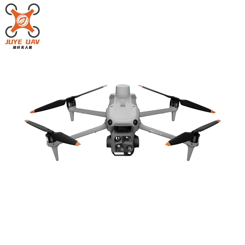
Figure 1 illustrates a representative China UAV drone used in this study. The simulation results are summarized and compared below.
5.4 Comparative Analysis
Table 1 presents the quantitative comparison of the two strategies. The phased strategy achieves a lower weighted index J = 0.28, compared to J = 0.35 for the full-process strategy, indicating superior overall performance.
| Metric | Phased Transition | Full-Process Transition |
|---|---|---|
| Max altitude deviation (m) | 0.010 | 0.0065 |
| Transition time (s) | 8.5 | 12.0 |
| Normalized transition time (t/t0) | 0.67 | 1.00 |
| Average actuator effort | 0.43 | 0.49 |
| Weighted index J | 0.28 | 0.35 |
The phased strategy shows a 29% reduction in transition time and 12% reduction in average actuator effort compared to the full-process strategy. Although the full-process strategy exhibits slightly better altitude stability (0.0065 m vs 0.010 m), the difference is negligible in practice. The phased strategy’s ability to quickly pass through the low-efficiency low-speed regime and reduce rotor usage at higher speeds contributes to its overall advantage.
It is worth noting that the controller parameters used in both strategies are tuned through a systematic process to ensure fair comparison. The same PID gains for fixed-wing controllers and LADRC bandwidths for rotor controllers are retained. The only difference is the stage-switching logic and the activation of rotor control in the low-speed stage of the phased strategy. This highlights the effectiveness of the control architecture for China UAV drone applications.
6. Conclusion
This paper has presented a detailed design and comparison of two transition control strategies for a compound-wing China UAV drone. The phased transition strategy leverages the distinct aerodynamic characteristics at low and high speeds by activating rotor control only when needed, leading to faster transition and lower energy consumption. The full-process strategy, while simpler in logic, requires more time and energy to achieve the same mission. Quantitative analysis using weighted metrics confirms that the phased approach is the more efficient choice for China UAV drone transition control.
Future work will extend this study to include wind disturbance rejection, three-dimensional maneuvers, and integration with mission planning systems. The proposed control framework is well-suited for real-time implementation on embedded China UAV drone flight controllers, offering a practical solution for operational deployment.