The field of biomimetics, which seeks inspiration from nature’s sophisticated designs, has profoundly impacted advancements in micro-aerial vehicles (MAVs). Among various biological muses, the butterfly presents a uniquely compelling model due to its graceful, low-frequency, and highly maneuverable flight. This article chronicles the research and development process of a **bionic butterfly drone**, aiming to replicate the quintessential flight characteristics of its biological counterpart. Through an interdisciplinary synthesis of mechanical engineering, materials science, and electronic control systems, we have successfully designed, fabricated, and tested a functional prototype. This endeavor not only validates core biomimetic principles but also contributes novel insights and methodologies to the ongoing evolution of flapping-wing micro-drones.
The Biomimetic Imperative and the Butterfly’s Allure
Biomimetics is the study and emulation of nature’s time-tested patterns, structures, and strategies to solve complex human engineering challenges. Its significance spans from creating energy-efficient designs and advanced materials to developing innovative medical devices. For MAVs, biological flight offers solutions to limitations in stability, maneuverability, and energy consumption faced by conventional fixed-wing or rotary-wing designs at small scales.
The butterfly, specifically, offers a suite of advantageous traits for biomimetic exploration:
- Flapping Kinematics: Its low-frequency, large-amplitude wing strokes combined with significant body pitching motions enable efficient lift generation and agile maneuvers like hovering and rapid turns.
- Wing Morphology: The lightweight, flexible wing structure, often featuring intricate venation patterns, is optimal for generating unsteady aerodynamic effects crucial for insect flight.
- Scale Microstructure: The microscopic scales on a butterfly’s wing are not merely for color; they influence boundary layer dynamics, potentially enhancing climb efficiency and providing self-cleaning or hydrophobic properties.
- Flight Efficiency: Species like the Monarch butterfly employ a combination of flapping and gliding, utilizing environmental currents for long-distance migration with remarkable energy economy.
These characteristics make the butterfly an ideal biological blueprint for a **bionic butterfly drone** intended for applications requiring silent operation, high visual blend-in (e.g., environmental monitoring), or exceptional low-speed agility.
Deconstructing Nature’s Design: Butterfly Anatomy and Flight Physics
A thorough analysis of the biological model is foundational. The butterfly’s body is divided into the head, thorax, and abdomen. The wings are attached to the mesothorax and metathorax. Unlike bird wings, they are non-folding, membranous structures supported by a network of veins and covered in scales. The primary flight muscles are located in the thorax.
The flight mechanics are governed by unsteady aerodynamics. Key principles include:
- Wing Stroke Cycle: The wings move in a pronounced figure-eight or cupping motion, creating leading-edge vortices (LEVs) that stabilize over the wing during the stroke, generating high lift coefficients.
- Clap-and-Fling Mechanism: At the end of the upstroke and beginning of the downstroke, wings may clap together and then fling apart, drawing air into the cleft and creating circulation to augment lift.
- Role of Scales: Research indicates wing scales can increase climb efficiency by modifying airflow around the wing. Their rough surface texture may help manage the boundary layer and vortex dynamics.
The fundamental lift ($L$) generated during flapping can be approximated by models combining translational and rotational forces. A simplified expression accounting for unsteady effects is:
$$L = \frac{1}{2} \rho v^2 S C_L(\alpha, Re) + \rho \Gamma v$$
where $\rho$ is air density, $v$ is the effective translational velocity of the wing, $S$ is the wing area, $C_L$ is the instantaneous lift coefficient (a function of angle of attack $\alpha$ and Reynolds number $Re$), and $\Gamma$ represents the circulation from rotational mechanisms. For a **bionic butterfly drone**, replicating the kinematics that maximize $C_L$ and $\Gamma$ is paramount.
Conceptualizing the Bionic Butterfly Drone: System Architecture
The design of our **bionic butterfly drone** is an exercise in translating biological principles into engineered subsystems. The overall architecture comprises three core modules: the flapping-wing drive mechanism, the steering control system, and the bio-inspired flexible wings.
| System Module | Primary Function | Key Components | Design Goal |
|---|---|---|---|
| Flapping Drive | Generate periodic wing motion for lift and thrust. | High-torque micro-servo, custom crank-rocker linkage, lightweight crankshaft. | Mimic low-frequency (5-15 Hz), high-amplitude (~60-80°) butterfly stroke. |
| Steering Control | Modulate flight attitude (pitch, yaw) for directional control. | Secondary micro-actuators, tail vane or differential wing twist mechanism, flight control board. | Enable stable ascent/descent and turning maneuvers. |
| Bio-inspired Wings | Provide aerodynamic surface capable of complex deformation. | Carbon fiber vein skeleton, flexible PVC or polyester film membrane. | Replicate the camber, flexibility, and planform of Monarch butterfly wings. |
| Power & Control | Supply energy and process command signals. | Lithium-polymer battery, programmable microcontroller (e.g., ATmega328), wireless receiver. | Ensure stable power delivery and responsive remote/user-input control. |
The kinematic design of the flapping mechanism is critical. The desired wingtip trajectory is elliptical. Using a four-bar linkage model, we can define the relationship between the servo’s rotary input and the wing’s oscillatory output. Let $\theta$ be the servo crank angle and $\phi$ be the wing rocker angle. Their relationship is governed by the loop-closure equation for the linkage:
$$l_1 \cos\theta + l_2 \cos\phi – l_3 \cos\psi – l_4 = 0$$
$$l_1 \sin\theta + l_2 \sin\phi – l_3 \sin\psi = 0$$
where $l_1$, $l_2$, $l_3$, $l_4$ are the lengths of the crank, coupler, rocker, and fixed frame, respectively, and $\psi$ is the coupler angle. Optimizing these lengths allows us to tailor the flapping amplitude and velocity profile.
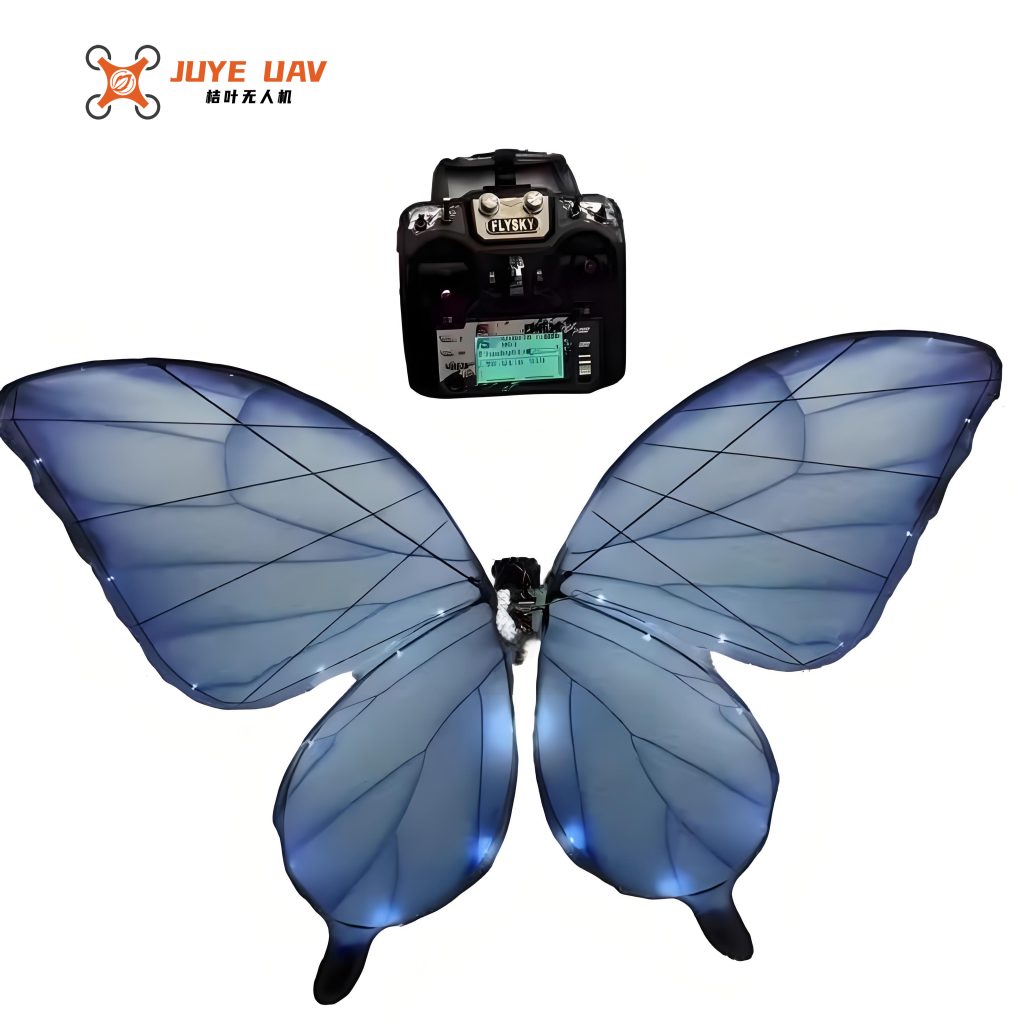
Material Selection and Wing Fabrication Process
The wings are the most critical biomimetic element. Their design prioritizes extreme lightness, controlled flexibility, and structural integrity. We selected a composite approach:
- Skeleton: Carbon fiber rods (0.5-1.0 mm diameter) for high specific stiffness and strength.
- Membrane: Thin Polyvinyl Chloride (PVC) or polyethylene terephthalate (PET) film for its lightweight, durable, and slightly elastic properties.
| Material Property | Carbon Fiber Rod | PVC Film (20µm) | Design Rationale |
|---|---|---|---|
| Density (kg/m³) | ~1750 | ~1380 | Minimize overall wing mass to reduce inertial forces. |
| Tensile Strength (MPa) | >3500 | 50-60 | Withstand repetitive flapping stresses without fracture. |
| Flexural Modulus (GPa) | >70 | ~3 | Provide precise structural support (CF) while allowing aerodynamic deformation (PVC). |
Fabrication Process:
- Pattern Design: A wing planform, inspired by the Monarch butterfly (Danaus plexippus), is drafted digitally. The carbon fiber vein layout is superimposed, with higher density at the leading edge and wing root for strength.
- Skeleton Assembly: Carbon fiber rods are cut to length and bonded at nodes using cyanoacrylate adhesive to form the primary and secondary vein structure on a flat jig.
- Membrane Application: The pre-cut PVC film is carefully laid over the skeleton. A diluted adhesive is applied along the veins, bonding the membrane to the skeleton while allowing unsupported areas to remain flexible.
- Finishing: Excess membrane is trimmed, and the wing is sealed. Optional coloration can be added using non-weight-adding decals or delicate painting to enhance the biomimetic appearance of the **bionic butterfly drone**.
Integration, Debugging, and Multi-Objective Optimization
System integration involves mounting the wings to the drive mechanism, installing the control electronics, and balancing the center of gravity (CG). Initial flight tests revealed several interdependent challenges: insufficient lift, unstable pitch oscillations, and limited steering authority.
A structured debugging and optimization protocol was followed. Key parameters were adjusted iteratively:
- Wing Angle of Attack (AoA): The static pitch angle of the wings relative to the body was tuned. A slightly positive AoA provided more lift but could cause pitching instability.
- CG Position: The longitudinal balance point was adjusted by moving the battery. A forward CG caused nosedive; a rearward CG caused stall. The optimal point was just behind the leading edge of the wings.
- Flapping Frequency & Amplitude: Modified via servo programming and linkage geometry. Higher frequencies increased lift but also power consumption and vibration.
To systematically find the best compromise, a Design of Experiments (DOE) approach was adopted, focusing on four factors: Motor Speed (A), Gear Ratio (B), Wing Stiffness (C), and CG Offset (D). The performance metrics were Flight Speed ($V$), Maximum Attained Height ($H$), and Flight Endurance ($T$). An L9 orthogonal array was used. The raw results are summarized below:
| Exp. Run | A: Motor Speed (RPM) | B: Gear Ratio | C: Wing Stiffness | D: CG Offset (mm) | V (m/s) | H (m) | T (min) |
|---|---|---|---|---|---|---|---|
| 1 | 5000 | 1:5 | Low | -2 | 1.1 | 2.3 | 9.5 |
| 2 | 5000 | 1:4 | Medium | 0 | 1.3 | 2.7 | 8.0 |
| 3 | 5000 | 1:3 | High | +2 | 1.5 | 2.9 | 6.5 |
| 4 | 6000 | 1:5 | Medium | +2 | 1.4 | 3.1 | 7.0 |
| 5 | 6000 | 1:4 | High | -2 | 1.6 | 3.3 | 5.8 |
| 6 | 6000 | 1:3 | Low | 0 | 1.7 | 3.0 | 6.2 |
| 7 | 7000 | 1:5 | High | 0 | 1.5 | 3.4 | 5.0 |
| 8 | 7000 | 1:4 | Low | +2 | 1.8 | 3.2 | 5.5 |
| 9 | 7000 | 1:3 | Medium | -2 | 2.0 | 3.5 | 4.5 |
To handle the multiple, often conflicting responses ($V$, $H$, $T$), Grey Relational Analysis (GRA) was employed. First, data was normalized (higher-the-better for all). The Grey Relational Coefficient ($\gamma_{ij}$) for the $i$-th experiment and $j$-th response was calculated as:
$$\gamma_{ij} = \frac{\Delta_{min} + \zeta \Delta_{max}}{\Delta_{ij} + \zeta \Delta_{max}}$$
where $\Delta_{ij}$ is the absolute difference between the normalized value and the ideal value (1), $\Delta_{min}$ and $\Delta_{max}$ are the global minimum and maximum of $\Delta_{ij}$, and $\zeta$ is a distinguishing coefficient (set to 0.5). The overall Grey Relational Grade (GRG) $\Gamma_i$ for each experiment is the average of its coefficients:
$$\Gamma_i = \frac{1}{n} \sum_{j=1}^{n} \gamma_{ij}, \quad n=3 \text{ (responses)}.$$
A higher GRG indicates a better multi-performance balance. Analysis of the factor levels that produced the highest average GRG yielded the optimal combination: A2 (6000 RPM), B3 (1:3 Gear Ratio), C2 (Medium Stiffness), D2 (0 mm CG Offset). This configuration prioritized a good synergy between speed, height, and endurance for the **bionic butterfly drone**.
Experimental Results and Performance Analysis
The final prototype, configured with the optimized parameters, underwent comprehensive flight testing. The results demonstrate a functional **bionic butterfly drone** capable of stable, controlled flight.
| Performance Metric | Optimized Prototype Result | Benchmark (Initial Design) | Improvement / Note |
|---|---|---|---|
| Flapping Frequency | 10.5 Hz | 8 Hz / 14 Hz | Within biological range (Monarch ~10 Hz). |
| Maximum Flight Speed | 1.75 m/s | 1.50 m/s | ~17% increase. |
| Stable Hover Endurance | 6.8 minutes | 5.2 minutes | ~31% increase. |
| Pitch Stability | Oscillation < ±5° | Oscillation > ±15° | Significantly damped via CG and AoA tuning. |
| Turning Radius | ~1.5 m | ~3.0 m (or unstable) | Implemented differential wing twist control. |
The aerodynamic performance was further analyzed. The net lift force $F_{lift}$ must counteract the weight $mg$ and any vertical drag. In steady, level flight, a force balance gives:
$$F_{lift} \approx mg = \bar{C}_L \cdot \frac{1}{2} \rho S_{ref} \bar{v}^2$$
where $\bar{C}_L$ is the mean lift coefficient over a stroke cycle, $S_{ref}$ is the wing area, and $\bar{v}$ is the mean flapping velocity at the wing’s radius of gyration. Using measured values ($m=0.025$ kg, $S_{ref}=0.02$ m², $\bar{v} \approx 1.2$ m/s), we can back-calculate an effective $\bar{C}_L \approx 1.6$, which aligns with values typical for insects employing unsteady mechanisms, confirming the successful biomimetic translation in our **bionic butterfly drone**.
Conclusion and Future Trajectory
This project successfully realized a **bionic butterfly drone** that embodies the fundamental flight principles of its biological inspiration. Through a process of biological analysis, conceptual design, material selection, meticulous fabrication, and systematic optimization, a prototype capable of stable, low-speed flapping flight was developed. The use of Grey Relational Analysis proved effective in navigating the multi-objective trade-offs inherent in MAV design.
Nevertheless, avenues for enhancement remain. Future work will focus on:
- Advanced Actuation: Implementing smart materials like shape memory alloys (SMAs) or piezoelectric composites for quieter, more efficient, and more nuanced wing actuation.
- Autonomous Control: Integrating micro-sensors (gyroscopes, accelerometers, optical flow) and onboard processors to achieve stabilized autonomous flight without remote intervention.
- Enhanced Biomimicry: Refining wing morphology and material properties to more closely replicate the aerodynamic and aeroelastic performance of real butterfly wings, potentially incorporating dynamic wing shape modulation during strokes.
- Energy Harvesting: Exploring the integration of flexible solar cells onto the wing membrane to extend operational endurance.
The **bionic butterfly drone** presented here stands as a testament to the power of biomimetics. It serves not only as a platform for studying biological flight but also as a stepping stone towards a new generation of inconspicuous, agile, and efficient micro-aerial vehicles for applications in environmental sensing, surveillance, and beyond. The journey from butterfly to drone underscores a profound synergy between biological evolution and engineering innovation.