The field of biomimetic flapping-wing micro air vehicles (MAVs) has seen significant advancements, driven by their potential for high aerodynamic efficiency, exceptional maneuverability, and low observability. Among various biological inspirations, the butterfly presents a fascinating model due to its complex wing kinematics and ability to generate substantial lift from seemingly low-frequency flapping motions. This paper presents the design and analysis of a novel, lightweight flying butterfly drone. The primary challenge addressed is the common issue in miniaturization efforts: excessive mass leading to insufficient flight power. Our solution centers on a minimalist dual-servo actuation architecture and the strategic use of advanced lightweight materials. The design integrates a custom carbon fiber airframe, independently controlled wings using high-performance micro servos, and an embedded flight control system featuring real-time attitude stabilization and wireless command capability. This flying butterfly drone represents a significant step towards practical, agile, and efficient bio-inspired MAVs.
1. Overall Mechanical Architecture and Design Philosophy
The core design philosophy for this flying butterfly drone is structural simplicity and mass minimization to overcome power-to-weight ratio limitations. The airframe abandons complex linkage mechanisms typically found in ornithopters in favor of direct servo-driven wing flapping. This approach reduces parts count, friction, and overall mass while increasing control fidelity.
The central fuselage, or servo mount, is fabricated via 3D printing using continuous carbon fiber-reinforced polymer. This material offers an exceptional strength-to-weight ratio, crucial for the flying butterfly drone’s performance. A 3mm diameter carbon fiber rod (Rod 1, length: 10mm) is inserted through an axial hole in this mount, forming the primary forward spine. Research indicates that body oscillation during flight can enhance vortex generation and lift. To incorporate this bio-inspired feature, a segment of silicone tubing (OD: 4mm, ID: 2mm, length: 20mm) is attached to Rod 1. This flexible joint allows passive pitching motion of the aft body section. A second carbon rod (Rod 2, length: 80mm) is inserted into the tubing, serving as the platform for the flight controller and battery, whose position can be adjusted to tune the center of gravity.
Each wing pair (left and right) consists of a forewing and a hindwing, rigidly connected using specialized joints (Connectors 1 & 4). This configuration ensures the entire wing area acts as a unified lifting surface during both upstroke and downstroke, maximizing the effective area for force generation per flapping cycle. The wing skeleton (venation) is constructed from a network of 1mm diameter carbon fiber rods. Connectors 2, 3, and 4 facilitate the assembly of this complex lattice, ensuring structural integrity and precise geometry. The wing membrane is crafted from P31n ripstop nylon, a material chosen for its high tensile strength, minimal weight, and vibrant color options, enabling both functional durability and realistic visual mimicry of a flying butterfly drone. The key structural components and their functions are summarized in Table 1.
| Component | Material / Specification | Primary Function |
|---|---|---|
| Servo Mount (Fuselage) | 3D-Printed Carbon Fiber Polymer | Houses and aligns servo motors, primary load-bearing structure. |
| Body Rod 1 | Carbon Fiber, Ø3mm x 10mm | Provides rigid forward spine and servo attachment point. |
| Flexible Body Joint | Silicone Tubing, Ø4/2mm x 20mm | Enables passive body pitching to potentially enhance lift. |
| Body Rod 2 (Tail Boom) | Carbon Fiber, Length: 80mm | Supports flight electronics and battery; adjustable for CG tuning. |
| Wing Skeleton (Venation) | Carbon Fiber Rods, Ø1mm | Forms lightweight, rigid framework defining wing shape and providing attachment for membrane. |
| Wing Membrane | P31n Ripstop Nylon | Provides aerodynamic surface; lightweight, durable, and colorful. |
| Wing-to-Servo Connector (Connector 1) | 3D-Printed Polymer | Directly mates wing root to servo arm, allowing for angle of attack adjustment. |
The wing root connection is designed for both robustness and adjustability. Connector 1 plugs directly into a matching socket on the servo arm. This direct-drive interface simplifies assembly, allows for fine-tuning of the wing’s initial incidence angle (an important parameter for lift and thrust generation), and facilitates rapid wing replacement—a valuable feature for experimental testing of different wing geometries on the flying butterfly drone.
2. Control System Design and Implementation
The flight control system is the “brain” of the flying butterfly drone, responsible for executing flight maneuvers, maintaining stability, and enabling user interaction. It is built around a hierarchical architecture comprising sensing, computation, actuation, and communication modules.
2.1 Hardware Design and Component Selection
2.1.1 Servo Actuation Module: Wing actuation is performed by two KST X80plus micro digital metal-gear servos. Selected for their compact size (23.5×8.0x16.7 mm), low mass (9g each), and high torque output relative to their size, these servos are ideal for the flying butterfly drone. They are controlled via Pulse-Width Modulated (PWM) signals. A standard PWM signal for servos has a period of 20ms (50Hz frequency). The pulse width within this period dictates the angular position of the servo output shaft, typically following a linear relationship over a 0° to 180° range. For the KST X80plus, the mapping is approximately:
$$\theta_{\text{servo}} = k \cdot (PW – PW_{\text{min}})$$
where $\theta_{\text{servo}}$ is the servo angle, $PW$ is the pulse width in milliseconds, $PW_{\text{min}}$ is the pulse width corresponding to 0° (e.g., 0.5ms), and $k$ is a scaling constant (e.g., 180°/2.0ms = 90°/ms). The performance characteristics under different operating voltages are critical for power management and are detailed in Table 2.
| Supply Voltage (V) | Stall Torque (N·m) | Speed (sec/60°) |
|---|---|---|
| 3.8 | 0.240 | 0.18 |
| 6.0 | 0.385 | 0.15 |
| 7.4 | 0.485 | 0.12 |
| 8.4 | 0.530 | 0.09 |
The flapping frequency $f_{\text{flap}}$ of the flying butterfly drone is directly controlled by the frequency of a periodic positional command sent to the servos, typically between 1-5 Hz. As aerodynamic forces are functions of flapping frequency, amplitude, and phase, these become the primary control inputs:
– Forward Flight: Achieved by commanding both servos with identical trajectories (same frequency $f$, amplitude $A$, and phase $\phi$). This produces symmetric forces, resulting in a net forward thrust $F_T$ and lift $F_L$.
– Yaw Turn (Turning): Executed by introducing a phase difference $\Delta \phi$ between the left and right wing motions, or by modulating their amplitudes differentially. This creates an asymmetry in horizontal force components, generating a yawing moment $M_z$. If the left wing leads in phase or has a larger amplitude, it generally produces more drag/thrust, turning the flying butterfly drone to the right, and vice versa.
2.1.2 Attitude Sensing Module (MPU6050): Flight stability is paramount. An MPU6050 inertial measurement unit (IMU) provides real-time attitude data. This chip integrates a 3-axis gyroscope and a 3-axis accelerometer. The raw sensor data is processed by the chip’s built-in Digital Motion Processor (DMP) to yield filtered and fused orientation estimates in the form of Euler angles: pitch ($\theta$), roll ($\phi$), and yaw ($\psi$). The microcontroller communicates with the MPU6050 via the I²C serial protocol to read these angles continuously, forming the feedback for the stability control loop.
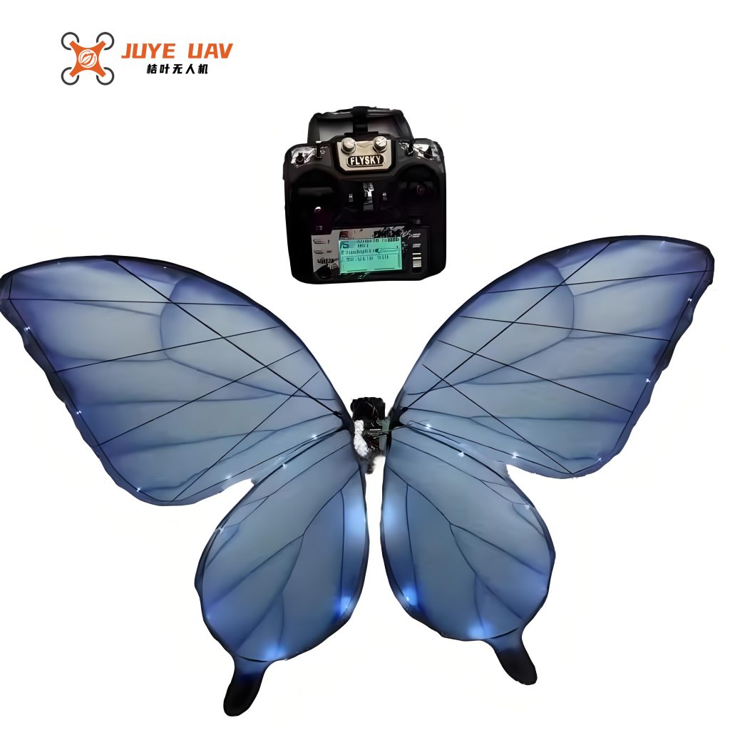
2.1.3 Wireless Communication Module (HC-05 Bluetooth): For real-time piloting and data monitoring, an HC-05 Bluetooth module is integrated. It creates a wireless serial link (UART over Bluetooth) between the flying butterfly drone and a ground station, such as a smartphone running a serial terminal application (e.g., SPP Bluetooth App). This allows the transmission of high-level commands (e.g., “turn left,” “climb”) to the drone and the telemetry of sensor data (e.g., attitude angles, battery voltage) back to the user. The module supports communication ranges up to approximately 10 meters, which is sufficient for testing and controlling the flying butterfly drone within visual line of sight.
2.2 Software Architecture and Control Algorithms
The firmware for the flight controller is developed in C using the Keil μVision IDE, targeting the ARM Cortex-M3 core of the STM32F103C8T6 microcontroller.
2.2.1 Main Program Flow: The software operates in a super-loop architecture with interrupt service routines for time-critical tasks. After initialization of hardware (GPIO, timers, UART, I²C), the main loop continuously:
- Checks for and processes incoming commands from the Bluetooth module.
- Reads the current attitude ($\theta, \phi, \psi$) from the MPU6050 via I²C.
- Executes the high-level flight mode logic (e.g., forward flight, turn).
- Runs the PID stability controller to compute corrective servo commands based on attitude error.
- Updates the PWM outputs for the two servos via dedicated hardware timers (Timer 3 and Timer 4).
2.2.2 Servo Control & Flight Mode Implementation: Each flight mode translates to a specific pattern of PWM signals. For instance, the forward flight mode commands both servos to oscillate between 10° and 60° at a fixed frequency (e.g., 3 Hz). The required PWM duty cycle $DC$ for a desired angle $\theta_s$ is calculated as:
$$ DC(\theta_s) = DC_{0^\circ} + \frac{\theta_s}{180^\circ} \cdot (DC_{180^\circ} – DC_{0^\circ}) $$
where $DC_{0^\circ}$ and $DC_{180^\circ}$ are the duty cycles corresponding to the servo’s extreme positions. The timers generate these signals independently, allowing complete freedom for differential wing control.
2.2.3 Attitude Stabilization using PID Control: To maintain a desired flight attitude (e.g., level pitch), a Proportional-Integral-Derivative (PID) controller is implemented. The controller calculates a corrective output $u(t)$ based on the error $e(t)$ between the desired setpoint $r(t)$ and the measured process variable $y(t)$ (e.g., current pitch angle):
$$ e(t) = r(t) – y(t) $$
$$ u(t) = K_p e(t) + K_i \int_{0}^{t} e(\tau) d\tau + K_d \frac{de(t)}{dt} $$
where $K_p$, $K_i$, and $K_d$ are the proportional, integral, and derivative gains, respectively. For the flying butterfly drone, the output $u(t)$ is mapped to a bias or adjustment applied to the servo commands. For example, if the drone pitches down ($\theta$ too negative), the PID controller increases the base lift command to both wings proportionally to correct the error. The tuning of these gains is critical for stable and responsive flight of the flying butterfly drone.
3. Prototype Fabrication and Assembly
The designed flying butterfly drone was successfully manufactured and assembled. The prototype achieves remarkable lightweight construction. Key physical specifications are:
- Wingspan: 29.5 cm
- Body Length: 12.6 cm
- Total Mass: 37.5 grams
The mass breakdown in Table 3 highlights the effectiveness of the lightweight design strategy. The majority of the mass is concentrated in the essential power and actuation systems, with the airframe and wings contributing minimally.
| Component Group | Mass (grams) | Percentage of Total Mass |
|---|---|---|
| Complete Prototype | 37.5 | 100% |
| Pair of Wings (Structure & Membrane) | 5.5 | 14.7% |
| Fuselage & Actuation (Servos, Mount, Rods) | 19.0 | 50.7% |
| Electronics & Power (Battery, Flight Ctrl) | 13.0 | 34.6% |
4. System Integration, Testing, and Performance Validation
4.1 Flight Attitude Stabilization Test: The efficacy of the MPU6050-based PID controller was validated. The flying butterfly drone was commanded to execute a coordinated turn with specific target attitudes: Pitch = 17°, Roll = -45°, Yaw = -65°. The actual attitude data streamed from the IMU was captured and plotted using data visualization software (VOFA+). The results, as shown in representative data, confirmed that the controller could maintain the commanded attitudes with an error of less than ±1° for each axis during steady-state maneuvering. This demonstrates a high level of control authority and stability for the flying butterfly drone.
4.2 Wireless Communication Range and Reliability Test: The Bluetooth link was tested for robustness. With the flying butterfly drone in operation and the ground station (smartphone) at a distance of 8-9 meters, the wireless connection remained stable. Command packets were sent successfully to initiate flight mode changes, and telemetry data (attitude, system status) was received continuously without packet loss. This confirms that the HC-05 module provides a sufficiently reliable communication channel for controlling and monitoring the flying butterfly drone within a typical indoor or calm outdoor test environment.
4.3 Functional Flight Testing: Basic flight maneuvers were demonstrated. The prototype was able to:
- Take-off and Hover (近似): Generate enough lift to become airborne and maintain a roughly stationary position with manual throttle/attitude adjustments.
- Forward Flight: Translate forward at a steady pace when both wings flapped symmetrically.
- Yaw Turns: Execute left and right turns by introducing the programmed differential action between the two servos.
The successful execution of these maneuvers validates the core design principles: the dual-servo direct-drive mechanism provides adequate and controllable force, and the low overall mass of 37.5g is compatible with the power output of the selected components, effectively mitigating the “excessive mass, insufficient power” challenge.
5. Conclusion and Future Work
This paper presented the comprehensive design, implementation, and testing of a bio-inspired flying butterfly drone. The key innovation lies in its holistic lightweight approach, combining a direct-drive servo mechanism with a carbon fiber composite airframe to achieve a total mass of only 37.5g. This directly addresses a fundamental barrier in flapping-wing MAV miniaturization. The integrated control system, featuring an STM32 microcontroller, MPU6050 IMU for PID-based attitude stabilization, and HC-05 Bluetooth for wireless communication, enables stable and controllable flight, mimicking basic butterfly maneuvers such as forward flight and turning.
The flying butterfly drone serves as a successful proof-of-concept platform. Future work will focus on enhancing autonomy and performance. This includes implementing more sophisticated adaptive control algorithms to handle gusts and disturbances, integrating a magnetometer for improved yaw estimation, reducing the size and mass of the electronics further, and conducting detailed aerodynamic studies using particle image velocimetry (PIV) to optimize wing shape and kinematics for even greater efficiency. The design framework established here provides a viable and effective pathway for the continued development of agile, efficient, and truly micro-scale flying butterfly drones.