The pursuit of agile, efficient, and low-observable micro aerial vehicles has driven extensive research into biomimetic systems, particularly those mimicking the flight of birds and insects. Among these, the flying butterfly drone represents a pinnacle of lightweight and maneuverable design, drawing inspiration from the unique flight mechanics of Lepidoptera. This article details the comprehensive design, development, and analysis of a novel bio-inspired butterfly flapping-wing drone, addressing key challenges in miniaturization, structural integrity, and precise motion control through innovative engineering solutions.
Design Philosophy and Biological Inspiration
The design process for the biomimetic butterfly drone is fundamentally rooted in a bio-inspired iterative methodology. It begins with a meticulous analysis of the biological template—the butterfly—focusing on its wing morphology, kinematic patterns during flapping, and the resulting unsteady aerodynamic phenomena. Key characteristics such as the clap-and-fling mechanism, wing flexibility, and the coordination of two pairs of wings inform the initial mechanical and aerodynamic conceptual models. This biological study is then synthesized with a review of existing technological paradigms in micro-actuation, smart materials, and flight control algorithms.
Subsequent stages involve multi-domain simulation and optimization. Preliminary structural layouts are evaluated using computational fluid dynamics (CFD) for aerodynamic performance and finite element analysis (FEA) for structural strength under dynamic loads. The design undergoes multiple iterations, balancing mass, power efficiency, and reliability. High-fidelity 3D models are constructed to finalize component geometry and assembly relationships. Prototyping employs additive manufacturing and precision laser cutting, followed by the integration of sensors, controllers, and power modules. Finally, extensive flight testing in controlled environments provides empirical data on lift generation, stability, and endurance, feeding back into a refinement loop to optimize the design until target performance metrics are achieved. This closed-loop, data-driven process is encapsulated in the following design workflow.
Airframe and Wing Structural Design
The airframe of the flying butterfly drone is architected for minimal mass without compromising necessary rigidity. The primary load-bearing structure is a central boom constructed from a 3mm diameter carbon fiber rod, offering an exceptional strength-to-weight ratio. Attached to this boom is a custom-designed servo housing, fabricated using lightweight Polylactic Acid (PLA) via 3D printing. This housing securely mounts the twin drive actuators which form the core of the propulsion system.
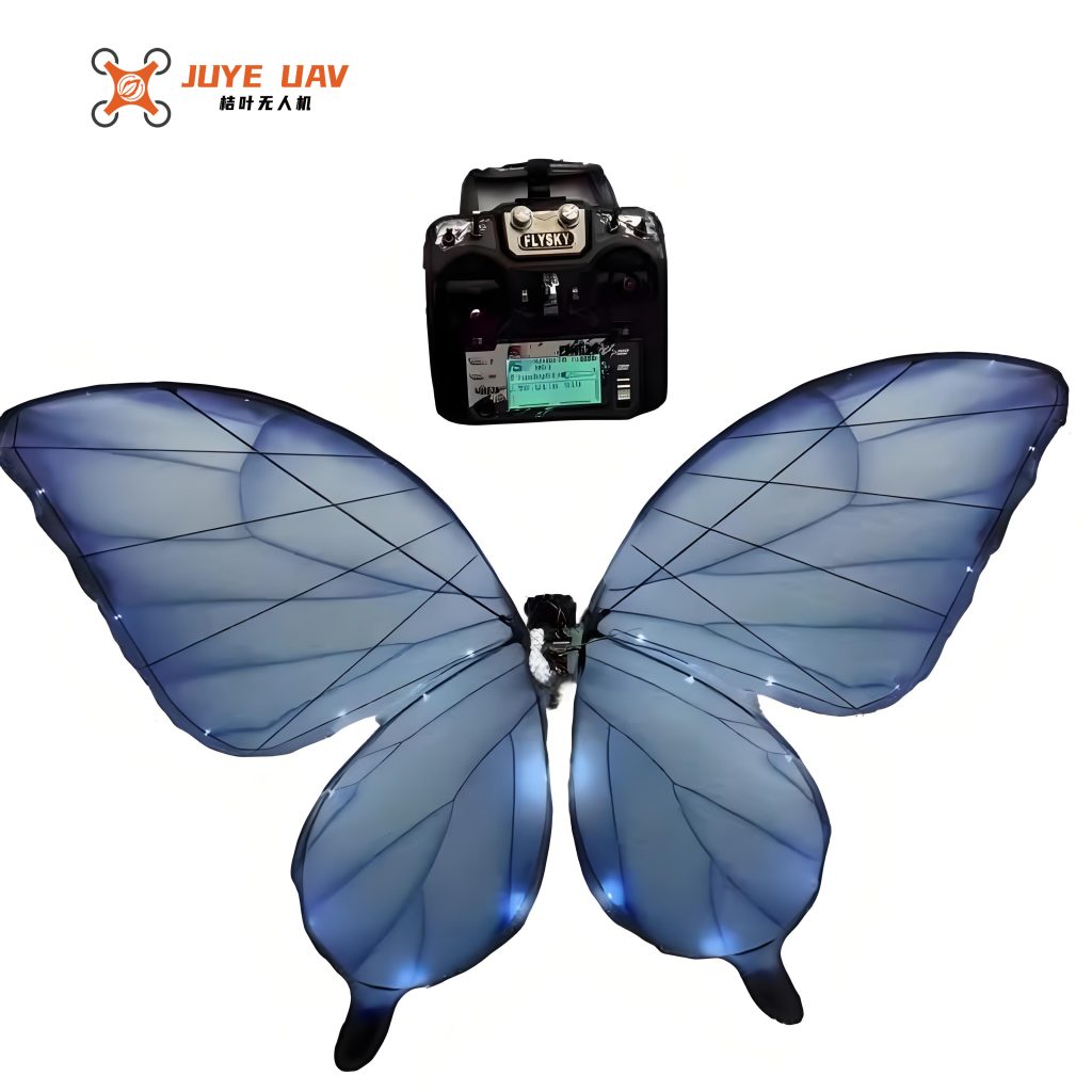
The wing design is the most critical biomimetic element. Butterflies possess two pairs of membranous wings whose complex venation provides structural support while allowing significant passive deformation—a key contributor to their aerodynamic efficiency. Our drone replicates this using a flexible wing architecture. The wing skeleton, mimicking the fractal pattern of butterfly venation, is constructed from 0.8mm diameter high-strength carbon fiber rods. This creates a lightweight yet resilient frame capable of elastic deformation during flapping cycles. The membrane is formed from P31n kite fabric, a material selected for its high tensile strength, durability, and minimal mass. The completed wing assembly features a main wing and a smaller forewing, analogous to the biological counterpart. The specifications for the primary structural and wing materials are summarized in Table 1.
| Component | Material | Key Property | Dimension / Specification |
|---|---|---|---|
| Central Boom | Carbon Fiber | High Stiffness, Low Density | Diameter: 3 mm |
| Wing Frame | Carbon Fiber Rod | High Strength, Flexibility | Diameter: 0.8 mm |
| Wing Membrane | P31n Kite Fabric | High Tensile Strength, Lightweight | Thickness: ~0.05 mm |
| Servo Housing | PLA (3D Printed) | Lightweight, Customizable Geometry | – |
| Overall Drone | – | Total Mass | 30 g (including battery) |
| Wingspan | – | – | 41.4 cm |
High-Performance Actuation System
A pivotal innovation in this flying butterfly drone is its actuation strategy. We abandon complex linkage and gear systems in favor of a direct-drive configuration using two high-performance micro digital servos (model: AF D30T-3.3-MG). Each servo is directly coupled to the root of one wing, enabling independent and precise control over each wing’s motion. This approach significantly reduces mechanical complexity, minimizes backlash, and improves overall efficiency and dynamic response.
The selected servo is a marvel of miniaturization. Constructed with a magnesium-aluminum alloy casing, it weighs only 3.3 grams. Its core delivers a stall torque of 0.18 N·m at 7.4V, with a peak torque capability of 0.25 N·m. Most critically, it exhibits an ultra-fast response time, capable of moving 60 degrees in just 0.06 seconds. This performance is essential for generating the high-frequency flapping necessary for sustained flight. The key specifications of the servo are detailed in Table 2.
| Parameter | Value | Unit |
|---|---|---|
| Mass | 3.3 | g |
| Dimensions (LxWxH) | 23.2 x 12.0 x 29.0 | mm |
| Operating Voltage | 7.4 | V |
| Stall Torque (@7.4V) | 0.18 | N·m |
| Peak Torque | 0.25 | N·m |
| Speed (60° travel) | 0.06 | s |
| Power Density | ~0.22 | W/g |
The kinematics of the flapping wing can be modeled based on the servo’s angular output. The instantaneous angular position of the wing, \(\theta(t)\), is directly controlled by the servo’s Pulse Width Modulation (PWM) input signal. For a symmetric flapping cycle, the motion can be approximated by a sinusoidal function:
$$ \theta(t) = \theta_{mid} + \theta_{amp} \cdot \sin(2\pi f t) $$
where \(\theta_{mid}\) is the mid-stroke angle (often set for optimal angle of attack), \(\theta_{amp}\) is the flapping amplitude (half of the total stroke angle), and \(f\) is the flapping frequency in Hz. The dual-servo system allows us to introduce a phase difference \(\phi\) between the left and right wings for turning maneuvers:
$$ \theta_L(t) = \theta_{mid} + \theta_{amp} \cdot \sin(2\pi f t + \phi) $$
$$ \theta_R(t) = \theta_{mid} + \theta_{amp} \cdot \sin(2\pi f t – \phi) $$
Furthermore, differential amplitude control can be applied for roll and yaw control, where \(\theta_{amp,L} \neq \theta_{amp,R}\).
Integrated Control System Architecture
The brain of the flying butterfly drone is a compact, multi-layer Printed Circuit Board (PCB) hosting a 2.4GHz RF communication module and power management units. The control algorithms are executed on an Arduino-compatible microcontroller. The system receives commands from a standard 10-channel remote controller via the nRF24L01+ transceiver.
The core flight control logic maps the incoming PWM signals from the transmitter to specific flight parameters for the twin servos. This mapping is implemented through a highly optimized function that generates a smooth, periodic control signal. The primary control channels and their mappings are as follows:
- Channel 1 (Aileron/Elevon): Maps to yaw/roll correction offset.
- Channel 2 (Elevator): Controls the mid-stroke angle (\(\theta_{mid}\)), affecting lift and pitch.
- Channel 3 (Throttle): Directly controls the flapping frequency (\(f\)).
- Channel 4 (Rudder): Introduces the differential phase (\(\phi\)) or amplitude for turning.
- Channel 5 (Aux 1): Sets the primary flapping amplitude (\(\theta_{amp}\)).
The mathematical implementation within the control loop for each servo’s output pulse width \(P(t)\) is a modified cosine function for computational efficiency:
$$ P(t) = S \pm (A \pm \Delta) \cdot \cos(\omega t) $$
Here, \(S\) is the servo’s neutral position pulse width (corresponding to \(\theta_{mid}\)), \(A\) is the base amplitude modulation value, \(\Delta\) is the differential turning input, and \(\omega\) is the angular velocity derived from the commanded flapping frequency. The variable \(t\) is controlled via a discrete loop counter \(i\), creating a stepped waveform that approximates the cosine function, reducing computational load on the microcontroller. The system continuously monitors the input channels and updates the servo commands in real-time, enabling stable hovering, forward flight, and controlled turns for the flying butterfly drone.
| Control Channel | Function | Mapped Parameter | Typical Target Range |
|---|---|---|---|
| Ch1 | Yaw/Roll | Differential Offset (\(\Delta\)) | -200 to +200 µs |
| Ch2 | Lift/Pitch | Neutral Position (S) | -250 to +250 µs |
| Ch3 | Thrust | Flapping Period (1/f) | 3500 to 10000 µs |
| Ch4 | Differential Turn | Phase/Amplitude Diff. | -100 to +100 µs |
| Ch5 | Amplitude | Flapping Amplitude (A) | 400 to 700 µs |
Prototype Testing and Performance Evaluation
The finalized prototype of the bio-inspired flying butterfly drone was assembled and subjected to comprehensive flight tests. The integrated system, powered by a 7.4V, 200mAh lithium-polymer battery, achieved its target specifications with a total mass of 30 grams and a wingspan of 41.4 cm.
In controlled indoor flight tests, the drone demonstrated stable flight capabilities. The flapping frequency was tunable between 8 Hz and 12 Hz, with optimal lift and forward thrust generated near 10 Hz. The direct-drive servo system proved highly responsive, allowing for rapid adjustments in wing kinematics. The drone successfully executed basic flight maneuvers including takeoff, level flight, and coordinated turns using the differential control strategy. The battery provided a consistent flight endurance of approximately 4.5 minutes per charge. Key performance metrics from the prototype testing are consolidated in Table 4.
| Performance Metric | Measured Value | Notes |
|---|---|---|
| Total Mass | 30 g | Including battery and all electronics |
| Wingspan | 41.4 cm | |
| Operational Flapping Frequency | 8 – 12 Hz | Stable flight at ~10 Hz |
| Flight Endurance | ~4.5 minutes | With 7.4V 200mAh Li-Po battery |
| Control Latency | < 20 ms | From command to servo response |
| Primary Flight Modes Demonstrated | Hover, Level Flight, Turning |
Aerodynamic Considerations and Future Directions
The flight of the flying butterfly drone relies on unsteady aerodynamic mechanisms. The primary forces are generated during the downstroke, where a combination of translational lift, delayed stall due to leading-edge vortices (LEVs), and wing rotation contribute to net lift and thrust. The flexibility of the P31n membrane and the carbon fiber frame allows for passive cambering and twist, which likely enhances aerodynamic efficiency by optimizing the effective angle of attack along the wing span throughout the stroke. While a full quantitative aerodynamic analysis is beyond this design overview, the successful flight validates the empirical effectiveness of the chosen bio-inspired kinematics and lightweight structure.
Future developments for this class of flying butterfly drone are directed towards enhanced autonomy and performance. Immediate improvements include the integration of miniature inertial measurement units (IMUs) and barometers to enable attitude stabilization and altitude hold via closed-loop feedback control. Research into advanced materials, such as electroactive polymers for active wing morphing, could yield even greater aerodynamic control authority. Furthermore, optimizing the wing shape and flexibility profile through coupled computational fluid dynamics and structural analysis presents a significant opportunity to increase lift-to-power ratios, thereby extending flight time. The integration of tiny solar cells onto the wing membrane for in-flight energy harvesting is another promising avenue for sustainable micro-air vehicle operation.
In conclusion, the design and successful demonstration of this bio-inspired flapping-wing drone validate a streamlined approach integrating biomimetic principles with advanced lightweight materials and high-performance direct-drive actuation. This flying butterfly drone platform establishes a foundation for future research into agile micro aerial vehicles, with potential applications in environmental monitoring, confined space exploration, and swarm robotics.