
The “chimney effect” inherent to high-rise buildings presents formidable challenges in firefighting, characterized by immense destructive power, high containment difficulty, and multiple pathways for fire spread. Conventional firefighting equipment, such as ladder trucks, grapple with limitations including restricted maximum reach, obstructed access, constrained deployment environments, and prolonged setup times. Consequently, firefighting and rescue operations in high-rise structures remain a persistent global challenge, imposing significant demands on fire and rescue services.
In this context, the emergence of unmanned aerial vehicle (UAV) technology offers a promising supplementary tool. While surveillance-type fire UAVs provide crucial situational awareness,灭火型 (fire-suppression) fire UAVs carry the potential for direct intervention. Typically equipped with water, foam, powder, or extinguishing projectiles, these systems are designed to execute aerial firefighting tasks. Their standard operational method involves horizontal discharge or projectile deployment towards building apertures, with effective ranges varying between 5 to 15 meters, aiming to suppress internal fires by introducing extinguishing agents through windows.
The conventional operational paradigm for such fire UAVs often relies on manual, line-of-sight (LOS) remote control. An operator visually aligns the UAV’s nozzle with the target, using the live video feed from an onboard camera as a reference. However, in the complex, high-altitude environment of a high-rise fire, maintaining accurate LOS and precise manual alignment becomes exceedingly difficult and operator-dependent. This challenge is exacerbated when the operational zone falls beyond direct visual range, leading to potentially critical targeting inaccuracies. Therefore, developing a remote-controlled, precision-aiming methodology is imperative to enhance the accuracy and reliability of fire UAV suppression missions. This document details the research and implementation of a Ground Control Station (GCS)-based assisted aiming method designed to address this core operational gap.
System Architecture of the Firefighting UAV Platform
The development and validation of the assisted aiming method are based on a dedicated heavy-lift fire UAV platform. This system is architected into three primary subsystems: the Airframe Structure, the Onboard Avionics System, and the Ground Control Station (GCS).
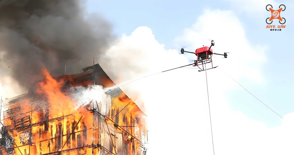
The Airframe Structure provides the foundational platform, hosting the extinguishing agent payload (up to 100 kg of water/foam), the discharge mechanism (fixed forward-facing nozzle), and serving as the mounting point for all other subsystems, ensuring structural integrity and balanced load distribution.
The Onboard Avionics System constitutes the core operational intelligence of the fire UAV and includes several integrated modules:
| Subsystem | Key Components | Primary Function |
|---|---|---|
| Flight Control System | Flight Controller, IMU, GPS, Barometer | Processes flight commands, fuses sensor data (attitude, position, velocity), and maintains stable flight and position hold. |
| Environmental Perception | Forward-facing Visible Light Camera, Multi-directional LiDAR sensors | Camera provides real-time video for situational awareness and aiming. LiDAR detects obstacles (e.g., building facades) within a ~100m range, providing critical distance data. |
| Propulsion & Power | Multi-rotor propulsion units, High-capacity Li-ion Battery Packs | Provides lift, maneuvering thrust, and electrical power for all onboard systems. |
| Communication Link | 4G LTE/5G Cellular Modem | Establishes a robust data link between the fire UAV and the GCS for telemetry uplink and video/data downlink. |
| Mission Payload | Extinguishing Agent Tank, Pump/Valve, Nozzle, Breaching Projectiles | Stores and delivers the extinguishing agent upon command. |
The Ground Control Station (GCS) is the human-machine interface for mission command. It runs specialized software that presents a synthesized operational view, displaying real-time flight data, vehicle location on a map, LiDAR point clouds representing obstacle contours, and the live video feed from the fire UAV‘s camera. It is here that the assisted aiming algorithm is implemented, allowing the operator to command the UAV with high precision through intuitive interactions.
Principle and Computational Workflow of Assisted Aiming
The core innovation lies in translating a simple operator action—clicking on a target within the video feed—into precise, automated UAV positional adjustments. The method leverages camera projection geometry and fusion with LiDAR-derived spatial data.
1. Operational Preliminaries: Positioning and Scene Mapping
Deployed from strategic locations, the fire UAV autonomously navigates to the fire scene. The operator manually pilots it to a stand-off position roughly 20-30 meters from the building facade at the approximate height of the fire. The LiDAR data is streamed to the GCS and rendered as a point cloud. The operator then uses a drawing tool within the GCS interface to fit a line segment to the point cloud, digitally defining the building’s “facade reference line.” This geometric primitive is crucial for subsequent calculations.
2. Core Calculation: Deriving Target Angles from Screen Click
With the assisted aiming mode activated, the UAV’s camera is fixed in a forward-facing orientation aligned with the discharge nozzle. When the operator clicks on a specific pixel M (X’, Y’) within the video feed (representing the fire point), the GCS calculates the angular offset of this point from the camera’s central boresight.
Given the known camera properties—horizontal and vertical Field of View (FOV) angles and image resolution in pixels—the angular deviations are computed. Let the image center be O, horizontal FOV be $$\angle FOV_x$$, vertical FOV be $$\angle FOV_y$$, horizontal resolution be $$P_x$$ pixels, and vertical resolution be $$P_y$$ pixels. The pixel offsets from the center are $$X’$$ and $$Y’$$.
The horizontal and vertical angular offsets $$\angle M_{horizontal}$$ and $$\angle M_{vertical}$$ of point M from the image center are:
$$ \angle M_{horizontal} = \frac{X’}{P_x / 2} \cdot \left( \frac{\angle FOV_x}{2} \right) $$
$$ \angle M_{vertical} = \frac{Y’}{P_y / 2} \cdot \left( \frac{\angle FOV_y}{2} \right) $$
Consequently, the angles between the camera’s central axis (aligned with UAV heading) and the line of sight to the target point are:
$$ \angle C_{horizontal} = 90^\circ – \angle M_{horizontal} = 90^\circ – \left[ \frac{X’}{P_x / 2} \cdot \left( \frac{\angle FOV_x}{2} \right) \right] $$
$$ \angle C_{vertical} = 90^\circ – \angle M_{vertical} = 90^\circ – \left[ \frac{Y’}{P_y / 2} \cdot \left( \frac{\angle FOV_y}{2} \right) \right] $$
$$\angle C_{horizontal}$$ is the critical azimuth angle used for lateral positioning.
3. Data Fusion: Calculating Target Distance in World Coordinates
Knowing the angle is insufficient; the distance to the target is also required. This is achieved by fusing the angle data with the geometric model of the facade. The facade reference line drawn by the operator has a known equation in the GCS’s local coordinate system (aligned with the UAV’s initial position as the origin):
$$ L_1: A_1x + B_1y + C_1 = 0 $$
The line from the UAV to the target point, defined by $$\angle C_{horizontal}$$, can also be expressed (where $$m$$ is derived from the angle):
$$ L_2: y = m \cdot x \quad \text{or} \quad A_2x + B_2y = 0 $$
Solving this system of equations for the intersection point $$T(x_T, y_T)$$ gives the coordinates of the target relative to the UAV. The horizontal distance $$S$$ from the UAV to the target is then:
$$ S = \sqrt{x_T^2 + y_T^2} $$
4. Command Generation: Computing the Optimal Firefighting Position
The final step is to command the UAV to move to the optimal discharge point. This point is located along the normal (perpendicular) line to the facade, passing through the target, at a predefined optimal operational range $$D$$ (e.g., 10 meters, based on nozzle performance). Using the calculated distance $$S$$, the desired stand-off distance $$D$$, and the angle $$\angle C_{horizontal}$$, the required UAV movement vector is derived via trigonometric relationships within the formed triangle.
The necessary displacement $$( \Delta x, \Delta y )$$ in the UAV’s horizontal plane is calculated. This displacement command, along with any required altitude adjustment based on $$\angle C_{vertical}$$, is sent via the 4G link to the flight controller. The fire UAV then executes an automated maneuver to the computed coordinates and aligns its yaw to face perpendicularly towards the building facade.
| Step | Operator Action / System Input | Key Calculation | Output |
|---|---|---|---|
| 1. Scene Mapping | Interprets LiDAR point cloud to draw facade line. | Defines geometric constraint ($$L_1$$). | Facade reference line in GCS coordinates. |
| 2. Target Designation | Clicks on fire point in video feed (Pixel M). | $$ \angle C_{horizontal} = 90^\circ – \left[ \frac{X’}{P_x / 2} \cdot \left( \frac{\angle FOV_x}{2} \right) \right] $$ | Bearing to target from UAV heading. |
| 3. Distance Resolution | System uses facade line ($$L_1$$) and angle ($$ \angle C $$). | Solve intersection of $$L_1$$ and $$L_2$$. Compute $$S = \sqrt{x_T^2 + y_T^2}$$. | Horizontal distance (S) to target point. |
| 4. Position Computation | System uses $$S$$, $$D$$ (optimal range), and $$ \angle C $$. | Trigonometric solution for the movement legs to the point on the facade normal at distance D. | Displacement command $$( \Delta x, \Delta y )$$. |
| 5. Execution | System sends command to fire UAV flight controller. | Automatic waypoint navigation and yaw alignment. | UAV repositioned to optimal firing point. |
Validation and Performance Analysis
The proposed GCS-assisted aiming method was integrated into the described heavy-lift fire UAV platform (model EH216-F) and subjected to field trials simulating high-rise fire scenarios. The fire UAV was loaded with 100 kg of water-based extinguishing agent.
The trials confirmed the robustness of the system architecture and the effectiveness of the aiming algorithm. The key performance metric was the adjustment time—the duration from the operator’s final target designation click to the fire UAV stabilizing at the computed optimal firing position. Statistical analysis from multiple test runs yielded an average adjustment time of approximately 15 seconds.
| Test Metric | Result | Implication |
|---|---|---|
| Average Adjustment Time | ~15 seconds | Dramatically faster than iterative manual positioning, allowing quicker agent application. |
| Aiming Accuracy | Successful agent coverage of target window area. | The method reliably positions the UAV for effective nozzle coverage. |
| Operator Workload | Significantly reduced | Complex spatial reasoning and stick control replaced by simple point-and-click interface. |
| Non-Line-of-Sight Capability | Fully enabled | Precision targeting no longer dependent on operator’s direct visual contact with the UAV. |
This performance enhancement is critical in firefighting, where every second counts. The method effectively decouples aiming precision from operator skill in manual flight control, standardizing and accelerating the most delicate phase of the fire UAV‘s mission. The integration of environmental perception (LiDAR) with intuitive human input (video click) and automated flight control creates a synergistic system that enhances both the safety and operational efficacy of the fire UAV platform.
Conclusion
This work addresses a fundamental operational challenge in employing fire UAVs for high-rise building fire suppression: achieving reliable, precise targeting beyond visual line of sight and independent of highly variable manual piloting skill. The GCS-based assisted aiming method presented here provides an effective solution. By leveraging standard camera projection models, fusing real-time LiDAR mapping data, and translating intuitive operator inputs into automated flight commands, the system enables accurate placement of the fire UAV at the optimal stand-off point for discharge.
The field validation confirms the practical utility of the method, with the system achieving target repositioning in an average of 15 seconds. This represents a substantial improvement over purely manual techniques, reducing operator cognitive load, minimizing engagement time, and increasing the repeatability and reliability of fire UAV suppression missions. This methodological framework establishes a foundation for more advanced automation in aerial firefighting, paving the way for intelligent fire UAV systems that can act as force multipliers for ground-based firefighting teams confronting the persistent challenge of high-rise fires.