In modern infrastructure maintenance, the detection of cracks on high slopes is a critical task, as these cracks serve as key indicators of potential slope failure and geological hazards. Traditional manual inspection methods are often inefficient, time-consuming, and pose significant safety risks for personnel working on steep terrains. To address these challenges, I propose the integration of UAV drone technology into high-slope crack detection. UAV drones, or unmanned aerial vehicles, offer a revolutionary approach by enabling rapid, non-contact, and high-resolution imaging of slopes, thereby enhancing detection accuracy and operational safety. This article delves into the comprehensive application of UAV drones for crack detection on high slopes, covering aspects from flight planning and image acquisition to advanced image processing and crack parameter quantification. By leveraging UAV drones, we can overcome the limitations of conventional methods and pave the way for automated, intelligent slope monitoring systems.
The use of UAV drones in geotechnical engineering has gained momentum due to their flexibility, cost-effectiveness, and ability to access hazardous areas. For high-slope crack detection, UAV drones equipped with high-resolution cameras can capture detailed imagery, which is then processed using computer vision algorithms to extract crack features. I will explore this process in detail, emphasizing the design of photography schemes, key parameter controls, and image processing techniques. Additionally, I will present methodologies for calculating crack dimensions such as area, length, and width, and validate the results through comparative analysis. Throughout this discussion, the term “UAV drones” will be frequently highlighted to underscore their pivotal role in this application. The goal is to provide a thorough technical framework that can be adopted for similar engineering projects worldwide.
To illustrate the practical implementation, I consider a typical high-slope scenario along a highway in a mountainous region. This slope, characterized by steep gradients and complex geology, presents common challenges such as rock weathering, joint development, and erosion from heavy rainfall. The slope is designed with multiple tiers, each with varying inclinations and protective measures like anchor frames and vegetation. Such slopes are prone to cracking due to factors like water infiltration, seismic activity, and structural stress. UAV drones are deployed here to conduct a comprehensive survey, capturing imagery that reveals surface cracks imperceptible to the naked eye from ground level. The environment features low mountain丘陵 topography, with bedrock composed of tuff sandstone and limestone, and a climate marked by abundant precipitation, which exacerbates slope instability. By using UAV drones, we can efficiently assess these conditions without endangering human inspectors.
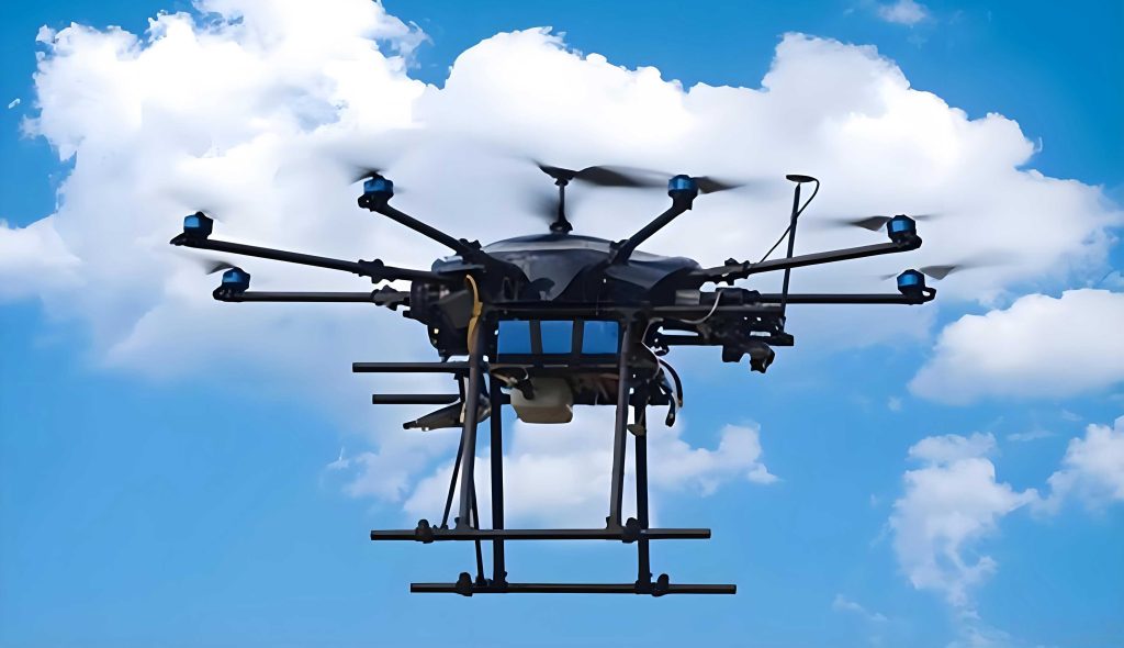
The design of the UAV drone photography scheme is fundamental to obtaining high-quality images for crack detection. I utilize a rotary-wing UAV drone model, similar to the DJI Matrice series, equipped with RTK (Real-Time Kinematic) positioning for enhanced georeferencing accuracy. The photography scheme involves two main aspects: the selection of photography modes and the control of key parameters. For slopes with minimal obstructions, I recommend nadir (vertical) photography, where the UAV drone captures images directly downward. In areas obscured by rocks, vegetation, or other features, oblique photography at multiple angles is employed to ensure complete coverage of crack morphology. This adaptive approach, facilitated by UAV drones, allows for comprehensive data collection even in complex terrains.
Key parameters must be rigorously controlled to optimize image quality. These include overlap, ground sample distance (GSD), shutter speed, and ISO sensitivity. Overlap, both along-track and across-track, ensures sufficient image redundancy for photogrammetric processing. Based on engineering practice, I set the along-track overlap ($q_x$) and across-track overlap ($q_y$) to be at least 80% each. The formulas for calculating these are:
$$q_x = \frac{P_x}{L_x} \times 100\%$$
$$q_y = \frac{P_y}{L_y} \times 100\%$$
where $P_x$ and $P_y$ represent the overlapping edge lengths in the along-track and across-track directions, respectively, and $L_x$ and $L_y$ are the corresponding image frame dimensions. UAV drones enable precise control of these overlaps through automated flight planning software.
Ground sample distance (GSD) determines the spatial resolution of the imagery, affecting the ability to detect fine cracks. It is calculated as:
$$GSD = \frac{H \cdot l}{10 \cdot f}$$
where $H$ is the flight altitude of the UAV drone, $l$ is the pixel size of the camera sensor, and $f$ is the focal length of the lens. For high-slope crack detection, I typically aim for a GSD of less than 1 cm to capture细微 cracks. UAV drones allow adjustment of $H$ to achieve the desired GSD, balancing detail with coverage area.
Shutter speed and ISO sensitivity are crucial for image clarity, especially in varying lighting conditions on slopes. I advise using a shutter speed of 1/125 seconds to minimize motion blur, and an ISO of 100 to reduce noise. UAV drones with advanced cameras can automatically adjust these settings, but manual control is preferred for consistency. The following table summarizes the key photography parameters for UAV drone-based crack detection:
| Parameter | Recommended Value | Description |
|---|---|---|
| Along-track Overlap ($q_x$) | ≥ 80% | Ensures continuous coverage along flight path |
| Across-track Overlap ($q_y$) | ≥ 80% | Ensures overlap between adjacent flight lines |
| Ground Sample Distance (GSD) | < 1 cm | Determines image resolution; smaller GSD for finer cracks |
| Shutter Speed | 1/125 s | Prevents motion blur from UAV drone movement |
| ISO Sensitivity | 100 | Minimizes image noise in good lighting |
Once imagery is acquired by UAV drones, it undergoes a series of preprocessing steps to prepare for crack analysis. The raw images often contain distortions and noise that must be corrected to ensure accurate measurements. The first step is distortion correction, which addresses lens-induced geometric errors. I employ the Brown-Conrady model, commonly used in photogrammetry, to correct radial and tangential distortions. The correction formulas are:
$$\begin{cases}
x_0 = x (1 + k_1 r^2 + k_2 r^4 + k_3 r^6) + [2p_1 y + p_2 (r^2 + 2x^2)] \\
y_0 = y (1 + k_1 r^2 + k_2 r^4 + k_3 r^6) + [2p_1 x + p_2 (r^2 + 2y^2)]
\end{cases}$$
where $(x_0, y_0)$ are the original coordinates of a distorted point, $(x, y)$ are the corrected coordinates, $r$ is the radial distance from the image center, and $k_1, k_2, k_3, p_1, p_2$ are distortion parameters obtained through camera calibration. For UAV drone cameras, these parameters are typically calibrated using methods like the Zhang’s method, yielding values such as $k_1 = -0.46867$, $k_2 = 0.27536$, and $k_3 = -0.00327$, with $p_1$ and $p_2$ often negligible for high-quality lenses.
After distortion correction, images are converted to grayscale to simplify processing. Various grayscale methods exist, each with distinct characteristics. I prefer the weighted average method, which accounts for human visual perception by assigning different weights to red, green, and blue channels. For crack detection, this method preserves brightness细节 better than alternatives. The following table compares common grayscale techniques:
| Method | Algorithm | Application Notes |
|---|---|---|
| Weighted Average | $I = 0.299R + 0.587G + 0.114B$ | Retains luminance details; suitable for crack images from UAV drones |
| Maximum Value | $I = \max(R, G, B)$ | Highlights bright areas; may lose crack details in shadows |
| Minimum Value | $I = \min(R, G, B)$ | Highlights dark areas; may exaggerate noise |
Next, image denoising is performed to remove artifacts that could interfere with crack identification. I evaluate several filtering methods and find that mean filtering offers a balance between noise reduction and computational efficiency for UAV drone imagery. However, in cases where crack edges are critical, Gaussian filtering may be preferred. The table below outlines denoising options:
| Filter Type | Algorithm | Pros and Cons |
|---|---|---|
| Mean Filter | Replaces pixel with neighborhood average | Fast and simple; may blur crack edges |
| Gaussian Filter | Weighted average using Gaussian kernel | Preserves edges better; more computationally intensive |
| Median Filter | Replaces pixel with neighborhood median | Effective for salt-and-pepper noise; less suitable for Gaussian noise |
For high-slope crack detection, I often use mean filtering due to its speed, as UAV drones can generate large image datasets requiring efficient processing.
Image segmentation isolates crack regions from the background, creating a binary image where cracks are represented by pixel values of 1 and non-crack areas by 0. I utilize Otsu’s method, which maximizes the inter-class variance to determine an optimal threshold $T$. The process involves iterating through possible threshold values and computing the variance between foreground (crack) and background classes. The threshold that maximizes $\sigma^2$ is selected:
$$\sigma^2 = \omega_1 \omega_2 (\mu_1 – \mu_2)^2$$
where $\omega_1$ and $\omega_2$ are the probabilities of the two classes, and $\mu_1$ and $\mu_2$ are their mean intensities. This method works well with UAV drone images, as it adapts to varying lighting conditions on slopes.
With binary images obtained, crack parameters can be quantified. Crack area ($S$) is calculated by summing all pixels with value 1:
$$S = \sum_{i=1}^{N} I(i), \quad \text{where } I(i) = 1 \text{ for crack pixels}$$
This simple pixel-counting approach, facilitated by UAV drone imagery, provides an accurate measure of crack extent.
Crack length requires thinning the binary image to a one-pixel-wide skeleton. I apply a morphological thinning algorithm that iteratively removes boundary pixels while preserving connectivity. For a pixel $p$ with 8-neighborhood values $p_i$ (i=1 to 8), deletion conditions include $2 \leq \sum p_i \leq 6$ and a single transition from 0 to 1 in the clockwise neighborhood. This yields a skeleton from which length is computed by tracing contiguous pixels. UAV drones enable high-resolution images that support precise skeletonization.
Crack width is determined using two methods: erosion-based and center-skeleton perpendicular line methods. The erosion method involves repeatedly applying a circular structuring element of radius $r$ to erode the crack边界. After $n$ erosions, the maximum width $W_{\text{max}}$ is estimated as $2nr$. However, this method can underestimate width for irregular cracks. The center-skeleton method is more accurate: first, the crack centerline is fitted using least squares regression on edge pixel coordinates. Then, perpendicular lines are drawn to this centerline at intervals, and the distance between intersections with crack edges gives the local width $B$. For a crack with upper edge points $(x_u, y_u)$ and lower edge points $(x_l, y_l)$, the centerline is represented as $y = mx + c$, and perpendicular slopes are $-1/m$. The width at a point $(x_c, y_c)$ on the centerline is calculated as:
$$B = \sqrt{(x_{u} – x_{l})^2 + (y_{u} – y_{l})^2}$$
where $(x_{u}, y_{u})$ and $(x_{l}, y_{l})$ are the intersection points. This method accounts for sub-pixel precision, enhancing the accuracy of UAV drone-based measurements.
To validate the UAV drone approach, I compare results with manual measurements from the same slope. The table below presents a sample comparison for a detected crack, showing parameters like area, length, average width, and maximum width from both methods. Relative errors are computed to assess accuracy:
| Detection Metric | UAV Drone Value | Manual Value | Relative Error (%) |
|---|---|---|---|
| Area (cm²) | 6.40 | 6.25 | 2.3 |
| Length (cm) | 18.5 | 18.2 | 1.6 |
| Average Width (cm) | 0.35 | 0.34 | 2.9 |
| Max Width (Erosion) (cm) | 1.28 | 1.22 | 4.7 |
| Max Width (Center-Skeleton) (cm) | 1.26 | 1.22 | 3.2 |
The relative error is calculated as:
$$\text{Relative Error} = \left| \frac{\text{UAV Drone Value} – \text{Manual Value}}{\text{UAV Drone Value}} \right| \times 100\%$$
All errors are below 5%, demonstrating that UAV drones meet engineering accuracy requirements for high-slope crack detection. This validation underscores the reliability of UAV drone technology in geotechnical applications.
Beyond basic parameters, UAV drones facilitate advanced analyses such as crack orientation, density, and temporal monitoring. By conducting repeat surveys with UAV drones, we can track crack propagation over time, assessing slope stability and predicting failure risks. Integration with GIS (Geographic Information Systems) allows for spatial mapping of cracks across large slope areas, enabling prioritized maintenance. Moreover, machine learning algorithms can be applied to UAV drone imagery for automated crack classification and severity assessment, further reducing human intervention. The use of UAV drones in these contexts enhances data-driven decision-making for slope management.
In terms of practical implementation, I recommend a workflow for UAV drone-based crack detection: (1) Pre-flight planning, including site assessment and parameter setting; (2) UAV drone deployment with real-time monitoring; (3) Image processing using the steps outlined; (4) Crack parameter extraction and validation; (5) Reporting and integration into maintenance systems. UAV drones should be equipped with high-precision GNSS and IMU sensors to geotag images accurately. Additionally, weather conditions must be considered—UAV drones perform best under calm winds and clear skies to ensure image quality.
The advantages of using UAV drones are manifold. They reduce inspection time from days to hours, minimize safety hazards, and provide consistent, objective data. For instance, on a high slope of 30 meters height, manual inspection might require scaffolding or rope access, whereas UAV drones can capture the entire slope in a single flight. Cost savings are also significant, as UAV drones lower labor costs and prevent downtime. Furthermore, the digital nature of UAV drone data allows for easy storage, sharing, and re-analysis, supporting long-term slope health monitoring.
However, challenges exist, such as regulatory restrictions on UAV drone flights, battery life limitations, and data processing demands. I suggest using UAV drones with extended battery capacities and automated flight software to overcome these. For data processing, cloud-based platforms can handle large datasets from UAV drones efficiently. Ongoing advancements in UAV drone technology, like AI-powered autopilots and multispectral cameras, will further enhance crack detection capabilities.
In conclusion, UAV drones represent a transformative tool for high-slope crack detection. Through meticulous photography scheme design, rigorous parameter control, and advanced image processing, UAV drones deliver accurate measurements of crack dimensions. The validation results confirm that UAV drone-derived data align closely with manual methods, with errors within acceptable limits. As UAV drone technology evolves, its integration with other sensing modalities (e.g., LiDAR, thermal cameras) will enable even more comprehensive slope assessments. I encourage widespread adoption of UAV drones in geotechnical engineering to improve safety, efficiency, and reliability in infrastructure monitoring. By leveraging UAV drones, we can proactively address slope hazards, ultimately protecting communities and assets from potential disasters.