The proliferation of unmanned aerial vehicles (UAVs), valued for their compact size, affordability, and operational flexibility, has introduced significant security challenges in urban environments. Incidents involving UAVs, such as collisions with infrastructure or uncontrolled descents, pose substantial risks to public safety and property. Consequently, the development of robust counter-UAV, or anti-drone, technologies has become a critical focus. Among various detection methods, electro-optical (EO) systems offer distinct advantages for urban anti-drone applications due to their passive nature, visual verification capability, and relatively lower cost. This paper presents a comprehensive analysis of an automatic image tracking system designed for urban low-altitude anti-drone operations, which integrates a novel fusion of the Discriminative Scale Space Tracking (DSST) and Kernelized Correlation Filter (KCF) algorithms to address the specific challenge of tracking “low, slow, and small” (LSS) UAVs.
1. System Architecture and Workflow
The proposed anti-drone tracking system is architected into two primary units: the Dual-light Image Acquisition Unit and the Display & Control Unit. This bifurcation separates the sensory and computational responsibilities, optimizing performance for real-time anti-drone tracking.
1.1 Hardware Composition
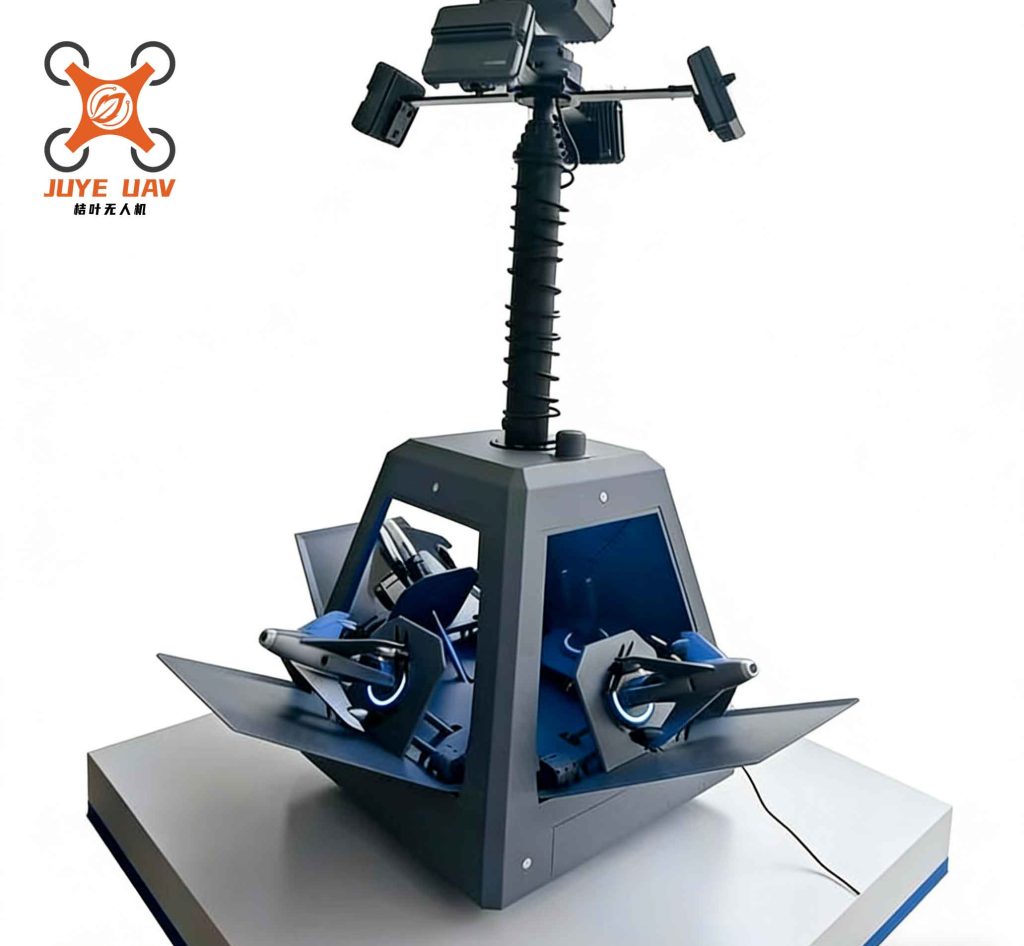
The Dual-light Image Acquisition Unit is centered on a pan-tilt-zoom (PTZ) gimbal camera system equipped with dual sensors. This configuration is pivotal for a reliable anti-drone system, ensuring operability across diverse lighting and weather conditions. A high-resolution visible-light camera handles daytime tracking, while an uncooled infrared thermal imager provides capability during nighttime or adverse weather, a common requirement for persistent anti-drone surveillance. The gimbal mechanism provides the necessary degrees of freedom for tracking agile aerial targets. The Display & Control Unit is implemented on a standard computing platform, responsible for the core image processing, execution of the tracking algorithm, calculation of gimbal control parameters, and the user interface. A high-speed Ethernet link facilitates real-time video streaming and command transmission between the units.
1.2 Operational Workflow
The system operates in two primary states: manual mode and automatic tracking mode. In automatic tracking mode, essential for autonomous anti-drone response, the workflow is a closed-loop process. The control unit ingests the Real-Time Streaming Protocol (RTSP) video feed. Upon successful initialization where a target UAV is selected (via manual designation or an external detection cue), the core tracking algorithm processes each frame. It predicts the target’s new positional and scale state based on the previous frame’s model. This estimated state is then fed into a dedicated PTZ control strategy module. This module calculates the precise pan, tilt, and zoom commands required to keep the target centered within the camera’s field of view (FOV). These commands are dispatched to the gimbal, physically slewing the cameras to maintain the track. This continuous perception-action cycle enables the system to follow a maneuvering drone effectively.
2. The Fusion DSST-KCF Tracking Algorithm
The core innovation of this anti-drone system lies in its visual tracking algorithm. While the standard KCF algorithm is renowned for its high speed using circulant matrices and the kernel trick, it lacks an inherent mechanism for scale adaptation. This is a critical flaw for anti-drone scenarios where the target’s apparent size can change dramatically as it moves toward or away from the sensor. The DSST algorithm excels at robust scale estimation but can be computationally heavier. Our fusion approach strategically combines their strengths to create a tracker that is both fast and scale-adaptive, ideal for LSS anti-drone tracking.
The algorithm maintains two independent correlation filters: a translation filter (from KCF) for locating the target and a scale filter (from DSST) for estimating its size. The process for each frame is: 1) Use the translation filter from the previous frame to locate the target in the new frame. 2) At this new location, apply the scale filter to determine the optimal target size. 3) Update both filters using the new position and scale with a learning rate, preparing for the next frame. This decoupled yet synergistic approach is key to our anti-drone tracker’s performance.
2.1 Target Translation Estimation via KCF
The translation filter treats tracking as a regression problem. A base image patch x of size M x N centered on the target is used to generate a vast number of synthetic training samples efficiently via cyclic shifts. This circulant structure is the engine of the algorithm’s speed. Each shifted sample xi has a corresponding label yi from a Gaussian function peaked at the target center. The goal is to find a function f(z) = ωTφ(z) that minimizes the ridge regression loss over all samples:
$$ \min_{\omega} \sum_i (f(x_i) – y_i)^2 + \lambda \|\omega\|^2 $$
where ω are the classifier parameters, φ denotes the mapping to a high-dimensional feature space (via the kernel trick), and λ is a regularization parameter. Using circulant matrix properties and the Fast Fourier Transform (FFT), the solution in the Fourier domain for the dual coefficients α becomes extremely efficient:
$$ \hat{\alpha} = \frac{\hat{y}}{\hat{k}^{xx} + \lambda} $$
Here, ̂ denotes the DFT, y is the label vector, and kxx is the kernel auto-correlation. For detection in a new frame, a patch z is cropped at the last position. The response map is calculated in the frequency domain as:
$$ \hat{f}(z) = \hat{k}^{xz} \odot \hat{\alpha} $$
where kxz is the kernel cross-correlation between the new patch and the base model x. The target’s new translation is found at the maximum of the inverse DFT of f(z). For robust anti-drone tracking, we employ HOG features within this framework.
2.2 Target Scale Estimation via DSST
To address scale variations critical in long-range anti-drone tracking, a separate one-dimensional scale filter is employed. Let the current target size be P x Q. A scale pyramid of S scales is constructed at the estimated translation:
$$ a^n P \times a^n Q, \quad n \in \left\{ -\left\lfloor \frac{S-1}{2} \right\rfloor, \dots, \left\lfloor \frac{S-1}{2} \right\rfloor \right\} $$
where a is a scale factor (e.g., 1.02). For each scale level n, a feature vector xn is extracted. The scale filter h is trained to produce a Gaussian response g peaked at the current scale. The optimal filter in the frequency domain is solved similarly:
$$ \min_{H} \sum_{j=1}^{t} \|\bar{X}_j H – G_j\|^2 + \lambda \|H\|^2 $$
leading to the solution per channel (simplified):
$$ H = \frac{\sum_{j=1}^{t} \bar{G}_j X_j}{\sum_{j=1}^{t} \bar{X}_j X_j + \lambda} $$
where the numerator A and denominator B are updated online:
$$ \begin{aligned}
A_{t} &= (1 – \eta) A_{t-1} + \eta \bar{G}_t X_t \\
B_{t} &= (1 – \eta) B_{t-1} + \eta \bar{X}_t X_t
\end{aligned} $$
Here, η is the learning rate. During detection, the scale response ys is computed for a new sample Z:
$$ \hat{y}^s = \frac{\hat{A} \hat{Z}}{\hat{B} + \lambda} $$
The scale corresponding to the maximum of ys is selected. This updated scale is then fed back to the translation filter in the next frame to extract image patches of the correct size, closing the scale adaptation loop. This fusion is what makes our anti-drone tracker resilient to target distance changes.
3. DSST-KCF-PTZ Integrated Control Strategy
Effective anti-drone tracking requires more than just a robust image algorithm; it necessitates tight coordination with the physical sensor platform. Our control strategy translates pixel-based tracking outputs into smooth and stable gimbal movements.
We define an image coordinate system with the origin at the top-left corner, the x-axis horizontal to the right, and the y-axis vertical downward. To prevent jittery, over-active gimbal movement that could disrupt the track, the FOV is partitioned into three concentric constraint zones: a central dead-zone (C), a medium-speed zone (B), and a high-speed zone (A). The gimbal’s pan and tilt speeds are modulated based on which zone the target’s centroid occupies and its velocity within the image.
3.1 Directional Control Logic
Let the image resolution be (W, H) and the target’s centroid be at (xg, yg). The zone boundaries are defined as multiples of ΔW = W/5 and ΔH = H/5. The directional control logic is deterministic, as summarized in the following table.
| Target Horizontal Zone | Target Vertical Zone | Gimbal Movement Direction |
|---|---|---|
| xg < 2ΔW (Left) | yg < 2ΔH (Top) | Pan Left, Tilt Up |
| 2ΔH ≤ yg ≤ 3ΔH (Center-V) | Pan Left | |
| yg > 3ΔH (Bottom) | Pan Left, Tilt Down | |
| 2ΔW ≤ xg ≤ 3ΔW (Center-H) | yg < 2ΔH (Top) | Tilt Up |
| 2ΔH ≤ yg ≤ 3ΔH (Center-V) | No Movement | |
| yg > 3ΔH (Bottom) | Tilt Down | |
| xg > 3ΔW (Right) | yg < 2ΔH (Top) | Pan Right, Tilt Up |
| 2ΔH ≤ yg ≤ 3ΔH (Center-V) | Pan Right | |
| yg > 3ΔH (Bottom) | Pan Right, Tilt Down |
3.2 Speed Modulation
The base speed Vq for zone q (where VA > VB > VC) is adaptively modulated by the target’s pixel velocity to achieve predictive tracking. For the horizontal component: let Δx = xg(t) - xg(t-1) be the inter-frame pixel displacement. The pixel velocity is Vpix = Δx / ΔT, where ΔT is the frame interval. A direction flag f is set to +1 if the target is to the right of center, else -1. The final commanded gimbal speed Vcmd is:
$$ V_{cmd} = V_q + \theta \cdot f \cdot V_{pix} $$
where θ is a damping factor that prevents overshoot and ensures smooth motion, a crucial aspect for maintaining a clear anti-drone track. Vertical speed is computed analogously.
3.3 Auto-Zoom (Focus) Control
Maintaining an optimal target size in the image is vital for reliable anti-drone tracking. If the target is too small, feature extraction suffers; if too large, it risks exiting the FOV during motion. Let the tracking bounding box area be p1 and the full image area be p2. The occupancy ratio is σ = p1 / p2. The system maintains a desired range [σmin, σmax]. Periodically, if σ < σmin, the camera zooms in; if σ > σmax, it zooms out. This keeps the target at a nearly constant pixel size, significantly aiding the stability of the DSST scale filter and the overall anti-drone mission.
4. Algorithmic and System Performance Evaluation
The performance of the fused DSST-KCF algorithm and the integrated anti-drone system was rigorously evaluated through benchmark tests and real-world field trials.
4.1 Algorithm Benchmarking
The algorithm was tested on the OTB100 dataset and a custom anti-drone UAV dataset. Performance was measured using standard one-pass evaluation (OPE) metrics: Precision (the percentage of frames where the center location error is below a threshold, typically 20 pixels) and Success Rate (the percentage of frames where the intersection-over-union (IoU) overlap with the ground truth exceeds a threshold, plotted across all thresholds).
The results demonstrated the clear advantage of the fusion approach for anti-drone relevant scenarios. Compared to the base KCF tracker, the DSST-KCF fusion improved average precision by approximately 43% and average success rate by 31.51%. The improvement was most pronounced in sequences involving significant scale variation, fast motion, or deformation—all common in anti-drone tracking contexts. The following table illustrates the success rate improvement on select challenging sequences from OTB100, which simulate anti-drone difficulties like blur and scale change.
| Video Sequence (Challenge) | KCF Success Rate | DSST-KCF Success Rate | Improvement |
|---|---|---|---|
| Car2 (Scale Variation, Motion Blur) | 61.61% | 91.94% | +30.33 pp |
| Coupon (Deformation, Fast Motion) | 2.52% | 83.49% | +80.97 pp |
| BlurCar2 (Severe Motion Blur) | 24.26% | 89.34% | +65.08 pp |
| Man (Occlusion, Deformation) | 18.69% | 87.94% | +69.25 pp |
4.2 Integrated System Field Test
The complete anti-drone system was deployed in a campus environment to track a DJI Phantom 4 UAV. Under conditions of UAV altitude at 150m and speed of 5 m/s, the system successfully maintained continuous track at distances up to 2.3 km. This represents a significant operational range for an EO-based anti-drone tracker. The PTZ control strategy successfully maintained the UAV near the FOV center, generating smooth pursuit trajectories, such as circular paths. The system seamlessly switched between visible and infrared sensors as needed. A real-time performance analysis of processing a 1935-frame UAV video showed that over 99% of frames were processed in under 20 ms, fulfilling the real-time requirement (>30 Hz) for effective anti-drone engagement.
The fusion of the scale-adaptive DSST-KCF algorithm with an intelligent PTZ control strategy creates a potent solution for the urban anti-drone tracking problem. The algorithm’s robustness to scale and appearance change, combined with the system’s ability to maintain sensor lock via smooth gimbal control, addresses the core challenges of LSS target tracking. This work demonstrates a practical and effective framework for automated, vision-based anti-drone surveillance that balances high accuracy with real-time operational feasibility.