
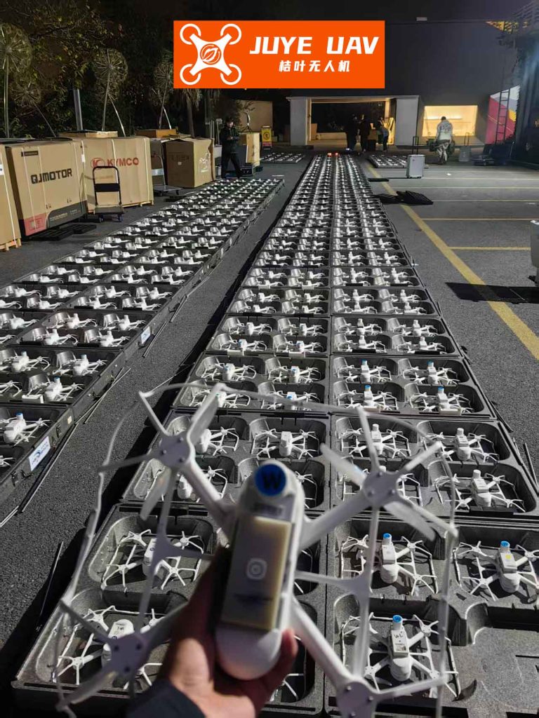
The coordination of multiple autonomous agents, particularly in the domain of aerial robotics, represents a frontier of significant academic and practical interest. Among these, the drone formation problem stands out due to its wide applicability in areas such as precision agriculture, infrastructure inspection, search and rescue, and aerial light shows, as visually suggested by the image. A well-coordinated drone formation offers substantial advantages over a single vehicle, including increased operational efficiency, enhanced spatial coverage, greater system redundancy, and improved task completion robustness. The core challenge lies in designing control algorithms that enable a group of drones to achieve and maintain a desired geometrical pattern—a formation—and to dynamically reconfigure this pattern in response to task demands or environmental constraints.
Traditional approaches to drone formation control often rely on fixed communication topologies, such as the leader-follower structure. While conceptually simple, these architectures introduce a critical point of failure: the loss of the leader can destabilize the entire formation. Furthermore, a fixed communication graph may become suboptimal or even unreliable during formation reconfiguration. As drones maneuver to new relative positions, communication links can be stretched beyond their reliable range, or environmental interference can degrade signal quality on specific paths. This necessitates an intelligent, adaptive framework for managing inter-agent communications.
In this article, I present a comprehensive methodology for the control of quadrotor drone formation reconfiguration based on an adaptive, switching communication topology integrated with a robust Integral Sliding Mode Control (ISMC) strategy. The primary objective is to ensure stable and precise tracking of a time-varying formation pattern while autonomously managing the communication network to preserve link reliability. The quadrotor, being an underactuated system with six degrees of freedom and only four control inputs (collective thrust and three moments), poses a unique control challenge. We address this by hierarchically designing controllers: a high-level formation controller for translational motion and low-level attitude stabilizers.
1. System Modeling and Problem Formulation
1.1 Quadrotor Dynamical Model
The quadrotor UAV is modeled as a rigid body. Let $\mathcal{I} = \{O’, x’, y’, z’\}$ denote the inertial frame and $\mathcal{B} = \{O, x, y, z\}$ the body-fixed frame attached to the vehicle’s center of mass, with the $z$-axis pointing upwards. The equations of motion are derived using the Newton-Euler formulation. The translational dynamics are governed by:
$$
\begin{aligned}
\dot{\mathbf{P}} &= \mathbf{V} \\
m\dot{\mathbf{V}} &= U_1 \mathbf{R} \mathbf{e}_3 – mg\mathbf{e}_3
\end{aligned}
$$
where $\mathbf{P} = [x, y, z]^T$ and $\mathbf{V} = [v_x, v_y, v_z]^T$ are the position and velocity vectors in $\mathcal{I}$, $m$ is the mass, $g$ is gravitational acceleration, $\mathbf{e}_3 = [0,0,1]^T$, and $U_1$ is the total thrust input. The matrix $\mathbf{R} \in SO(3)$ is the rotation matrix from $\mathcal{B}$ to $\mathcal{I}$, parameterized by the ZYX Euler angles $\boldsymbol{\Theta} = [\phi, \theta, \psi]^T$ (roll, pitch, yaw).
The rotational dynamics are given by:
$$
\begin{aligned}
\dot{\boldsymbol{\Theta}} &= \boldsymbol{\Omega} \\
\mathbf{J} \dot{\boldsymbol{\Omega}} &= \boldsymbol{\Gamma} – \mathbf{F}_c
\end{aligned}
$$
Here, $\boldsymbol{\Omega} = [p, q, r]^T$ is the angular velocity vector expressed in $\mathcal{B}$, $\boldsymbol{\Gamma} = [\tau_\phi, \tau_\theta, \tau_\psi]^T$ is the control torque input, $\mathbf{J}$ is the inertia tensor expressed in the inertial frame (a complex matrix dependent on $\boldsymbol{\Theta}$ and the principal moments of inertia $I_{xx}, I_{yy}, I_{zz}$), and $\mathbf{F}_c$ represents the Coriolis and centrifugal terms.
1.2 Formal Description of Drone Formation and Reconfiguration
Consider a drone formation consisting of $n$ identical quadrotors. The desired geometrical pattern for the formation is defined by a set of relative position vectors. Let $\mathbf{r}_i^d(t) \in \mathbb{R}^3$ denote the desired position of the $i$-th drone relative to a virtual reference point (e.g., the formation centroid). The desired relative displacement between drone $i$ and drone $j$ is thus $\mathbf{r}_{ij}^d(t) = \mathbf{r}_i^d(t) – \mathbf{r}_j^d(t)$.
The formation tracking error for the entire group can be defined in a consensus-like form. The control objective for formation reconfiguration is to ensure:
$$
\lim_{t \to \infty} \left( \mathbf{P}_i(t) – \mathbf{P}_j(t) \right) = \mathbf{r}_{ij}^d(t), \quad \forall i, j \in \{1, \dots, n\}
$$
where $\mathbf{P}_i(t)$ is the actual position of drone $i$. This implies that the drones must synchronize their motions to achieve the time-varying offsets $\mathbf{r}_{ij}^d(t)$. A more compact description is presented in the following table, summarizing the mathematical representation of different formation states.
| Formation State | Mathematical Description | Control Objective |
|---|---|---|
| Static Formation | $\mathbf{r}_{ij}^d$ is constant $\forall i,j$. | $\lim_{t \to \infty} (\mathbf{P}_i – \mathbf{P}_j) = \mathbf{r}_{ij}^d$ |
| Reconfiguring Formation | $\mathbf{r}_{ij}^d(t)$ is a time-varying vector. | $\lim_{t \to \infty} (\mathbf{P}_i – \mathbf{P}_j) = \mathbf{r}_{ij}^d(t)$ |
| Formation Tracking | $\mathbf{r}_{i}^d(t)$ includes a trajectory for the virtual reference. | $\lim_{t \to \infty} (\mathbf{P}_i – \mathbf{P}_j) = \mathbf{r}_{ij}^d(t)$ and $\lim_{t \to \infty} (\frac{1}{n}\sum \mathbf{P}_i) = \mathbf{P}_{ref}(t)$ |
1.3 Adaptive Switching Communication Topology
The information flow within the drone formation is modeled as a directed graph $\mathcal{G}^{(k)} = (\mathcal{V}, \mathcal{E}^{(k)}, \mathcal{A}^{(k)})$. Here, $\mathcal{V} = \{v_1, \dots, v_n\}$ is the set of nodes (drones), $\mathcal{E}^{(k)} \subseteq \mathcal{V} \times \mathcal{V}$ is the set of edges at switching index $k$, and $\mathcal{A}^{(k)} = [a_{ij}^{(k)}]$ is the weighted adjacency matrix. An edge $(v_j, v_i) \in \mathcal{E}^{(k)}$ exists if drone $i$ receives information from drone $j$, in which case $a_{ij}^{(k)} > 0$; otherwise, $a_{ij}^{(k)} = 0$. The Laplacian matrix is $\mathbf{L}^{(k)} = \mathbf{D}^{(k)} – \mathcal{A}^{(k)}$, where $\mathbf{D}^{(k)}$ is the in-degree diagonal matrix.
The core of the adaptive strategy is a communication cost function $W(v_i, v_j, t)$. This function quantitatively assesses the viability and quality of a communication link between two drones. For a practical drone formation, $W$ can depend on multiple factors:
$$
W(v_i, v_j, t) = f\left( \|\mathbf{P}_{ij}(t)\|, \ \text{SNR}_{ij}(t), \ \eta_{ij}(t), \ \ldots \right)
$$
where $\|\mathbf{P}_{ij}(t)\|$ is the Euclidean distance, $\text{SNR}_{ij}(t)$ is the signal-to-noise ratio, and $\eta_{ij}(t)$ represents environmental interference. A simple yet effective choice is to base it primarily on distance: $W(v_i, v_j, t) = \|\mathbf{P}_{ij}(t)\|$.
The switching logic is governed by two thresholds, $\Lambda_1$ and $\Lambda_2$, with $\Lambda_2 > \Lambda_1$ to introduce hysteresis and prevent chattering (rapid, undesirable switching).
- Link Establishment: If $W(v_i, v_j, t) \leq \Lambda_1$ and no link exists $(a_{ij}=0)$, then a new link is established $(a_{ij} \to \bar{a}_{ij}>0)$.
- Link Severance: If $W(v_i, v_j, t) \geq \Lambda_2$ and a link exists $(a_{ij}>0)$, then the existing link is severed $(a_{ij} \to 0)$.
This mechanism ensures the communication graph $\mathcal{G}^{(k)}$ switches to a new topology $\mathcal{G}^{(k+1)}$ whenever the relative configuration of the drone formation causes link costs to cross the defined thresholds. The goal is to maintain a topology that is both connected (or at least has a spanning tree) to allow consensus and reliable, with all active links operating below a quality ceiling.
| Communication Paradigm | Topology Structure | Advantages | Disadvantages |
|---|---|---|---|
| Fixed Topology (e.g., Leader-Follower) | Static, predetermined graph (e.g., spanning tree). | Simple design and analysis. | Single point of failure; poor adaptability to changing conditions. |
| Adaptive Switching Topology | Graph $\mathcal{G}^{(k)}$ switches based on real-time link quality $W$. | Robust to link failures; optimizes communication reliability; enables complex reconfiguration. | More complex stability analysis; requires mechanism to prevent chattering. |
2. Integral Sliding Mode Controller Design for Formation Reconfiguration
Sliding Mode Control (SMC) is renowned for its robustness against model uncertainties and bounded disturbances. The Integral Sliding Mode (ISMC) variant incorporates an integral term to eliminate steady-state error and ensure the sliding manifold is reached from the initial time, enhancing performance. This robustness is crucial for a drone formation operating under dynamic reconfiguration and variable communication conditions.
2.1 Formation-Level Translational Controller
The control goal for the $i$-th drone’s translation is to track a desired acceleration command $\mathbf{u}_{p,i}$ that will enforce formation cohesion. We define the velocity synchronization error for the entire drone formation based on the current communication topology $\mathcal{G}^{(k)}$:
$$
\mathbf{V}_e = \left[ \mathbf{L}^{(k)} \otimes \mathbf{I}_3 \right] \begin{bmatrix} \mathbf{V}_1 \\ \mathbf{V}_2 \\ \vdots \\ \mathbf{V}_n \end{bmatrix} – \begin{bmatrix} \sum_{j \in N_1} a_{1j} \dot{\mathbf{r}}_{1j}^d(t) \\ \sum_{j \in N_2} a_{2j} \dot{\mathbf{r}}_{2j}^d(t) \\ \vdots \\ \sum_{j \in N_n} a_{nj} \dot{\mathbf{r}}_{nj}^d(t) \end{bmatrix}
$$
where $\otimes$ is the Kronecker product, $\mathbf{I}_3$ is the 3×3 identity matrix, and $N_i$ is the neighbor set of drone $i$ under $\mathcal{G}^{(k)}$. The first term promotes velocity consensus, while the second term injects the desired relative velocity for reconfiguration.
The integral sliding surface $\mathbf{s}_p \in \mathbb{R}^{3n}$ is defined as:
$$
\mathbf{s}_p = \mathbf{V}_e + \boldsymbol{\Lambda}_p \int_0^t \mathbf{V}_e \, d\tau
$$
where $\boldsymbol{\Lambda}_p$ is a positive definite diagonal gain matrix. Taking the derivative and substituting the translational dynamics $\dot{\mathbf{V}}_i = (1/m)(U_{1,i}\mathbf{R}_i\mathbf{e}_3 – mg\mathbf{e}_3)$ yields:
$$
\dot{\mathbf{s}}_p = \left[ \mathbf{L}^{(k)} \otimes \mathbf{I}_3 \right] \begin{bmatrix} \frac{1}{m}(U_{1,1}\mathbf{R}_1\mathbf{e}_3) \\ \vdots \\ \frac{1}{m}(U_{1,n}\mathbf{R}_n\mathbf{e}_3) \end{bmatrix} – \mathbf{g}_0 – \dot{\mathbf{r}}_d + \boldsymbol{\Lambda}_p \mathbf{V}_e
$$
with $\mathbf{g}_0 = [g\mathbf{e}_3^T, \dots, g\mathbf{e}_3^T]^T$ and $\dot{\mathbf{r}}_d$ representing the stacked desired relative acceleration terms. To achieve $\dot{\mathbf{s}}_p = 0$, we solve for the equivalent virtual control $\mathbf{u}_{p}^{eq} = [ (U_{1,1}\mathbf{R}_1\mathbf{e}_3)^T, \dots ]^T$. This requires the pseudoinverse $(\cdot)^+$ due to the rank deficiency of $\mathbf{L}^{(k)}$:
$$
\mathbf{u}_{p}^{eq} = m \left( \left[ \mathbf{L}^{(k)} \otimes \mathbf{I}_3 \right]^+ \left( \mathbf{g}_0 + \dot{\mathbf{r}}_d – \boldsymbol{\Lambda}_p \mathbf{V}_e \right) \right)
$$
The final robust ISMC law adds a switching term to reject perturbations and handle the mismatch between $\mathbf{u}_{p}^{eq}$ and the actual achievable control:
$$
\mathbf{u}_{p} = \mathbf{u}_{p}^{eq} – \mathbf{K}_p \cdot \text{sat}\left(\frac{\mathbf{s}_p}{\Phi_p}\right)
$$
where $\mathbf{K}_p$ is a diagonal gain matrix with sufficiently large positive entries, and $\text{sat}(\cdot)$ is a saturation function with boundary layer $\Phi_p$ used to mitigate chattering. This $\mathbf{u}_{p}$ is a virtual acceleration command for the entire drone formation.
2.2 Individual Drone Attitude and Thrust Control
For each drone $i$, the virtual command $\mathbf{u}_{p,i}$ must be decomposed into a scalar thrust $U_{1,i}$ and a desired attitude $\mathbf{R}_{d,i}$ (or equivalently, desired Euler angles $\boldsymbol{\Theta}_{d,i}$). From $\mathbf{u}_{p,i} = U_{1,i} \mathbf{R}_{d,i} \mathbf{e}_3$, we can solve:
$$
\begin{aligned}
U_{1,i} &= \|\mathbf{u}_{p,i}\| \\
\phi_{d,i} &= \arctan\left( \frac{u_{p,i,y} \cos\psi_{d,i} – u_{p,i,x} \sin\psi_{d,i}}{u_{p,i,z}} \right) \\
\theta_{d,i} &= \arctan\left( \frac{u_{p,i,x} \cos\psi_{d,i} + u_{p,i,y} \sin\psi_{d,i}}{u_{p,i,z}} \right)
\end{aligned}
$$
The yaw angle $\psi_{d,i}$ can be separately specified, often set to zero or a common value for the formation. Next, an inner-loop ISMC attitude controller is designed to track $\boldsymbol{\Theta}_{d,i}$. Define the attitude error $\boldsymbol{\Omega}_{e,i} = \boldsymbol{\Omega}_i – \dot{\boldsymbol{\Theta}}_{d,i}$ and the sliding surface:
$$
\mathbf{s}_{a,i} = \boldsymbol{\Omega}_{e,i} + \boldsymbol{\Lambda}_a \int_0^t \boldsymbol{\Omega}_{e,i} \, d\tau
$$
The attitude control torque $\boldsymbol{\Gamma}_i$ is derived similarly:
$$
\boldsymbol{\Gamma}_i = \boldsymbol{\Gamma}_i^{eq} – \mathbf{K}_{a,i} \cdot \text{sat}\left(\frac{\mathbf{s}_{a,i}}{\Phi_a}\right)
$$
where $\boldsymbol{\Gamma}_i^{eq} = \mathbf{J}_i (-\boldsymbol{\Lambda}_a \boldsymbol{\Omega}_{e,i} + \ddot{\boldsymbol{\Theta}}_{d,i}) + \mathbf{F}_{c,i}$ is the equivalent torque based on the nominal rotational dynamics, and $\mathbf{K}_{a,i}$ is a robust diagonal gain matrix.
3. Stability Analysis of the Switched Formation System
The closed-loop system is a switched nonlinear system due to the changing topology $\mathcal{G}^{(k)}$. Stability is analyzed using a Common Lyapunov Function (CLF) approach, which provides stability guarantees under arbitrary switching if a single Lyapunov function can be found that decreases along trajectories for all possible subsystems (topologies).
Consider the combined Lyapunov candidate for the entire drone formation:
$$
V = V_p + V_a = \frac{1}{2} \mathbf{s}_p^T \mathbf{s}_p + \frac{1}{2} \sum_{i=1}^n \mathbf{s}_{a,i}^T \mathbf{s}_{a,i}
$$
Taking the derivative of $V_p$ along the trajectories and substituting the controller $\mathbf{u}_p$ yields:
$$
\dot{V}_p = \mathbf{s}_p^T \dot{\mathbf{s}}_p = \mathbf{s}_p^T \left( \left[ \mathbf{L}^{(k)} \otimes \mathbf{I}_3 \right] \frac{1}{m} \left( \mathbf{u}_p – \mathbf{u}_p^{eq} \right) \right)
$$
Substituting $\mathbf{u}_p = \mathbf{u}_p^{eq} – \mathbf{K}_p \text{sat}(\mathbf{s}_p/\Phi_p)$ gives:
$$
\dot{V}_p = -\frac{1}{m} \mathbf{s}_p^T \left( \left[ \mathbf{L}^{(k)} \otimes \mathbf{I}_3 \right] \mathbf{K}_p \text{sat}\left(\frac{\mathbf{s}_p}{\Phi_p}\right) \right)
$$
Since $\mathbf{L}^{(k)}$ for any balanced, strongly connected directed graph is positive semi-definite with a simple zero eigenvalue, and the vector $\mathbf{K}_p \text{sat}(\mathbf{s}_p/\Phi_p)$ lies in the column space of $\left[ \mathbf{L}^{(k)} \otimes \mathbf{I}_3 \right]$ (it is composed of inter-drone differences), the quadratic form is non-positive. In fact, it is negative definite with respect to $\mathbf{s}_p$ in the subspace orthogonal to the consensus manifold. Similarly, for each drone’s attitude:
$$
\dot{V}_a = \sum_{i=1}^n \mathbf{s}_{a,i}^T \left( -\mathbf{J}_i^{-1} \mathbf{K}_{a,i} \text{sat}\left(\frac{\mathbf{s}_{a,i}}{\Phi_a}\right) \right) < 0 \quad \text{for } \mathbf{s}_{a,i} \neq 0
$$
Thus, $\dot{V} = \dot{V}_p + \dot{V}_a < 0$ for all non-zero sliding vectors $\mathbf{s}_p$ and $\mathbf{s}_{a,i}$, and this holds for any topology $\mathcal{G}^{(k)}$ in the admissible set (balanced and strongly connected). $V$ serves as a Common Lyapunov Function, proving that the origin $(\mathbf{s}_p, \mathbf{s}_{a,i}) = 0$ is globally asymptotically stable under arbitrary switching among these topologies. Convergence of the sliding surfaces to zero implies convergence of the tracking errors $\mathbf{V}_e$ and $\boldsymbol{\Omega}_{e,i}$ to zero, which in turn ensures the drone formation achieves its reconfiguration objective $\mathbf{P}_i – \mathbf{P}_j \to \mathbf{r}_{ij}^d(t)$.
4. Simulation Results and Performance Evaluation
To validate the proposed adaptive topology ISMC framework for drone formation reconfiguration, a numerical simulation was conducted with a fleet of five quadrotor UAVs. The key simulation parameters are summarized below.
| Parameter Category | Symbol | Value |
|---|---|---|
| Quadrotor Dynamics | $m$ | 3.0 kg |
| $(I_{xx}, I_{yy}, I_{zz})$ | $(0.004, 0.004, 0.008)$ kg·m² | |
| Initial Positions/Velocities | See detailed initial conditions table. | |
| Formation Pattern | $t \in [0, 9]$ s | Linear vertical column: $\mathbf{r}_{i,i+1}^d = [0, 0, 2]^T$ m |
| $t > 9$ s | “V” shape in 3D with specific offsets. | |
| Controller Gains | $\boldsymbol{\Lambda}_p$, $\mathbf{K}_p$ | $\text{diag}(0.5, 0.5, 0.5)$, $\text{diag}(15, 15, 15)$ |
| $\boldsymbol{\Lambda}_a$, $\mathbf{K}_{a,i}$ | $\text{diag}(2, 2, 2)$, $\text{diag}(0.8, 0.8, 1.5)$ | |
| $\Phi_p$, $\Phi_a$ | 0.1, 0.05 | |
| Communication Topology | Cost Function $W$ | Euclidean distance $\|\mathbf{P}_{ij}(t)\|$ |
| Thresholds $(\Lambda_1, \Lambda_2)$ | (3.5 m, 5.5 m) |
| Drone Index | Initial Position [m] | Initial Velocity [m/s] |
|---|---|---|
| 1 | $[3, 1, 50]^T$ | $[-0.1, 0, 1]^T$ |
| 2 | $[-1, 3, 50]^T$ | $[-0.3, -0.1, 1]^T$ |
| 3 | $[2, -1, 50]^T$ | $[-0.1, -0.1, 1]^T$ |
| 4 | $[1, 1, 50]^T$ | $[-0.1, 0, 1]^T$ |
| 5 | $[0, 0, 52]^T$ | $[0, -0.1, 0]^T$ |
The simulation demonstrates the complete reconfiguration sequence. Initially, the drones stabilize into a vertical column formation. At $t = 9$ s, the desired formation switches to a 3D “V” shape. The adaptive communication logic triggers topology switches as distances change during this maneuver. For instance, when two drones move far apart, the costly link is dropped, and new, shorter links are established with nearer neighbors, maintaining a connected graph. The ISMC controllers drive the translational and attitude sliding surfaces to zero rapidly despite the switching topology and nonlinear dynamics.
The formation tracking error, defined as $E_{form}(t) = \frac{1}{n} \sum_{i=1}^n \|\mathbf{P}_i(t) – \mathbf{P}_j(t) – \mathbf{r}_{ij}^d(t)\|$ for a representative pair, converges to a small neighborhood of zero after a brief transient during the reconfiguration command. The control inputs $U_{1,i}$ and $\boldsymbol{\Gamma}_i$ remain within feasible actuator limits and exhibit smooth behavior due to the boundary layer saturation function, with only minor high-frequency activity visible during topology switches, effectively demonstrating the controller’s robustness.
5. Conclusion
This article has presented a robust and adaptive framework for controlling the reconfiguration of a quadrotor drone formation. The integration of an adaptive, switching communication topology with Integral Sliding Mode Control addresses two critical challenges simultaneously: maintaining reliable inter-agent communication under changing spatial configurations and providing robust tracking performance against model uncertainties and disturbances inherent in multi-agent aerial systems. The stability of the overall switched nonlinear system was formally proven using a Common Lyapunov Function approach. Simulation studies validated the efficacy of the method, showing smooth and accurate reconfiguration of a five-drone formation while the communication network self-optimized based on link distance.
The proposed architecture moves beyond fragile leader-follower schemes and static communication graphs, offering a more resilient and intelligent paradigm for cooperative aerial robotics. Future work will focus on extending the communication cost function $W$ to incorporate more realistic factors like packet loss and bandwidth constraints, experimentally validating the framework with physical drone swarms, and investigating distributed optimization techniques to select the optimal topology from the set of feasible connected graphs, further enhancing the efficiency and robustness of autonomous drone formation operations.